Page 1005 of 1659
Checking Exhaust System
Check exhaust pipes, muffler and mounting for improper
attachment, leaks, cracks, damage, loose connections, chafing
or deterioration.
Checking Clutch Fluid Level and Leaks
If fluid level is extremely low, check clutch system for leaks.
Checking Clutch System
Check fluid lines and operating cylinder for improper
connections, cracks, damage, chafing or deterioration.
Checking M/T Oil
Check for oil leakage and oil level.
Never start engine while checking oil level.
Filler plug:
: 25 - 34 N´m (2.5 - 3.5 kg-m, 18 - 25 ft-lb)
Changing M/T Oil
1. Drain oil from drain plug and refill with new gear oil.
2. Check oil level.
Oil grade and viscosity:
API GL-4. Refer to ``RECOMMENDED FLUIDS AND
LUBRICANTS'', MA-12.
Oil capacity:
FS5W71C
2WD 2.0ø(3-1/2 Imp pt)
4WD 4.9ø(8-5/8 Imp pt)
FS5R30A
4WD 5.1ø(9 Imp pt)
Drain plug:
: 25 - 34 N´m (2.5 - 3.5 kg-m, 18 - 25 ft-lb)
SMA211A
SMA928C
SMA741A
SMA103
CHASSIS AND BODY MAINTENANCE
MA-32
Page 1006 of 1659

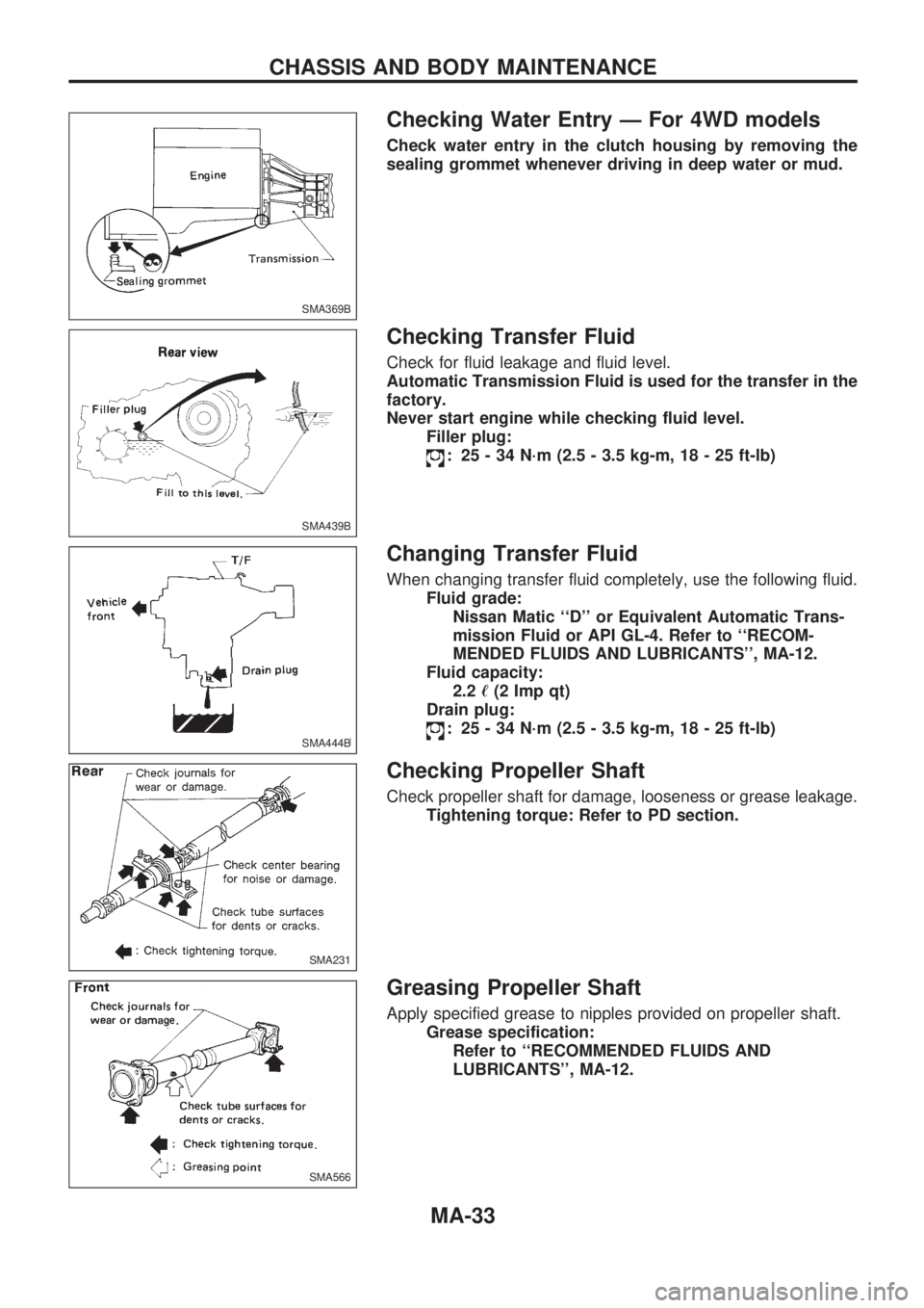
Checking Water Entry Ð For 4WD models
Check water entry in the clutch housing by removing the
sealing grommet whenever driving in deep water or mud.
Checking Transfer Fluid
Check for fluid leakage and fluid level.
Automatic Transmission Fluid is used for the transfer in the
factory.
Never start engine while checking fluid level.
Filler plug:
: 25 - 34 N´m (2.5 - 3.5 kg-m, 18 - 25 ft-lb)
Changing Transfer Fluid
When changing transfer fluid completely, use the following fluid.
Fluid grade:
Nissan Matic ``D'' or Equivalent Automatic Trans-
mission Fluid or API GL-4. Refer to ``RECOM-
MENDED FLUIDS AND LUBRICANTS'', MA-12.
Fluid capacity:
2.2ø(2 Imp qt)
Drain plug:
: 25 - 34 N´m (2.5 - 3.5 kg-m, 18 - 25 ft-lb)
Checking Propeller Shaft
Check propeller shaft for damage, looseness or grease leakage.
Tightening torque: Refer to PD section.
Greasing Propeller Shaft
Apply specified grease to nipples provided on propeller shaft.
Grease specification:
Refer to ``RECOMMENDED FLUIDS AND
LUBRICANTS'', MA-12.
SMA369B
SMA439B
SMA444B
SMA231
SMA566
CHASSIS AND BODY MAINTENANCE
MA-33
Page 1010 of 1659

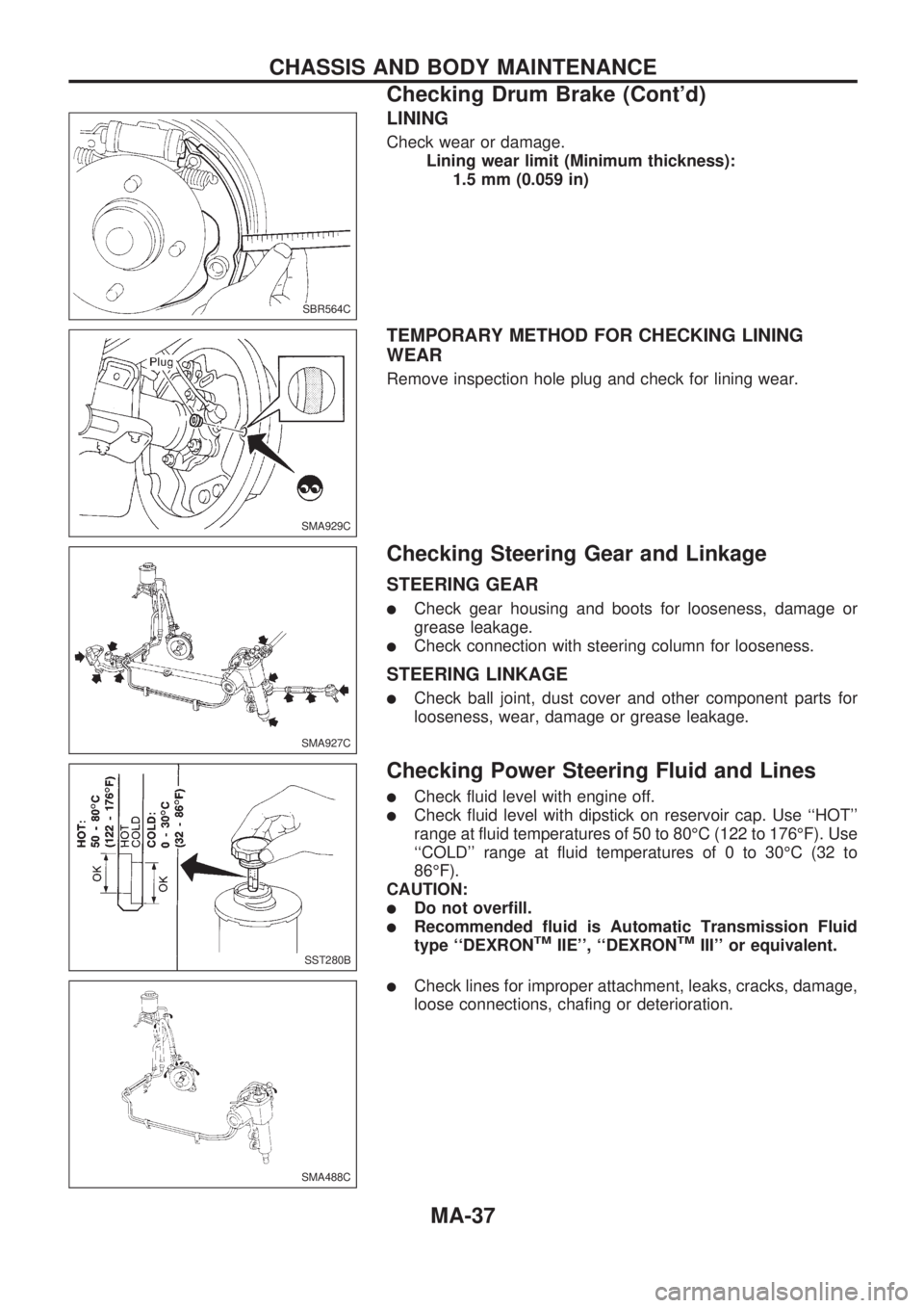
LINING
Check wear or damage.
Lining wear limit (Minimum thickness):
1.5 mm (0.059 in)
TEMPORARY METHOD FOR CHECKING LINING
WEAR
Remove inspection hole plug and check for lining wear.
Checking Steering Gear and Linkage
STEERING GEAR
lCheck gear housing and boots for looseness, damage or
grease leakage.
lCheck connection with steering column for looseness.
STEERING LINKAGE
lCheck ball joint, dust cover and other component parts for
looseness, wear, damage or grease leakage.
Checking Power Steering Fluid and Lines
lCheck fluid level with engine off.
lCheck fluid level with dipstick on reservoir cap. Use ``HOT''
range at fluid temperatures of 50 to 80ÉC (122 to 176ÉF). Use
``COLD'' range at fluid temperatures of 0 to 30ÉC (32 to
86ÉF).
CAUTION:
lDo not overfill.
lRecommended fluid is Automatic Transmission Fluid
type ``DEXRONTMIIE'', ``DEXRONTMIII'' or equivalent.
lCheck lines for improper attachment, leaks, cracks, damage,
loose connections, chafing or deterioration.
SBR564C
SMA929C
SMA927C
SST280B
SMA488C
CHASSIS AND BODY MAINTENANCE
Checking Drum Brake (Cont'd)
MA-37
Page 1014 of 1659
Checking Body Corrosion
Visually check the body sheet metal panel for corrosion, paint damage (scratches, chipping, rubbing, etc.)
or damage to the anti-corrosion materials. In particular, check the following locations.
Hemmed portion
Hood front end, door lower end, trunk lid rear end, etc.
Panel joint
Side sill of rear fender and center pillar, rear wheel housing of rear fender, around strut tower in engine
compartment, etc.
Panel edge
Trunk lid opening, sunroof opening, fender wheelarch flange, fuel filler lid flange, around holes in panel, etc.
Parts contact
Waist molding, windshield molding, bumper, etc.
Protectors
Damage or condition of mudguard, fender protector, chipping protector, etc.
Anti-corrosion materials
Damage or separation of anti-corrosion materials under the body.
Drain holes
Condition of drain holes at door and side sill.
When repairing corroded areas, refer to the Corrosion Repair Manual.
CHASSIS AND BODY MAINTENANCE
MA-41
Page 1026 of 1659
Replacing Rear Oil Seal Ð 2WD Model
REMOVAL
1. Remove the propeller shaft. Refer to PD section (``Removal
and Installation'', ``PROPELLER SHAFT'').
2. Remove rear oil seal using Tool.
lAlways replace with a new seal once it has been
removed.
INSTALLATION
1. Install new oil seal until it stops.
lApply multi-purpose grease to seal lip of oil seal before
installing.
2. Install any part removed.
Position Switch Check
lCheck continuity.
Switch Gear position Continuity
Back-up lamp switchReverse Yes
Except reverse No
Neutral position switch
(KA24E engine model
only)Neutral Yes
Except neutral No
SMT476AA
SMT477AA
SMT451BD
ON-VEHICLE SERVICEFS5W71C
MT-9
Page 1120 of 1659
CAUTION:
Do not run engine when only one wheel (rear) is off the
ground.
Preparation for Disassembly
CHECKING DIFFERENTIAL TORQUE
Measure differential torque with Tools.
If it is not within the specifications, inspect components of limited
slip differential.
Differential torque:
88 - 108 N´m
(9.0 - 11.0 kg-m, 65 - 80 ft-lb)
Tool numbers:
VAKV38105110
VBKV38105120
Disassembly
1. Remove couple bolts using a press.
Tool number: ST33081000
2. Separate differential cases A and B.
Draw out component parts (discs and plates, etc.).
Put marks on differential cases so that they can be rein-
stalled in their original positions.
SPD419A
SPD415
SPD420A
LIMITED SLIP DIFFERENTIALC200
PD-39
Page 1142 of 1659
CAUTION:
Do not run engine when only one wheel (rear) is off the
ground.
Preparation for Disassembly
CHECKING DIFFERENTIAL TORQUE
Measure differential torque with Tools.
If it is not within the specifications, inspect components of limited
slip differential.
Differential torque:
201 - 240 N´m
(20.5 - 24.5 kg-m, 148 - 177 ft-lb)
Tool numbers:
VAKV38105210
VBKV38105220
Disassembly
1. Remove side bearing inner cone with Tool.
2. Loosen ring gear bolts in a criss-cross fashion.
3. Tap ring gear off gear case with a soft hammer.
Tap evenly all around to keep ring gear from binding.
SPD423A
SPD415
SPD424A
LIMITED SLIP DIFFERENTIALH233B
PD-61
Page 1207 of 1659
Precautions
lWhen installing rubber parts, final tightening must be
carried out under unladen condition* with tires on
ground.
*: Fuel, radiator coolant and engine oil full. Spare tire,
jack, hand tools and mats in designated positions.
lUse flare nut wrench when removing or installing brake
tubes.
lAfter installing removed suspension parts, check wheel
alignment and adjust if necessary.
lAlways torque brake lines when installing.
Special Service Tools
Tool number
Tool nameDescription
KV40101000
Axle stand
NT159
Removing rear axle shaft
ST36230000
Sliding hammer
NT126
Removing rear axle shaft
ST38020000
Bearing lock nut wrench
NT160
Removing wheel bearing lock nut
KV40106500
Rear axle shaft bearing
puller
NT683
Removing wheel bearing and ABS sensor rotor
ST37840000
Rear axle shaft guide
NT162
Installing rear axle shaft
GG94310000
Flare nut torque
wrench
NT406
Removing and installing brake piping
a: 10 mm (0.39 in)
SBR820BA
PRECAUTIONS AND PREPARATION
RA-1