Page 1617 of 1659

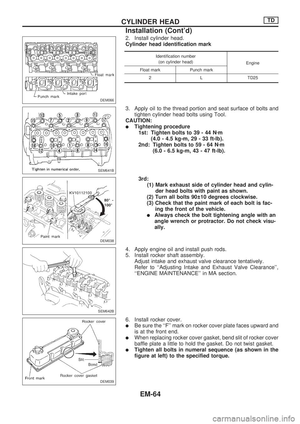
2. Install cylinder head.
Cylinder head identification mark
Identification number
(on cylinder head)
Engine
Float mark Punch mark
2 L TD25
3. Apply oil to the thread portion and seat surface of bolts and
tighten cylinder head bolts using Tool.
CAUTION:
lTightening procedure
1st: Tighten bolts to 39 - 44 Nzm
(4.0 - 4.5 kg-m, 29 - 33 ft-lb).
2nd: Tighten bolts to 59 - 64 Nzm
(6.0 - 6.5 kg-m, 43 - 47 ft-lb).
3rd:
(1) Mark exhaust side of cylinder head and cylin-
der head bolts with paint as shown.
(2) Turn all bolts 90 10 degrees clockwise.
(3) Check that the paint mark of each bolt is fac-
ing the front of the vehicle.
lAlways check the bolt tightening angle with an
angle wrench or protractor. Do not check visu-
ally.
4. Apply engine oil and install push rods.
5. Install rocker shaft assembly.
Adjust intake and exhaust valve clearance tentatively.
Refer to ``Adjusting Intake and Exhaust Valve Clearance'',
``ENGINE MAINTENANCE'' in MA section.
6. Install rocker cover.
lBe sure the ``F'' mark on rocker cover plate faces upward and
is at the front end.
lWhen replacing rocker cover gasket, bend slit of rocker cover
baffle plate a little to hold the gasket. Do not twist gasket.
lTighten all bolts in numeral sequence (as shown in the
figure at left) to the specified torque.
DEM066
SEM641B
DEM038
SEM642B
DEM039
CYLINDER HEADTD
Installation (Cont'd)
EM-64
Page 1628 of 1659
2. Check for scratches or seizure. If seizure is found, replace
cylinder liner.
3. Check amount of projection of cylinder liner.
Cylinder liner projection:
Standard
0.02 - 0.09 mm (0.0008 - 0.0035 in)
Deviation of each cylinder:
Less than 0.05 mm (0.0020 in)
CYLINDER LINER
Replacement
1. Remove cylinder liner with Tool.
2. Install cylinder liner with Tool.
3. Check amount of projection of cylinder liner.
PISTON TO CYLINDER WALL CLEARANCE
1. Measure piston and cylinder bore diameter.
Piston diameter ``A'':
Refer to SDS, EM-103.
Measuring point ``a''
(Distance from the top): mm (in)
70 (2.76)
2. Check that piston clearance is within the specification.
Piston clearance:
0.05 - 0.07 mm (0.0020 - 0.0028 in)
SEM920A
SEM849
SEM659B
SEM660B
ENGINE OVERHAULTD
Inspection and Replacement (Cont'd)
EM-75
Page 1629 of 1659

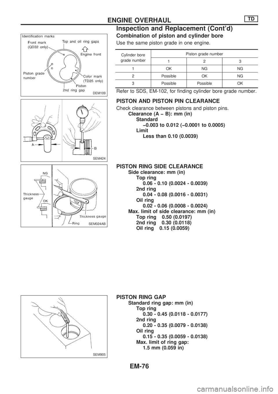
Combination of piston and cylinder bore
Use the same piston grade in one engine.
Cylinder bore
grade numberPiston grade number
123
1OKNGNG
2 Possible OK NG
3 Possible Possible OK
Refer to SDS, EM-102, for finding cylinder bore grade number.
PISTON AND PISTON PIN CLEARANCE
Check clearance between pistons and piston pins.
Clearance (A þ B): mm (in)
Standard
þ0.003 to 0.012 (þ0.0001 to 0.0005)
Limit
Less than 0.10 (0.0039)
PISTON RING SIDE CLEARANCE
Side clearance: mm (in)
Top ring
0.06 - 0.10 (0.0024 - 0.0039)
2nd ring
0.04 - 0.08 (0.0016 - 0.0031)
Oil ring
0.02 - 0.06 (0.0008 - 0.0024)
Max. limit of side clearance: mm (in)
Top ring 0.50 (0.0197)
2nd ring 0.30 (0.0118)
Oil ring 0.15 (0.0059)
PISTON RING GAP
Standard ring gap: mm (in)
Top ring
0.30 - 0.45 (0.0118 - 0.0177)
2nd ring
0.20 - 0.35 (0.0079 - 0.0138)
Oil ring
0.15 - 0.35 (0.0059 - 0.0138)
Max. limit of ring gap:
1.5 mm (0.059 in)
DEM109
SEM424
SEM024AB
SEM905
ENGINE OVERHAULTD
Inspection and Replacement (Cont'd)
EM-76
Page 1632 of 1659

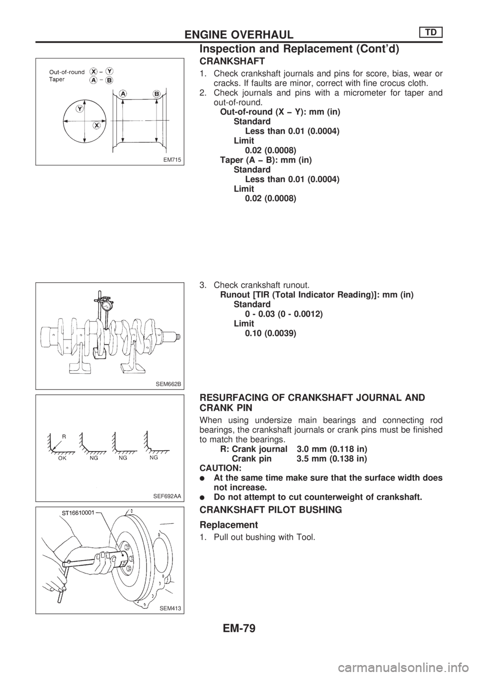
CRANKSHAFT
1. Check crankshaft journals and pins for score, bias, wear or
cracks. If faults are minor, correct with fine crocus cloth.
2. Check journals and pins with a micrometer for taper and
out-of-round.
Out-of-round (X þ Y): mm (in)
Standard
Less than 0.01 (0.0004)
Limit
0.02 (0.0008)
Taper (A þ B): mm (in)
Standard
Less than 0.01 (0.0004)
Limit
0.02 (0.0008)
3. Check crankshaft runout.
Runout [TIR (Total Indicator Reading)]: mm (in)
Standard
0 - 0.03 (0 - 0.0012)
Limit
0.10 (0.0039)
RESURFACING OF CRANKSHAFT JOURNAL AND
CRANK PIN
When using undersize main bearings and connecting rod
bearings, the crankshaft journals or crank pins must be finished
to match the bearings.
R: Crank journal 3.0 mm (0.118 in)
Crank pin 3.5 mm (0.138 in)
CAUTION:
lAt the same time make sure that the surface width does
not increase.
lDo not attempt to cut counterweight of crankshaft.
CRANKSHAFT PILOT BUSHING
Replacement
1. Pull out bushing with Tool.
EM715
SEM662B
SEF692AA
SEM413
ENGINE OVERHAULTD
Inspection and Replacement (Cont'd)
EM-79
Page 1633 of 1659
2. Insert pilot bushing until distance between flange end and
bushing is specified value.
Distance:
Approx. 5.6 - 6.0 mm (0.220 - 0.236 in)
FLYWHEEL RUNOUT
Runout (Total indicator reading):
Less than 0.15 mm (0.0059 in)
FRONT PLATE
Check front plate for warpage. If not within the limit, make flat or
replace front plate.
Warpage limit:
0.2 mm (0.008 in)
GEAR TRAIN
Camshaft drive gear, injection pump drive gear, oil
pump gear, idler gear and crankshaft gear
1. If gear tooth and key have scratches or are excessively worn,
replace gear and key.
2. Check gear train backlash before disassembling and after
assembling.
Method A (Using dial gauge)
Method B (Using fuse wire)
If beyond the limit, replace gear.
Backlash: mm (in)
Standard
0.07 - 0.11 (0.0028 - 0.0043)
Limit
0.20 (0.0079)
SEM089-A
SEM059A
SEM668B
DEM051
MEM151A
ENGINE OVERHAULTD
Inspection and Replacement (Cont'd)
EM-80
Page 1636 of 1659
lDrive replacer bar until the alignment mark on replacer bar
is aligned with the end of replacer guide.
Remove replacer set.
After installation, check that oil holes in camshaft bushings
are aligned with oil holes in cylinder block.
SEM601C
ENGINE OVERHAULTD
Inspection and Replacement (Cont'd)
EM-83
Page 1638 of 1659
lPress the bushing until its front end is 0.5 mm (0.020 in) from
the front surface of the cylinder block.
3. Check camshaft bushing clearance.
Refer to SDS, EM-101.
4. Install new welch plug into rear camshaft bushing hole with
a drift.
Apply liquid sealer.
CAMSHAFT ALIGNMENT
1. Check camshaft journal and cam surface for bend, wear or
damage.
If fault is beyond limit, replace.
2. Check camshaft bend at center journal.
If bend is greater than specified limit, repair or replace cam-
shaft.
Camshaft bend
(Total indicator reading): mm (in)
Standard
Less than 0.02 (0.0008)
Limit
Less than 0.06 (0.0024)
DEM053
SEM987B
SEM034
SEM670B
ENGINE OVERHAULTD
Inspection and Replacement (Cont'd)
EM-85