1998 NISSAN PICK-UP check engine
[x] Cancel search: check enginePage 1316 of 1659
CAUTION:
If it becomes necessary to start the engine with a booster
battery and jumper cables,
a. Use a 12-volt booster battery.
b. After connecting battery cables, ensure that they are
tightly clamped to battery terminals for good contact.
c. Never add distilled water through the hole used to check
specific gravity.
How to Handle Battery
METHODS OF PREVENTING OVER-DISCHARGE
The following precautions must be taken to prevent over-dis-
charging a battery.
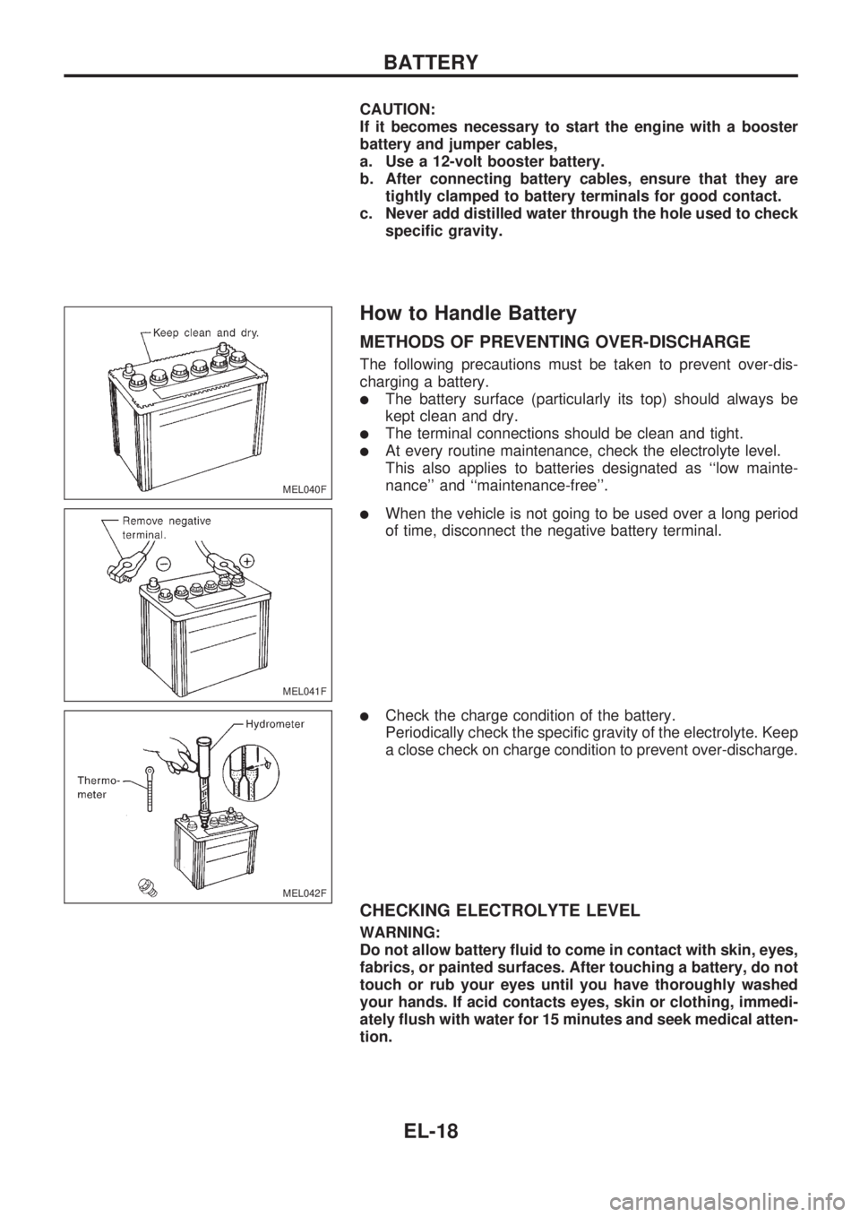
lThe battery surface (particularly its top) should always be
kept clean and dry.
lThe terminal connections should be clean and tight.
lAt every routine maintenance, check the electrolyte level.
This also applies to batteries designated as ``low mainte-
nance'' and ``maintenance-free''.
lWhen the vehicle is not going to be used over a long period
of time, disconnect the negative battery terminal.
lCheck the charge condition of the battery.
Periodically check the specific gravity of the electrolyte. Keep
a close check on charge condition to prevent over-discharge.
CHECKING ELECTROLYTE LEVEL
WARNING:
Do not allow battery fluid to come in contact with skin, eyes,
fabrics, or painted surfaces. After touching a battery, do not
touch or rub your eyes until you have thoroughly washed
your hands. If acid contacts eyes, skin or clothing, immedi-
ately flush with water for 15 minutes and seek medical atten-
tion.
MEL040F
MEL041F
MEL042F
BATTERY
EL-18
Page 1325 of 1659
Trouble Diagnoses
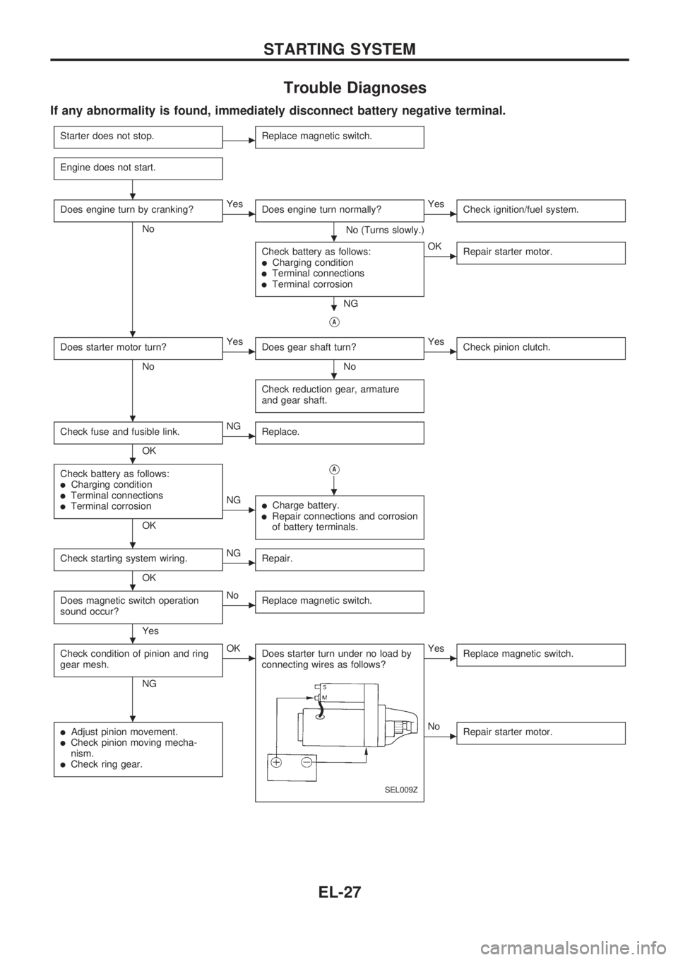
If any abnormality is found, immediately disconnect battery negative terminal.
Starter does not stop.cReplace magnetic switch.
Engine does not start.
Does engine turn by cranking?
No
cYes
Does engine turn normally?
No (Turns slowly.)
cYes
Check ignition/fuel system.
Check battery as follows:lCharging conditionlTerminal connectionslTerminal corrosion
NG
cOK
Repair starter motor.
VA
Does starter motor turn?
No
cYes
Does gear shaft turn?
No
cYes
Check pinion clutch.
Check reduction gear, armature
and gear shaft.
Check fuse and fusible link.
OK
cNG
Replace.
Check battery as follows:lCharging conditionlTerminal connectionslTerminal corrosion
OK
VA
cNGlCharge battery.lRepair connections and corrosion
of battery terminals.
Check starting system wiring.
OK
cNG
Repair.
Does magnetic switch operation
sound occur?
Yes
cNo
Replace magnetic switch.
Check condition of pinion and ring
gear mesh.
NG
cOK
Does starter turn under no load by
connecting wires as follows?
SEL009Z
cYes
Replace magnetic switch.
lAdjust pinion movement.lCheck pinion moving mecha-
nism.
lCheck ring gear.
cNo
Repair starter motor.
.
.
.
.
.
.
.
.
.
.
.
.
STARTING SYSTEM
EL-27
Page 1334 of 1659

Trouble Diagnoses
Before conducting an alternator test, make sure that the battery is fully charged. A 30-volt voltmeter and
suitable test probes are necessary for the test. The alternator can be checked easily by referring to the
Inspection Table.
lBefore starting, inspect the fusible link.
lUse fully charged battery.
GASOLINE ENGINE MODELS
Check the fol-
lowing:
lWarning
lamp bulb
lFuse for
warning lamp
Ignition switch
``ON''Warning lamp
``OFF''Disconnect connector (S, L) and
ground L harness side.Warning lamp
``OFF''
Warning lamp
``ON''Damaged IC
regulator.
Replace.
Warning lamp
``ON''
Engine start.
Engine speed:
1,500 rpmWarning lamp
``ON''Check the following:lDrive beltlFuse for S terminallConnector (S, L terminal) con-
nection
Engine idlingWarning lamp
``OFF''OK
Warning lamp
``ON''
Warning lamp
``OFF''OKEngine speed:
1,500 rpm
(Measure B
terminal volt-
age)More than
15.5VDamaged IC
regulator.
Replace.
No generationField circuit is
open.
Warning lamp: ``CHARGE'' warning lamp in combination meter
Note:
lIf the inspection result is OK even though the charging system is malfunctioning, check the B
terminal connection. (Check the tightening torque.)
lWhen field circuit is open, check condition of rotor coil, rotor slip ring and brush. If necessary,
replace faulty parts with new ones.
Malfunction indicator
The IC regulator warning function activates to illuminate ``CHARGE'' warning lamp, if any of the following
symptoms occur while alternator is operating:
lField circuit is open.
lExcessive voltage is produced.
CHARGING SYSTEM
EL-36
Page 1335 of 1659
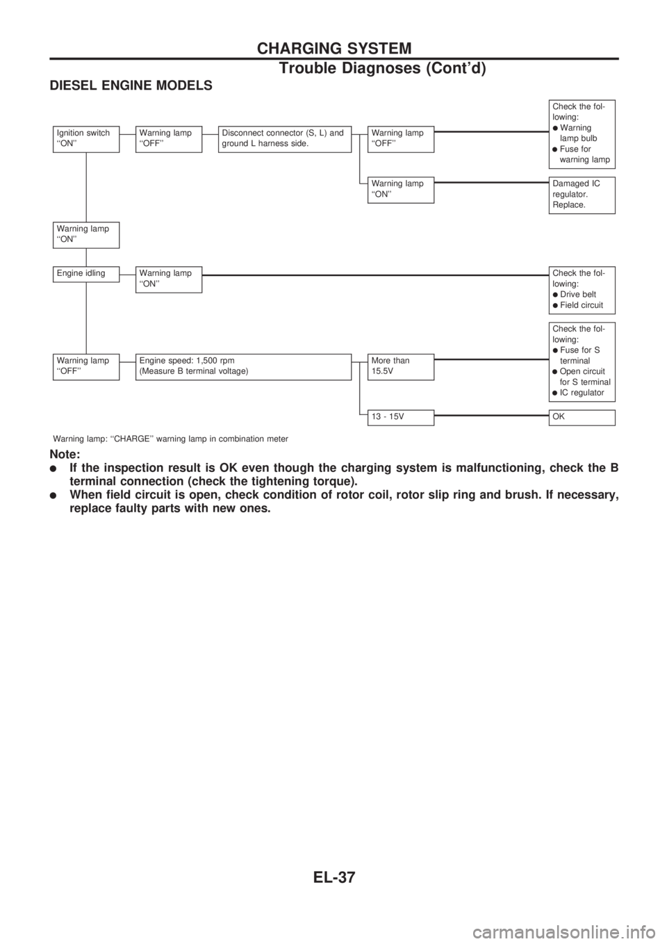
DIESEL ENGINE MODELS
Check the fol-
lowing:
lWarning
lamp bulb
lFuse for
warning lamp
Ignition switch
``ON''Warning lamp
``OFF''Disconnect connector (S, L) and
ground L harness side.Warning lamp
``OFF''
Warning lamp
``ON''Damaged IC
regulator.
Replace.
Warning lamp
``ON''
Engine idlingWarning lamp
``ON''Check the fol-
lowing:
lDrive beltlField circuit
Check the fol-
lowing:
lFuse for S
terminal
lOpen circuit
for S terminal
lIC regulator
Warning lamp
``OFF''Engine speed: 1,500 rpm
(Measure B terminal voltage)More than
15.5V
13 - 15VOK
Warning lamp: ``CHARGE'' warning lamp in combination meter
Note:
lIf the inspection result is OK even though the charging system is malfunctioning, check the B
terminal connection (check the tightening torque).
lWhen field circuit is open, check condition of rotor coil, rotor slip ring and brush. If necessary,
replace faulty parts with new ones.
CHARGING SYSTEM
Trouble Diagnoses (Cont'd)
EL-37
Page 1397 of 1659
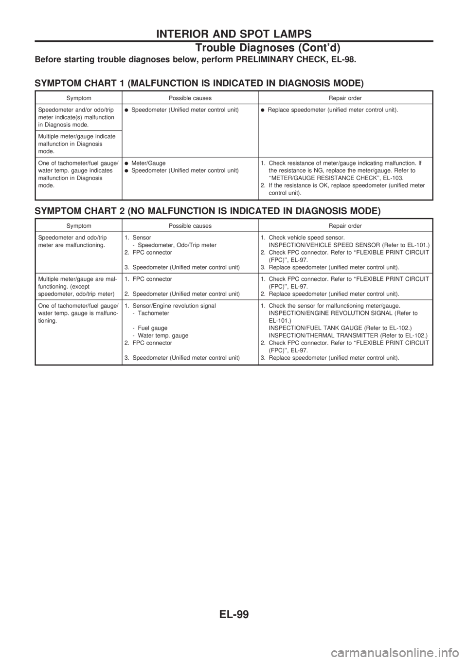
Before starting trouble diagnoses below, perform PRELIMINARY CHECK, EL-98.
SYMPTOM CHART 1 (MALFUNCTION IS INDICATED IN DIAGNOSIS MODE)
Symptom Possible causes Repair order
Speedometer and/or odo/trip
meter indicate(s) malfunction
in Diagnosis mode.
lSpeedometer (Unified meter control unit)lReplace speedometer (unified meter control unit).
Multiple meter/gauge indicate
malfunction in Diagnosis
mode.
One of tachometer/fuel gauge/
water temp. gauge indicates
malfunction in Diagnosis
mode.
lMeter/GaugelSpeedometer (Unified meter control unit)1. Check resistance of meter/gauge indicating malfunction. If
the resistance is NG, replace the meter/gauge. Refer to
``METER/GAUGE RESISTANCE CHECK'', EL-103.
2. If the resistance is OK, replace speedometer (unified meter
control unit).
SYMPTOM CHART 2 (NO MALFUNCTION IS INDICATED IN DIAGNOSIS MODE)
Symptom Possible causes Repair order
Speedometer and odo/trip
meter are malfunctioning.1. Sensor
- Speedometer, Odo/Trip meter
2. FPC connector
3. Speedometer (Unified meter control unit)1. Check vehicle speed sensor.
INSPECTION/VEHICLE SPEED SENSOR (Refer to EL-101.)
2. Check FPC connector. Refer to ``FLEXIBLE PRINT CIRCUIT
(FPC)'', EL-97.
3. Replace speedometer (unified meter control unit).
Multiple meter/gauge are mal-
functioning. (except
speedometer, odo/trip meter)1. FPC connector
2. Speedometer (Unified meter control unit)1. Check FPC connector. Refer to ``FLEXIBLE PRINT CIRCUIT
(FPC)'', EL-97.
2. Replace speedometer (unified meter control unit).
One of tachometer/fuel gauge/
water temp. gauge is malfunc-
tioning.1. Sensor/Engine revolution signal
- Tachometer
- Fuel gauge
- Water temp. gauge
2. FPC connector
3. Speedometer (Unified meter control unit)1. Check the sensor for malfunctioning meter/gauge.
INSPECTION/ENGINE REVOLUTION SIGNAL (Refer to
EL-101.)
INSPECTION/FUEL TANK GAUGE (Refer to EL-102.)
INSPECTION/THERMAL TRANSMITTER (Refer to EL-102.)
2. Check FPC connector. Refer to ``FLEXIBLE PRINT CIRCUIT
(FPC)'', EL-97.
3. Replace speedometer (unified meter control unit).
INTERIOR AND SPOT LAMPS
Trouble Diagnoses (Cont'd)
EL-99
Page 1399 of 1659
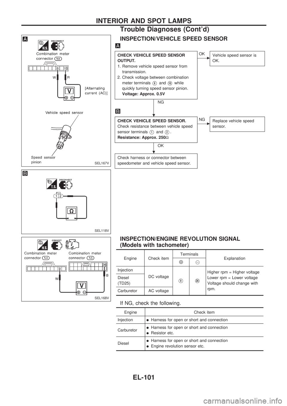
INSPECTION/VEHICLE SPEED SENSOR
CHECK VEHICLE SPEED SENSOR
OUTPUT.
1. Remove vehicle speed sensor from
transmission.
2. Check voltage between combination
meter terminals
V8andV10while
quickly turning speed sensor pinion.
Voltage: Approx. 0.5V
NG
cOK
Vehicle speed sensor is
OK.
CHECK VEHICLE SPEED SENSOR.
Check resistance between vehicle speed
sensor terminals
V1andV2.
Resistance: Approx. 250W
OK
cNG
Replace vehicle speed
sensor.
Check harness or connector between
speedometer and vehicle speed sensor.
INSPECTION/ENGINE REVOLUTION SIGNAL
(Models with tachometer)
Engine Check itemTerminals
ExplanationÅ@
Injection
DC voltage
V9V26
Higher rpm = Higher voltage
Lower rpm = Lower voltage
Voltage should change with
rpm. Diesel
(TD25)
Carburetor AC voltage
If NG, check the following.
Engine Check item
Injection
lHarness for open or short and connection
Carburetor
lHarness for open or short and connection
lResistor etc.
Diesel
lHarness for open or short and connection
lEngine revolution sensor etc.
SEL167V
SEL118V
SEL168V
.
.
INTERIOR AND SPOT LAMPS
Trouble Diagnoses (Cont'd)
EL-101
Page 1414 of 1659
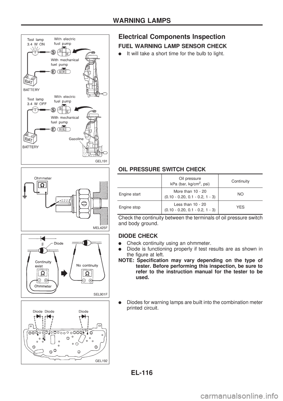
Electrical Components Inspection
FUEL WARNING LAMP SENSOR CHECK
lIt will take a short time for the bulb to light.
OIL PRESSURE SWITCH CHECK
Oil pressure
kPa (bar, kg/cm2, psi)Continuity
Engine startMore than 10 - 20
(0.10 - 0.20, 0.1 - 0.2,1-3)NO
Engine stopLess than 10 - 20
(0.10 - 0.20, 0.1 - 0.2,1-3)YES
Check the continuity between the terminals of oil pressure switch
and body ground.
DIODE CHECK
lCheck continuity using an ohmmeter.
lDiode is functioning properly if test results are as shown in
the figure at left.
NOTE: Specification may vary depending on the type of
tester. Before performing this inspection, be sure to
refer to the instruction manual for the tester to be
used.
lDiodes for warning lamps are built into the combination meter
printed circuit.
GEL191
MEL425F
SEL901F
GEL192
WARNING LAMPS
EL-116
Page 1440 of 1659
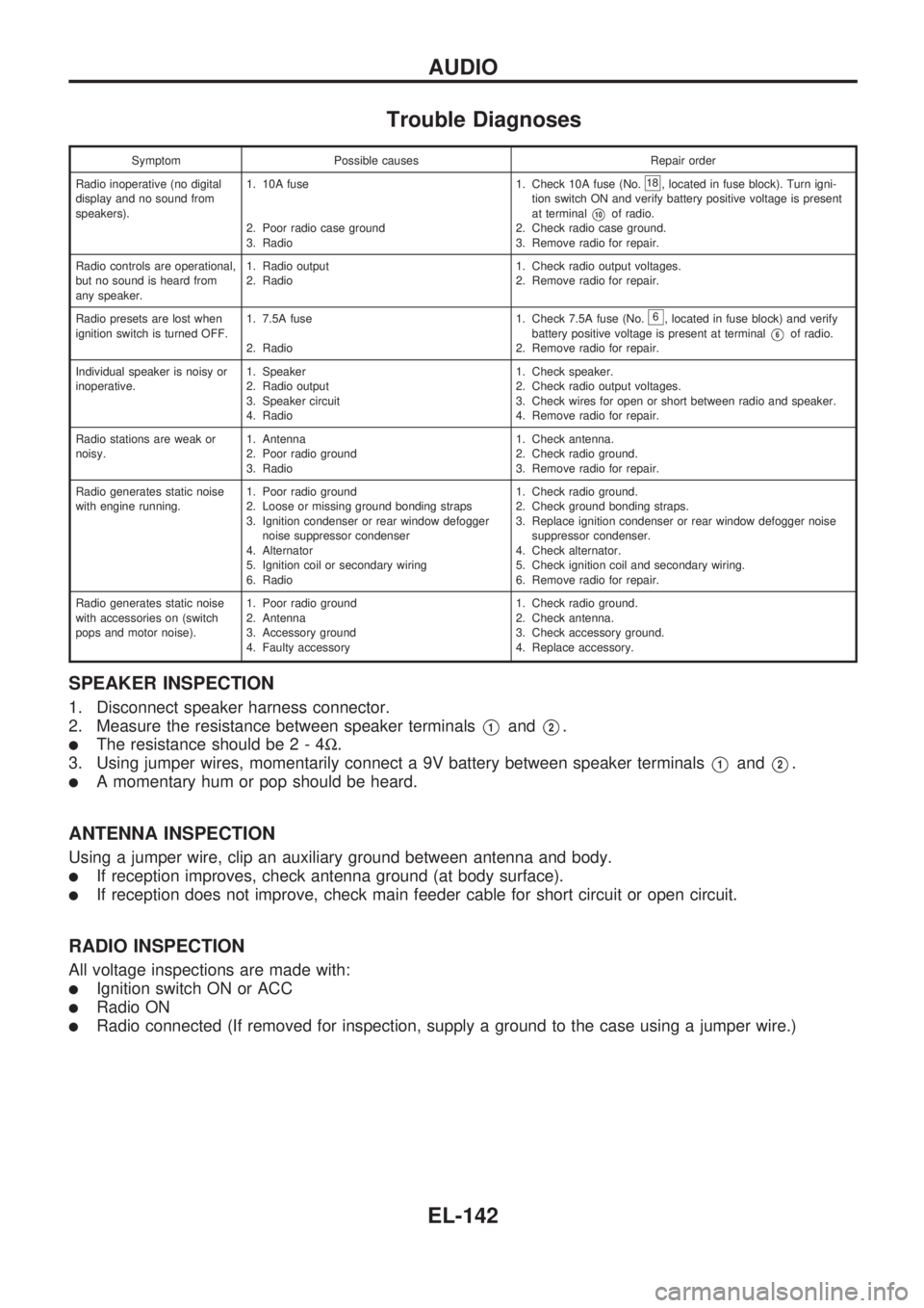
Trouble Diagnoses
Symptom Possible causes Repair order
Radio inoperative (no digital
display and no sound from
speakers).1. 10A fuse
2. Poor radio case ground
3. Radio1. Check 10A fuse (No.
18, located in fuse block). Turn igni-
tion switch ON and verify battery positive voltage is present
at terminal
V10of radio.
2. Check radio case ground.
3. Remove radio for repair.
Radio controls are operational,
but no sound is heard from
any speaker.1. Radio output
2. Radio1. Check radio output voltages.
2. Remove radio for repair.
Radio presets are lost when
ignition switch is turned OFF.1. 7.5A fuse
2. Radio1. Check 7.5A fuse (No.
6, located in fuse block) and verify
battery positive voltage is present at terminal
V6of radio.
2. Remove radio for repair.
Individual speaker is noisy or
inoperative.1. Speaker
2. Radio output
3. Speaker circuit
4. Radio1. Check speaker.
2. Check radio output voltages.
3. Check wires for open or short between radio and speaker.
4. Remove radio for repair.
Radio stations are weak or
noisy.1. Antenna
2. Poor radio ground
3. Radio1. Check antenna.
2. Check radio ground.
3. Remove radio for repair.
Radio generates static noise
with engine running.1. Poor radio ground
2. Loose or missing ground bonding straps
3. Ignition condenser or rear window defogger
noise suppressor condenser
4. Alternator
5. Ignition coil or secondary wiring
6. Radio1. Check radio ground.
2. Check ground bonding straps.
3. Replace ignition condenser or rear window defogger noise
suppressor condenser.
4. Check alternator.
5. Check ignition coil and secondary wiring.
6. Remove radio for repair.
Radio generates static noise
with accessories on (switch
pops and motor noise).1. Poor radio ground
2. Antenna
3. Accessory ground
4. Faulty accessory1. Check radio ground.
2. Check antenna.
3. Check accessory ground.
4. Replace accessory.
SPEAKER INSPECTION
1. Disconnect speaker harness connector.
2. Measure the resistance between speaker terminals
V1andV2.
lThe resistance should be2-4W.
3. Using jumper wires, momentarily connect a 9V battery between speaker terminals
V1andV2.
lA momentary hum or pop should be heard.
ANTENNA INSPECTION
Using a jumper wire, clip an auxiliary ground between antenna and body.
lIf reception improves, check antenna ground (at body surface).
lIf reception does not improve, check main feeder cable for short circuit or open circuit.
RADIO INSPECTION
All voltage inspections are made with:
lIgnition switch ON or ACC
lRadio ON
lRadio connected (If removed for inspection, supply a ground to the case using a jumper wire.)
AUDIO
EL-142