1998 NISSAN PICK-UP check engine
[x] Cancel search: check enginePage 837 of 1659

KEY TO SYMBOLS SIGNIFYING MEASUREMENTS OR PROCEDURES
Symbol Symbol explanation Symbol Symbol explanation
Check after disconnecting the connector
to be measured.Procedure with CONSULT
Check after connecting the connector to
be measured.Procedure without CONSULT
Insert key into ignition switch.A/C switch is ``OFF''.
Remove key from ignition switch.A/C switch is ``ON''.
Turn ignition switch to ``OFF'' position.Fan switch is ``ON''. (At any position
except for ``OFF'' position)
Turn ignition switch to ``ON'' position.Fan switch is ``OFF''.
Turn ignition switch to ``START'' position.Apply positive voltage from battery with
fuse directly to components.
Turn ignition switch from ``OFF'' to ``ACC''
position.Drive vehicle.
Turn ignition switch from ``ACC'' to ``OFF''
position.Disconnect battery negative cable.
Turn ignition switch from ``OFF'' to ``ON''
position.Depress brake pedal.
Turn ignition switch from ``ON'' to ``OFF''
position.Release brake pedal.
Do not start engine, or check with engine
stopped.Depress accelerator pedal.
Start engine, or check with engine run-
ning.Release accelerator pedal.
Apply parking brake.
Pin terminal check for SMJ type ECM
and TCM control unit connectors.
For details regarding the terminal
arrangement, refer to the foldout page.Release parking brake.
Check after engine is warmed up suffi-
ciently.
Voltage should be measured with a volt-
meter.
Circuit resistance should be measured
with an ohmmeter.
Current should be measured with an
ammeter.
HOW TO FOLLOW FLOW CHART IN TROUBLE DIAGNOSES
How to Follow This Flow Chart (Cont'd)
GI-33
Page 860 of 1659
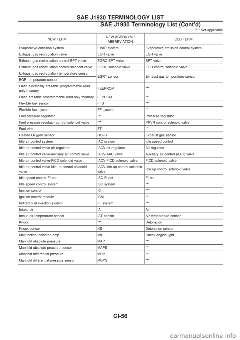
***: Not applicable
NEW TERMNEW ACRONYM /
ABBREVIATIONOLD TERM
Evaporative emission system EVAP system Evaporative emission control system
Exhaust gas recirculation valve EGR valve EGR valve
Exhaust gas recirculation control-BPT valve EGRC-BPT valve BPT valve
Exhaust gas recirculation control-solenoid valve EGRC-solenoid valve EGR control solenoid valve
Exhaust gas recirculation temperature sensor
EGRT sensor Exhaust gas temperature sensor
EGR temperature sensor
Flash electrically erasable programmable read
only memoryFEEPROM ***
Flash erasable programmable read only memory FEPROM ***
Flexible fuel sensor FFS ***
Flexible fuel system FF system ***
Fuel pressure regulator *** Pressure regulator
Fuel pressure regulator control solenoid valve *** PRVR control solenoid valve
Fuel trim FT ***
Heated Oxygen sensor HO2S Exhaust gas sensor
Idle air control system IAC system Idle speed control
Idle air control valve-air regulator IACV-air regulator Air regulator
Idle air control valve-auxiliary air control valve IACV-AAC valve Auxiliary air control (AAC) valve
Idle air control valve-FICD solenoid valve IACV-FICD solenoid valve FICD solenoid valve
Idle air control valve-idle up control solenoid
valveIACV-idle up control solenoid
valveIdle up control solenoid valve
Idle speed control-FI pot ISC-FI pot FI pot
Idle speed control system ISC system ***
Ignition control IC ***
Ignition control module ICM ***
Indirect fuel injection system IFI system ***
Intake air IA Air
Intake air temperature sensor IAT sensor Air temperature sensor
Knock *** Detonation
Knock sensor KS Detonation sensor
Malfunction indicator lamp MIL Check engine light
Manifold absolute pressure MAP ***
Manifold absolute pressure sensor MAPS ***
Manifold differential pressure MDP ***
Manifold differential pressure sensor MDPS ***
SAE J1930 TERMINOLOGY LIST
SAE J1930 Terminology List (Cont'd)
GI-56
Page 864 of 1659
A
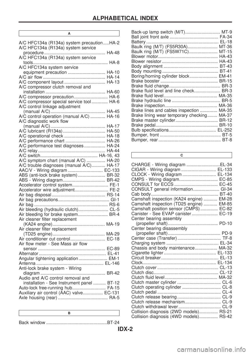
A/C HFC134a (R134a) system precaution .....HA-2
A/C HFC134a (R134a) system service
procedure ................................................. HA-48
A/C HFC134a (R134a) system service
tools............................................................ HA-8
A/C HFC134a system service
equipment precaution .............................. HA-10
A/C air flow .................................................. HA-14
A/C component layout ................................. HA-13
A/C compressor clutch removal and
installation ................................................ HA-60
A/C compressor precaution ........................... HA-6
A/C compressor special service tool ............. HA-6
A/C control linkage adjustment
(manual A/C) ............................................ HA-45
A/C control operation (manual A/C) ............ HA-16
A/C diagnostic work flow
(manual A/C) ............................................ HA-17
A/C lubricant (R134a) .................................. HA-50
A/C operational check ................................. HA-18
A/C performance chart ................................ HA-26
A/C performance test diagnoses ................. HA-24
A/C relay ...................................................... HA-44
A/C switch.............................................. HA-16, 43
A/C symptom chart (manual A/C) ............... HA-20
A/C trouble diagnoses (manual A/C)........... HA-17
AAC/V - Wiring diagram ............................ EC-133
ABS (anti-lock brake system) ...................... BR-32
ABS - Wiring diagram .................................. BR-42
Accelerator control system............................. FE-1
Accelerator wire adjustment........................... FE-2
Air bag disposal ........................................... RS-14
Air bag precautions ......................................... GI-1
Air bag ........................................................... RS-6
Air bleeding (hydraulic clutch)........................ CL-5
Air bleeding for brake system........................ BR-4
Air cleaner filter replacement
(KA24 engine).......................................... MA-19
Air cleaner filter replacement
(TD25 engine).......................................... MA-29
Air conditioner cut control ............................ EC-18
Air flow meter - See Mass air flow
sensor ...................................................... EC-89
Alternator ...................................................... EL-41
Angular tightening application ....................... EM-1
Antenna ...................................................... EL-146
Anti-lock brake system - Wiring
diagram .................................................... BR-42
Audio and A/C control removal and
installation - See Instrument panel .......... BT-12
Auto-lock free-running hub........................... FA-15
Auxiliary air control (AAC) valve................ EC-131
Axle housing (rear) ........................................ RA-5
B
Back window .................................................BT-24Back-up lamp switch (M/T)............................ MT-9
Ball joint front axle ....................................... FA-34
Battery .......................................................... EL-18
Baulk ring (M/T) (FS5R30A)........................ MT-36
Baulk ring (M/T) (FS5W71C)....................... MT-15
Blower motor................................................ HA-43
Blower resistor ............................................. HA-43
Body alignment ............................................ BT-43
Body mounting ............................................. BT-41
Boring/horning cylinder block ...................... EM-41
Brake booster .............................................. BR-15
Brake fluid change ......................................... BR-3
Brake fluid level and line check..................... BR-3
Brake fluid level ........................................... MA-35
Brake hydraulic line ....................................... BR-5
Brake inspection .......................................... MA-36
Brake lines and cables inspection .............. MA-35
Brake lining wear temporary checking ........ MA-37
Brake master cylinder .................................. BR-12
Brake pedal.................................................. BR-10
Bulb specifications...................................... EL-252
Bumper, front ................................................. BT-5
Bumper, rear .................................................. BT-8
C
CHARGE - Wiring diagram ...........................EL-34
CIGAR - Wiring diagram ............................ EL-133
CLOCK - Wiring diagram ........................... EL-134
CMPS - Wiring diagram............................... EC-85
CONSULT for ECCS ................................... EC-45
CONSULT general information ..................... GI-34
Cab body ...................................................... BT-40
Camshaft inspection (KA24 engine) ........... EM-28
Camshaft inspection (TD25 engine) ........... EM-85
Camshaft position sensor (CMPS) .............. EC-82
Canister - See EVAP canister ..................... EC-19
Center bearing assembly
(propeller shaft) ........................................ PD-10
Center bearing disassembly
(propeller shaft) .......................................... PD-9
Center case (Transfer) ................................... TF-8
Charging system .......................................... EL-34
Chassis and body maintenance .................. MA-32
Cigarette lighter .......................................... EL-133
Circuit breaker .............................................. EL-13
Clock........................................................... EL-134
Clutch cover ................................................. CL-13
Clutch disc.................................................... CL-12
Clutch fluid level .......................................... MA-32
Clutch master cylinder ................................... CL-6
Clutch operating cylinder ............................... CL-8
Clutch pedal ................................................... CL-4
Clutch release bearing ................................... CL-9
Clutch release mechanism............................. CL-9
Clutch withdrawal lever .................................. CL-9
Collision diagnosis (2WD models)............... RS-21
Collision diagnosis (4WD models)............... RS-42
ALPHABETICAL INDEX
IDX-2
Page 866 of 1659

EVAP vapor lines inspection ....................... MA-22
Electrical diagnoses ...................................... GI-21
Engine compartment .................................... BT-44
Engine control module (ECM) ....................... EC-5
Engine coolant temperature sensor
(ECTS) (KA24 engine) ............................. EC-95
Engine coolant temperature sensor
(ECTS) (TD25 engine) ........................... EC-209
Engine oil filter replacement
(KA24 engine).......................................... MA-20
Engine oil filter replacement
(TD25 engine).......................................... MA-24
Engine oil precautions .................................... GI-4
Engine oil replacement
(KA24 engine).......................................... MA-19
Engine oil replacement
(TD25 engine).......................................... MA-24
Engine outer component parts
(KA24 engine)............................................ EM-9
Engine outer component parts
(TD25 engine).......................................... EM-49
Engine removal (KA24 engine) ................... EM-36
Engine removal (TD25 engine) ................... EM-69
Engine room - See Engine
compartment............................................. BT-44
Engine speed sensor ................................. EC-219
Evaporative emission (EVAP) system ......... EC-19
Exhaust system inspection.......................... MA-32
Exhaust system .............................................. FE-5
Exterior ......................................................... BT-24
F
F/PUMP - Wiring diagram...........................EC-153
FCUT - Wiring diagram ............................. EC-225
FICD - Wiring diagram (KA24 engine) ...... EC-168
FICD - Wiring diagram (TD25 engine) ...... EC-230
Fan switch.................................................... HA-43
Fast idle cam (FIC) inspection and
adjustment................................................ EC-24
Final drive disassembly (C200) ................... PD-34
Final drive disassembly (H233B)................. PD-56
Final drive pre-inspection (C200) ................ PD-34
Final drive pre-inspection (H233B) .............. PD-56
Final drive removal and installation ............. PD-15
Floor trim ...................................................... BT-15
Flow charts.................................................... GI-31
Fluids ........................................................... MA-12
Flywheel (clutch) .......................................... CL-12
Flywheel runout (KA24 engine)................... EM-45
Flywheel runout (TD25 engine)................... EM-80
Fog lamp, rear .............................................. EL-72
Fork rod (M/T) (FS5R30A) .......................... MT-38
Fork rod (M/T) (FS5W71C) ......................... MT-17
Front axle ..................................................... FA-12
Front bumper.................................................. BT-5
Front case (Transfer) ..................................... TF-8
Front combination lamp removal and
installation................................................... BT-5Front disc brake ........................................... BR-21
Front door..................................................... BT-10
Front drive shaft (Transfer) ............................ TF-9
Front final drive disassembly (4WD) ........... PD-17
Front final drive pre-inspection (4WD) ........ PD-17
Front final drive removal and installa-
tion (4WD) ................................................ PD-14
Front seat belt................................................ RS-3
Front seat ..................................................... BT-30
Front suspension.......................................... FA-26
Front washer .............................................. EL-120
Front wiper ................................................. EL-120
Fuel check valve .......................................... EC-20
Fuel cut control (at no load & high
engine speed) (KA24 engine) .................. EC-18
Fuel cut control (at no load & high
engine speed) ........................................ EC-225
Fuel filter replacement (KA24 engine) ........ MA-18
Fuel filter replacement (TD25 engine) ........ MA-27
Fuel injector ............................................... EC-144
Fuel line inspection (KA24 engine) ............. MA-18
Fuel line inspection (TD25 engine) ............. MA-28
Fuel precautions ............................................. GI-5
Fuel pressure check .................................... EC-22
Fuel pressure release .................................. EC-22
Fuel pump .................................................. EC-151
Fuel pump relay ......................................... EC-156
Fuel system .................................................... FE-3
Fuel tank vacuum relief valve...................... EC-20
Fuse block.................................................. Foldout
Fuse.............................................................. EL-13
Fusible link ................................................... EL-13G
GLOW - Wiring diagram .............................EC-197
Garage jack and safety stand....................... GI-49
Gear components (M/T) (FS5R30A) ........... MT-36
Gear components (M/T) (FS5W71C) .......... MT-15
Glass ............................................................ BT-10
Glow plug ................................................... EC-208
Glow relay .................................................. EC-208
Grease ......................................................... MA-12
Ground clearance ......................................... GI-44
Ground distribution ....................................... EL-14
H
H/AIM - Wiring diagram .................................EL-64
H/LAMP - Wiring diagram ............................ EL-44
H02S - Wiring diagram .............................. EC-124
HFC134a (R134a) system precaution ........... HA-2
HFC134a (R134a) system service
procedure ................................................. HA-48
HFC134a (R134a) system service
tools............................................................ HA-8
HFC134a system service equipment
precaution ................................................ HA-10
ALPHABETICAL INDEX
IDX-4
Page 868 of 1659
Maintenance (engine) (TD25 engine) ......... MA-23
Major overhaul (Transfer)............................... TF-8
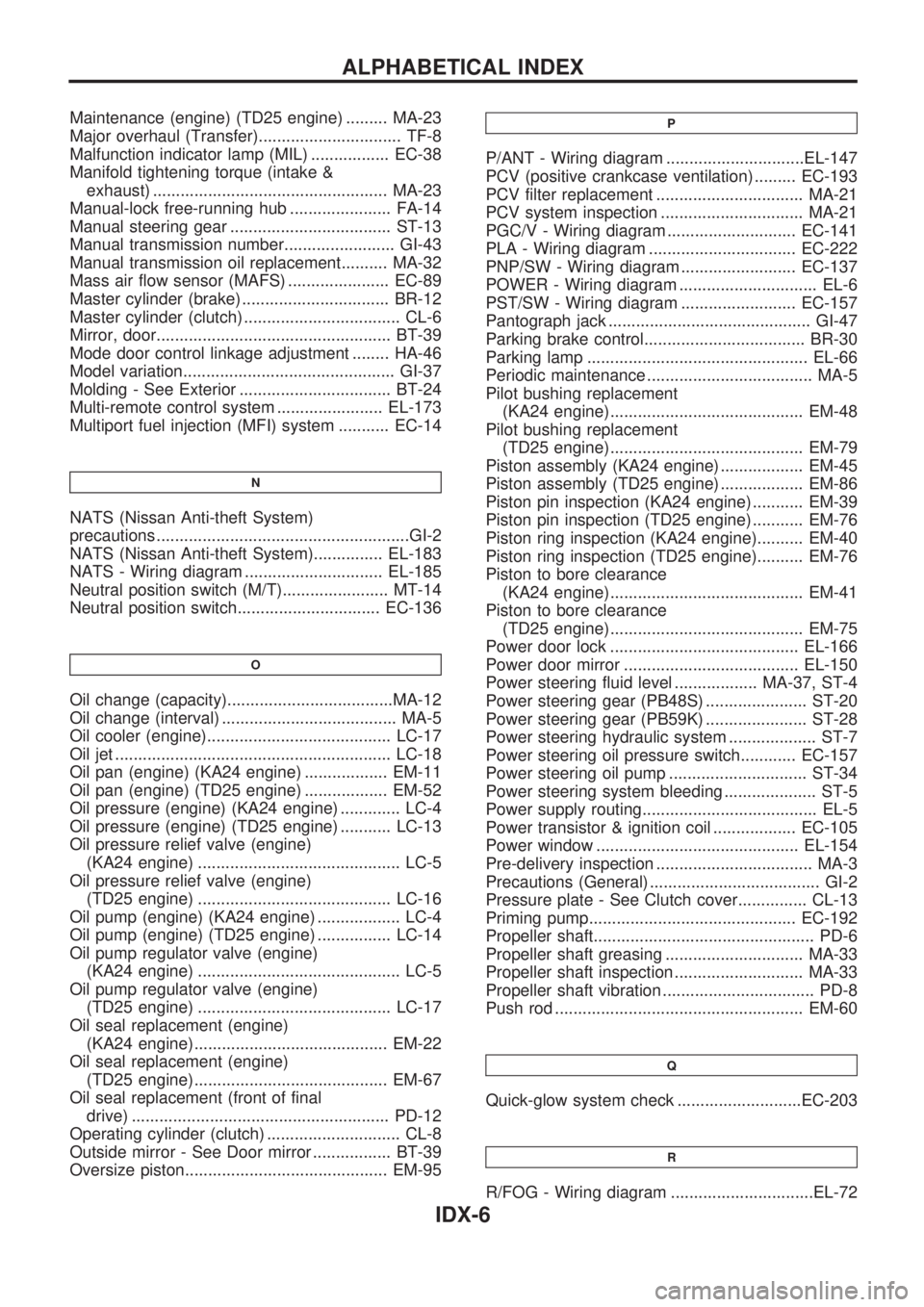
Malfunction indicator lamp (MIL) ................. EC-38
Manifold tightening torque (intake &
exhaust) ................................................... MA-23
Manual-lock free-running hub ...................... FA-14
Manual steering gear ................................... ST-13
Manual transmission number........................ GI-43
Manual transmission oil replacement.......... MA-32
Mass air flow sensor (MAFS) ...................... EC-89
Master cylinder (brake) ................................ BR-12
Master cylinder (clutch) .................................. CL-6
Mirror, door................................................... BT-39
Mode door control linkage adjustment ........ HA-46
Model variation.............................................. GI-37
Molding - See Exterior ................................. BT-24
Multi-remote control system ....................... EL-173
Multiport fuel injection (MFI) system ........... EC-14
N
NATS (Nissan Anti-theft System)
precautions .......................................................GI-2
NATS (Nissan Anti-theft System)............... EL-183
NATS - Wiring diagram .............................. EL-185
Neutral position switch (M/T)....................... MT-14
Neutral position switch............................... EC-136
O
Oil change (capacity)....................................MA-12
Oil change (interval) ...................................... MA-5
Oil cooler (engine)........................................ LC-17
Oil jet ............................................................ LC-18
Oil pan (engine) (KA24 engine) .................. EM-11
Oil pan (engine) (TD25 engine) .................. EM-52
Oil pressure (engine) (KA24 engine) ............. LC-4
Oil pressure (engine) (TD25 engine) ........... LC-13
Oil pressure relief valve (engine)
(KA24 engine) ............................................ LC-5
Oil pressure relief valve (engine)
(TD25 engine) .......................................... LC-16
Oil pump (engine) (KA24 engine) .................. LC-4
Oil pump (engine) (TD25 engine) ................ LC-14
Oil pump regulator valve (engine)
(KA24 engine) ............................................ LC-5
Oil pump regulator valve (engine)
(TD25 engine) .......................................... LC-17
Oil seal replacement (engine)
(KA24 engine).......................................... EM-22
Oil seal replacement (engine)
(TD25 engine).......................................... EM-67
Oil seal replacement (front of final
drive) ........................................................ PD-12
Operating cylinder (clutch) ............................. CL-8
Outside mirror - See Door mirror ................. BT-39
Oversize piston............................................ EM-95
P
P/ANT - Wiring diagram ..............................EL-147
PCV (positive crankcase ventilation) ......... EC-193
PCV filter replacement ................................ MA-21
PCV system inspection ............................... MA-21
PGC/V - Wiring diagram ............................ EC-141
PLA - Wiring diagram ................................ EC-222
PNP/SW - Wiring diagram ......................... EC-137
POWER - Wiring diagram .............................. EL-6
PST/SW - Wiring diagram ......................... EC-157
Pantograph jack ............................................ GI-47
Parking brake control................................... BR-30
Parking lamp ................................................ EL-66
Periodic maintenance .................................... MA-5
Pilot bushing replacement
(KA24 engine).......................................... EM-48
Pilot bushing replacement
(TD25 engine).......................................... EM-79
Piston assembly (KA24 engine) .................. EM-45
Piston assembly (TD25 engine) .................. EM-86
Piston pin inspection (KA24 engine) ........... EM-39
Piston pin inspection (TD25 engine) ........... EM-76
Piston ring inspection (KA24 engine).......... EM-40
Piston ring inspection (TD25 engine).......... EM-76
Piston to bore clearance
(KA24 engine).......................................... EM-41
Piston to bore clearance
(TD25 engine).......................................... EM-75
Power door lock ......................................... EL-166
Power door mirror ...................................... EL-150
Power steering fluid level .................. MA-37, ST-4
Power steering gear (PB48S) ...................... ST-20
Power steering gear (PB59K) ...................... ST-28
Power steering hydraulic system ................... ST-7
Power steering oil pressure switch............ EC-157
Power steering oil pump .............................. ST-34
Power steering system bleeding .................... ST-5
Power supply routing...................................... EL-5
Power transistor & ignition coil .................. EC-105
Power window ............................................ EL-154
Pre-delivery inspection .................................. MA-3
Precautions (General) ..................................... GI-2
Pressure plate - See Clutch cover............... CL-13
Priming pump............................................. EC-192
Propeller shaft................................................ PD-6
Propeller shaft greasing .............................. MA-33
Propeller shaft inspection ............................ MA-33
Propeller shaft vibration ................................. PD-8
Push rod ...................................................... EM-60
Q
Quick-glow system check ...........................EC-203
R
R/FOG - Wiring diagram ...............................EL-72
ALPHABETICAL INDEX
IDX-6
Page 877 of 1659
Precautions for Servicing Compressor
lPlug all openings to prevent moisture and foreign matter from entering.
lWhen the compressor is removed, store it in the same position as it is when mounted on the car.
lWhen replacing or repairing compressor, follow ``Maintenance of Lubricant Quantity in Compres-
sor'' exactly. Refer to HA-50.
lKeep friction surfaces between clutch and pulley clean. If the surface is contaminated, with
lubricant, wipe it off by using a clean waste cloth moistened with thinner.
lAfter compressor service operation, turn the compressor shaft by hand more than five turns in
both directions. This will equally distribute lubricant inside the compressor. After the compres-
sor is installed, let the engine idle and operate the compressor for one hour.
lAfter replacing the compressor magnet clutch, apply voltage to the new one and check for nor-
mal operation.
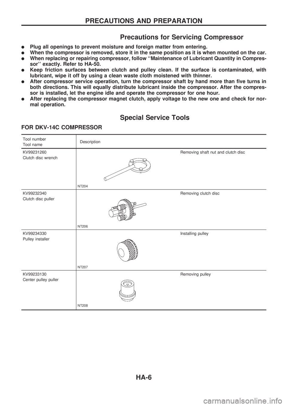
Special Service Tools
FOR DKV-14C COMPRESSOR
Tool number
Tool nameDescription
KV99231260
Clutch disc wrench
NT204
Removing shaft nut and clutch disc
KV99232340
Clutch disc puller
NT206
Removing clutch disc
KV99234330
Pulley installer
NT207
Installing pulley
KV99233130
Center pulley puller
NT208
Removing pulley
PRECAUTIONS AND PREPARATION
HA-6
Page 889 of 1659
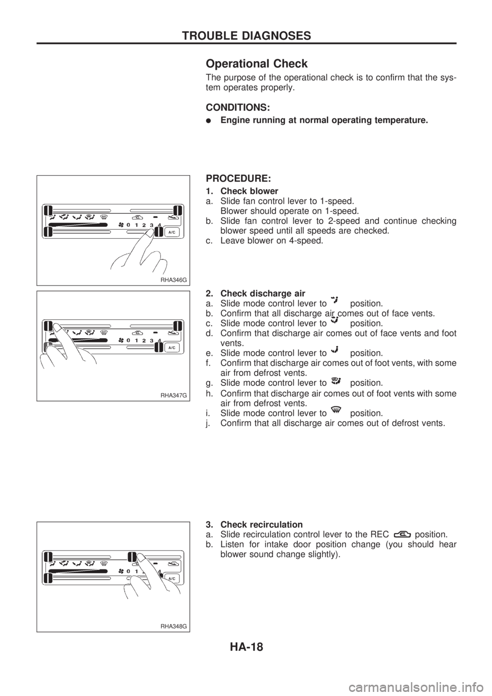
Operational Check
The purpose of the operational check is to confirm that the sys-
tem operates properly.
CONDITIONS:
lEngine running at normal operating temperature.
PROCEDURE:
1. Check blower
a. Slide fan control lever to 1-speed.
Blower should operate on 1-speed.
b. Slide fan control lever to 2-speed and continue checking
blower speed until all speeds are checked.
c. Leave blower on 4-speed.
2. Check discharge air
a. Slide mode control lever to
position.
b. Confirm that all discharge air comes out of face vents.
c. Slide mode control lever to
position.
d. Confirm that discharge air comes out of face vents and foot
vents.
e. Slide mode control lever to
position.
f. Confirm that discharge air comes out of foot vents, with some
air from defrost vents.
g. Slide mode control lever to
position.
h. Confirm that discharge air comes out of foot vents with some
air from defrost vents.
i. Slide mode control lever to
position.
j. Confirm that all discharge air comes out of defrost vents.
3. Check recirculation
a. Slide recirculation control lever to the REC
position.
b. Listen for intake door position change (you should hear
blower sound change slightly).
RHA346G
RHA347G
RHA348G
TROUBLE DIAGNOSES
HA-18
Page 892 of 1659
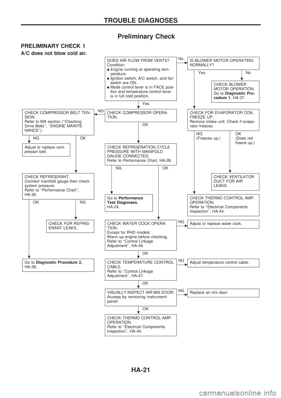
Preliminary Check
PRELIMINARY CHECK 1
A/C does not blow cold air.
DOES AIR FLOW FROM VENTS?
Condition:
lEngine running at operating tem-
perature.
lIgnition switch, A/C switch, and fan
switch are ON.
lMode control lever is in FACE posi-
tion and temperature control lever
is in full cold position.
Yes
cNo
IS BLOWER MOTOR OPERATING
NORMALLY?
Yes No
CHECK BLOWER
MOTOR OPERATION.
Go toDiagnostic Pro-
cedure 1, HA-37.
CHECK COMPRESSOR BELT TEN-
SION.
Refer to MA section (``Checking
Drive Belts'', ``ENGINE MAINTE-
NANCE'').
NG OKNG
bCHECK COMPRESSOR OPERA-
TION.
OKCHECK FOR EVAPORATOR COIL
FREEZE UP.
Remove intake unit. Check if evapo-
rator freezes.
Adjust or replace com-
pressor belt.CHECK REFRIGERATION CYCLE
PRESSURE WITH MANIFOLD
GAUGE CONNECTED.
Refer to Performance Chart, HA-26.
NG OKNG
(Freezes up.)OK
(Does not
freeze up.)
CHECK REFRIGERANT.
Connect manifold gauge then check
system pressure.
Refer to ``Performance Chart'',
HA-26.
OK NGCHECK VENTILATOR
DUCT FOR AIR
LEAKS.Go toPerformance
Test Diagnoses,
HA-24.CHECK THERMO CONTROL AMP.
OPERATION.
Refer to ``Electrical Components
Inspection'', HA-44.
CHECK FOR REFRIG-
ERANT LEAKS.CHECK WATER COCK OPERA-
TION.
Except for RHD models
Warm up engine before checking.
Refer to ``Control Linkage
Adjustment'', HA-46.
OK
cNG
Adjust or replace water cock.
Go toDiagnostic Procedure 2,
HA-39.CHECK TEMPERATURE CONTROL
CABLE.
Refer to ``Control Linkage
Adjustment'', HA-47.
OK
cNG
Adjust temperature control cable.
VISUALLY INSPECT AIR MIX DOOR.Access by removing instrument
panel.
OK
cNG
Replace air mix door.
CHECK THERMO CONTROL AMP.
OPERATION.
Refer to ``Electrical Components
Inspection'', HA-44.
.
..
..
..
..
..
..
.
.
TROUBLE DIAGNOSES
HA-21