Page 724 of 1659

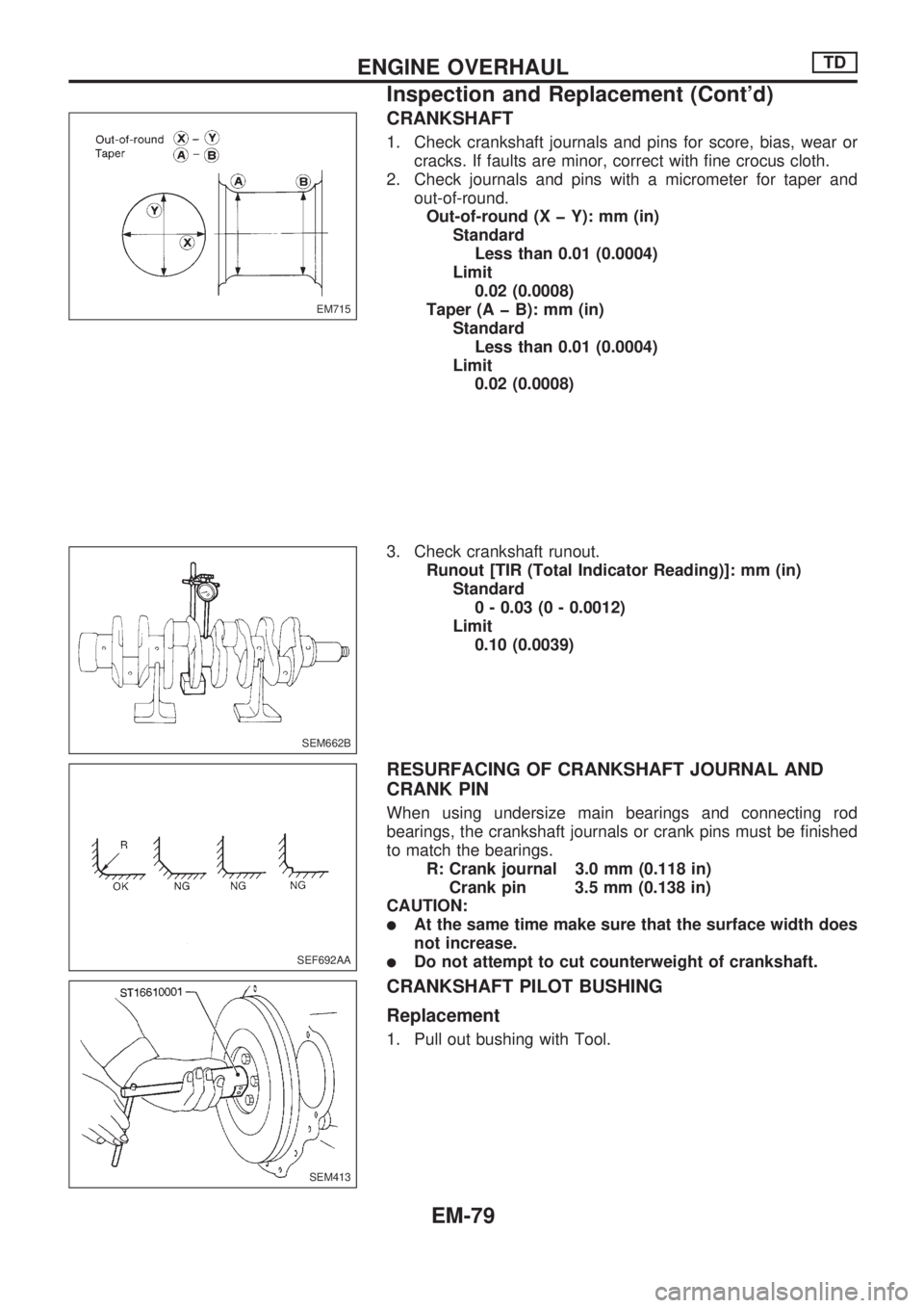
CRANKSHAFT
1. Check crankshaft journals and pins for score, bias, wear or
cracks. If faults are minor, correct with fine crocus cloth.
2. Check journals and pins with a micrometer for taper and
out-of-round.
Out-of-round (X þ Y): mm (in)
Standard
Less than 0.01 (0.0004)
Limit
0.02 (0.0008)
Taper (A þ B): mm (in)
Standard
Less than 0.01 (0.0004)
Limit
0.02 (0.0008)
3. Check crankshaft runout.
Runout [TIR (Total Indicator Reading)]: mm (in)
Standard
0 - 0.03 (0 - 0.0012)
Limit
0.10 (0.0039)
RESURFACING OF CRANKSHAFT JOURNAL AND
CRANK PIN
When using undersize main bearings and connecting rod
bearings, the crankshaft journals or crank pins must be finished
to match the bearings.
R: Crank journal 3.0 mm (0.118 in)
Crank pin 3.5 mm (0.138 in)
CAUTION:
lAt the same time make sure that the surface width does
not increase.
lDo not attempt to cut counterweight of crankshaft.
CRANKSHAFT PILOT BUSHING
Replacement
1. Pull out bushing with Tool.
EM715
SEM662B
SEF692AA
SEM413
ENGINE OVERHAULTD
Inspection and Replacement (Cont'd)
EM-79
Page 725 of 1659
2. Insert pilot bushing until distance between flange end and
bushing is specified value.
Distance:
Approx. 5.6 - 6.0 mm (0.220 - 0.236 in)
FLYWHEEL RUNOUT
Runout (Total indicator reading):
Less than 0.15 mm (0.0059 in)
FRONT PLATE
Check front plate for warpage. If not within the limit, make flat or
replace front plate.
Warpage limit:
0.2 mm (0.008 in)
GEAR TRAIN
Camshaft drive gear, injection pump drive gear, oil
pump gear, idler gear and crankshaft gear
1. If gear tooth and key have scratches or are excessively worn,
replace gear and key.
2. Check gear train backlash before disassembling and after
assembling.
Method A (Using dial gauge)
Method B (Using fuse wire)
If beyond the limit, replace gear.
Backlash: mm (in)
Standard
0.07 - 0.11 (0.0028 - 0.0043)
Limit
0.20 (0.0079)
SEM089-A
SEM059A
SEM668B
DEM051
MEM151A
ENGINE OVERHAULTD
Inspection and Replacement (Cont'd)
EM-80
Page 728 of 1659
lDrive replacer bar until the alignment mark on replacer bar
is aligned with the end of replacer guide.
Remove replacer set.
After installation, check that oil holes in camshaft bushings
are aligned with oil holes in cylinder block.
SEM601C
ENGINE OVERHAULTD
Inspection and Replacement (Cont'd)
EM-83
Page 730 of 1659
lPress the bushing until its front end is 0.5 mm (0.020 in) from
the front surface of the cylinder block.
3. Check camshaft bushing clearance.
Refer to SDS, EM-101.
4. Install new welch plug into rear camshaft bushing hole with
a drift.
Apply liquid sealer.
CAMSHAFT ALIGNMENT
1. Check camshaft journal and cam surface for bend, wear or
damage.
If fault is beyond limit, replace.
2. Check camshaft bend at center journal.
If bend is greater than specified limit, repair or replace cam-
shaft.
Camshaft bend
(Total indicator reading): mm (in)
Standard
Less than 0.02 (0.0008)
Limit
Less than 0.06 (0.0024)
DEM053
SEM987B
SEM034
SEM670B
ENGINE OVERHAULTD
Inspection and Replacement (Cont'd)
EM-85
Page 759 of 1659

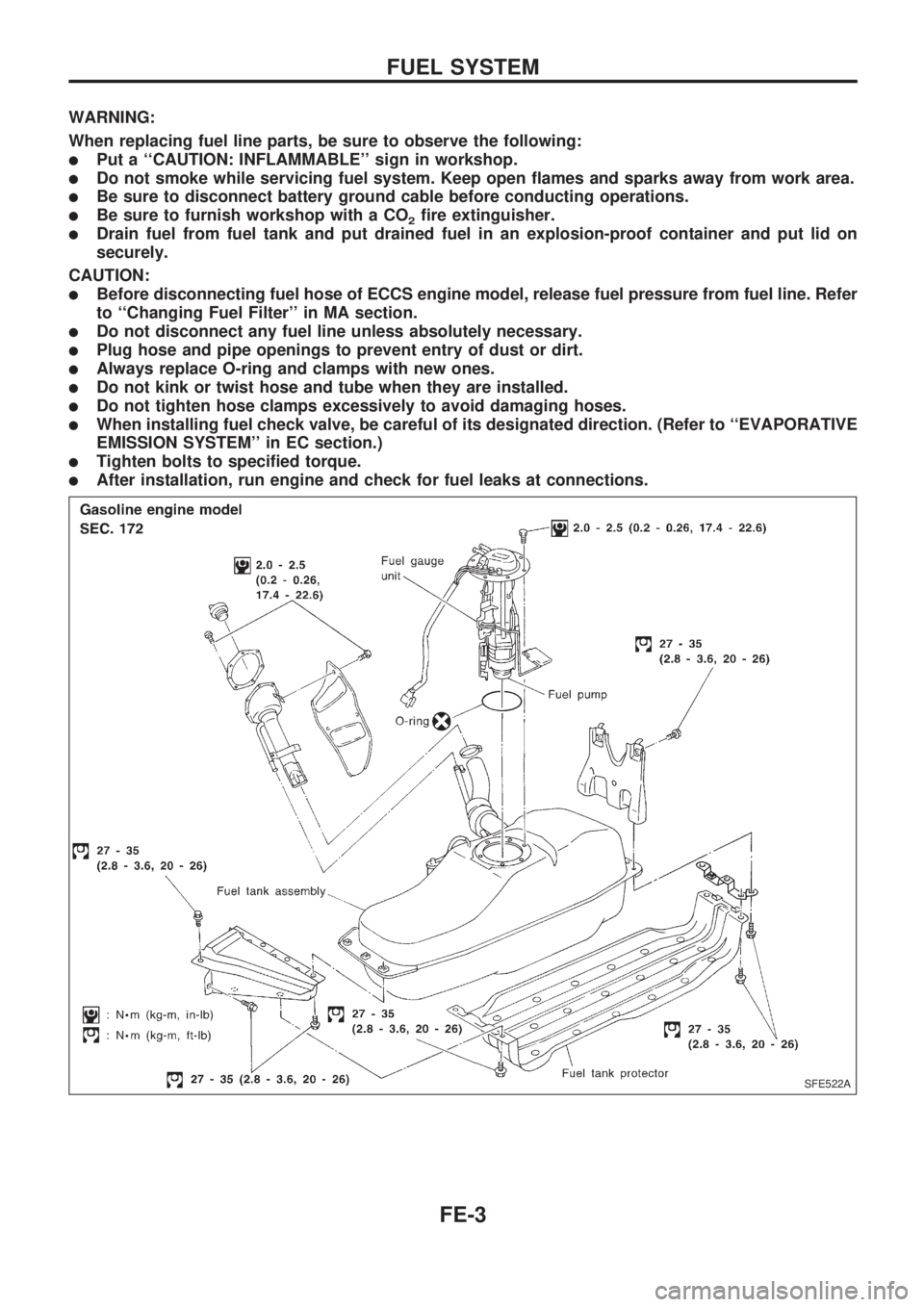
WARNING:
When replacing fuel line parts, be sure to observe the following:
lPut a ``CAUTION: INFLAMMABLE'' sign in workshop.
lDo not smoke while servicing fuel system. Keep open flames and sparks away from work area.
lBe sure to disconnect battery ground cable before conducting operations.
lBe sure to furnish workshop with a CO2fire extinguisher.
lDrain fuel from fuel tank and put drained fuel in an explosion-proof container and put lid on
securely.
CAUTION:
lBefore disconnecting fuel hose of ECCS engine model, release fuel pressure from fuel line. Refer
to ``Changing Fuel Filter'' in MA section.
lDo not disconnect any fuel line unless absolutely necessary.
lPlug hose and pipe openings to prevent entry of dust or dirt.
lAlways replace O-ring and clamps with new ones.
lDo not kink or twist hose and tube when they are installed.
lDo not tighten hose clamps excessively to avoid damaging hoses.
lWhen installing fuel check valve, be careful of its designated direction. (Refer to ``EVAPORATIVE
EMISSION SYSTEM'' in EC section.)
lTighten bolts to specified torque.
lAfter installation, run engine and check for fuel leaks at connections.
SFE522A
FUEL SYSTEM
FE-3
Page 761 of 1659
CAUTION:
lAlways replace exhaust gaskets with new ones when
reassembling. If gasket is left on flange surface, scrape
off completely as shown at left.
lWith engine running, check all tube connections for
exhaust gas leaks, and entire system for unusual noises.
lEnsure that mounting brackets and mounting insulators
are installed properly and free from undue stress.
Improper installation could result in excessive noise or
vibration.
lDiscard any heated oxygen sensor which has been
dropped from a height of more than 0.5 m (19.7 in) onto
a hard surface such as concrete floor; use a new one.
KA24E ENGINE (2WD) MODEL
SEF180A
SFE456A
EXHAUST SYSTEM
FE-5
Page 766 of 1659

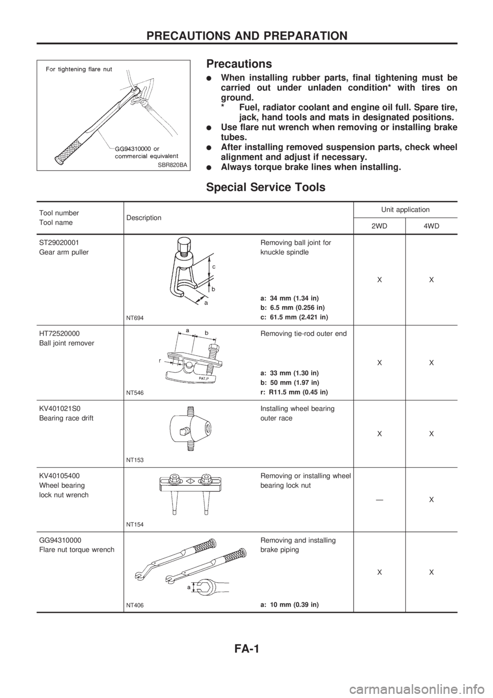
Precautions
lWhen installing rubber parts, final tightening must be
carried out under unladen condition* with tires on
ground.
* Fuel, radiator coolant and engine oil full. Spare tire,
jack, hand tools and mats in designated positions.
lUse flare nut wrench when removing or installing brake
tubes.
lAfter installing removed suspension parts, check wheel
alignment and adjust if necessary.
lAlways torque brake lines when installing.
Special Service Tools
Tool number
Tool nameDescriptionUnit application
2WD 4WD
ST29020001
Gear arm puller
NT694
Removing ball joint for
knuckle spindle
XX
a: 34 mm (1.34 in)
b: 6.5 mm (0.256 in)
c: 61.5 mm (2.421 in)
HT72520000
Ball joint remover
NT546
Removing tie-rod outer end
XX
a: 33 mm (1.30 in)
b: 50 mm (1.97 in)
r: R11.5 mm (0.45 in)
KV401021S0
Bearing race drift
NT153
Installing wheel bearing
outer race
XX
KV40105400
Wheel bearing
lock nut wrench
NT154
Removing or installing wheel
bearing lock nut
ÐX
GG94310000
Flare nut torque wrench
NT406
Removing and installing
brake piping
XX
a: 10 mm (0.39 in)
SBR820BA
PRECAUTIONS AND PREPARATION
FA-1
Page 772 of 1659

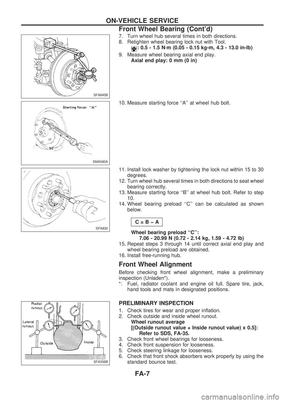
7. Turn wheel hub several times in both directions.
8. Retighten wheel bearing lock nut with Tool.
: 0.5 - 1.5 N´m (0.05 - 0.15 kg-m, 4.3 - 13.0 in-lb)
9. Measure wheel bearing axial end play.
Axial end play: 0 mm (0 in)
10. Measure starting force ``A'' at wheel hub bolt.
11. Install lock washer by tightening the lock nut within 15 to 30
degrees.
12. Turn wheel hub several times in both directions to seat wheel
bearing correctly.
13. Measure starting force ``B'' at wheel hub bolt. Refer to step
10.
14. Wheel bearing preload ``C'' can be calculated as shown
below.
C=BþA
Wheel bearing preload ``C'':
7.06 - 20.99 N (0.72 - 2.14 kg, 1.59 - 4.72 lb)
15. Repeat steps 3 through 14 until correct axial end play and
wheel bearing preload are obtained.
16. Install free-running hub.
Front Wheel Alignment
Before checking front wheel alignment, make a preliminary
inspection (Unladen*).
*: Fuel, radiator coolant and engine oil full. Spare tire, jack,
hand tools and mats in designated positions.
PRELIMINARY INSPECTION
1. Check tires for wear and proper inflation.
2. Check outside and inside wheel runout.
Wheel runout average
[(Outside runout value + Inside runout value) x 0.5]:
Refer to SDS, FA-35.
3. Check front wheel bearings for looseness.
4. Check front suspension for looseness.
5. Check steering linkage for looseness.
6. Check that front shock absorbers work properly by using the
standard bounce test.
SFA845B
SMA580A
SFA830
SFA356B
ON-VEHICLE SERVICE
Front Wheel Bearing (Cont'd)
FA-7