1998 NISSAN PICK-UP check engine
[x] Cancel search: check enginePage 427 of 1659
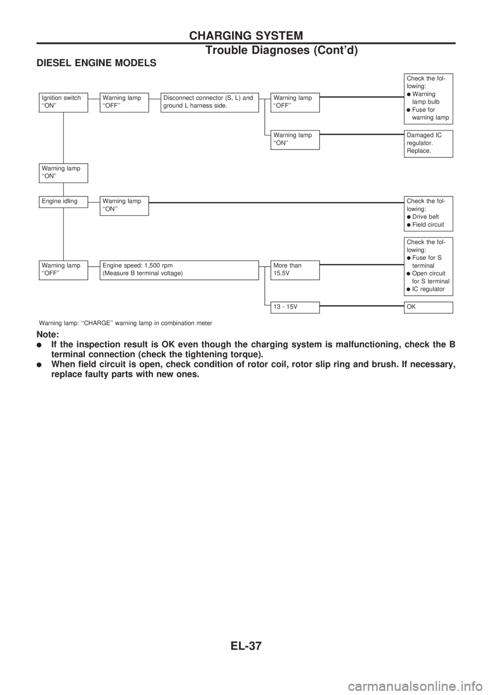
DIESEL ENGINE MODELS
Check the fol-
lowing:
lWarning
lamp bulb
lFuse for
warning lamp
Ignition switch
``ON''Warning lamp
``OFF''Disconnect connector (S, L) and
ground L harness side.Warning lamp
``OFF''
Warning lamp
``ON''Damaged IC
regulator.
Replace.
Warning lamp
``ON''
Engine idlingWarning lamp
``ON''Check the fol-
lowing:
lDrive beltlField circuit
Check the fol-
lowing:
lFuse for S
terminal
lOpen circuit
for S terminal
lIC regulator
Warning lamp
``OFF''Engine speed: 1,500 rpm
(Measure B terminal voltage)More than
15.5V
13 - 15VOK
Warning lamp: ``CHARGE'' warning lamp in combination meter
Note:
lIf the inspection result is OK even though the charging system is malfunctioning, check the B
terminal connection (check the tightening torque).
lWhen field circuit is open, check condition of rotor coil, rotor slip ring and brush. If necessary,
replace faulty parts with new ones.
CHARGING SYSTEM
Trouble Diagnoses (Cont'd)
EL-37
Page 489 of 1659
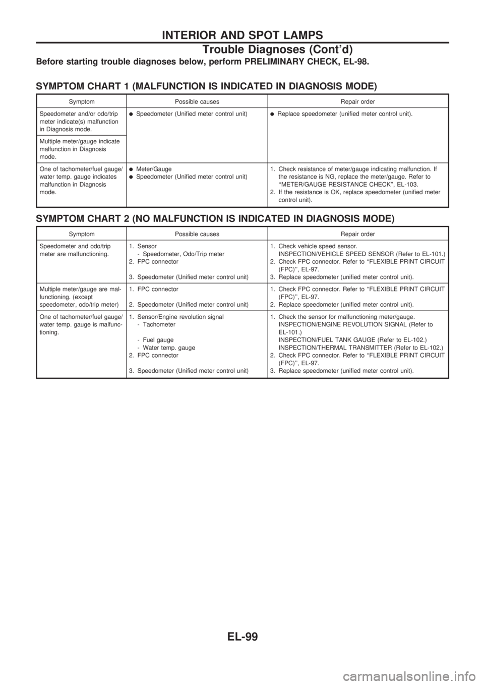
Before starting trouble diagnoses below, perform PRELIMINARY CHECK, EL-98.
SYMPTOM CHART 1 (MALFUNCTION IS INDICATED IN DIAGNOSIS MODE)
Symptom Possible causes Repair order
Speedometer and/or odo/trip
meter indicate(s) malfunction
in Diagnosis mode.
lSpeedometer (Unified meter control unit)lReplace speedometer (unified meter control unit).
Multiple meter/gauge indicate
malfunction in Diagnosis
mode.
One of tachometer/fuel gauge/
water temp. gauge indicates
malfunction in Diagnosis
mode.
lMeter/GaugelSpeedometer (Unified meter control unit)1. Check resistance of meter/gauge indicating malfunction. If
the resistance is NG, replace the meter/gauge. Refer to
``METER/GAUGE RESISTANCE CHECK'', EL-103.
2. If the resistance is OK, replace speedometer (unified meter
control unit).
SYMPTOM CHART 2 (NO MALFUNCTION IS INDICATED IN DIAGNOSIS MODE)
Symptom Possible causes Repair order
Speedometer and odo/trip
meter are malfunctioning.1. Sensor
- Speedometer, Odo/Trip meter
2. FPC connector
3. Speedometer (Unified meter control unit)1. Check vehicle speed sensor.
INSPECTION/VEHICLE SPEED SENSOR (Refer to EL-101.)
2. Check FPC connector. Refer to ``FLEXIBLE PRINT CIRCUIT
(FPC)'', EL-97.
3. Replace speedometer (unified meter control unit).
Multiple meter/gauge are mal-
functioning. (except
speedometer, odo/trip meter)1. FPC connector
2. Speedometer (Unified meter control unit)1. Check FPC connector. Refer to ``FLEXIBLE PRINT CIRCUIT
(FPC)'', EL-97.
2. Replace speedometer (unified meter control unit).
One of tachometer/fuel gauge/
water temp. gauge is malfunc-
tioning.1. Sensor/Engine revolution signal
- Tachometer
- Fuel gauge
- Water temp. gauge
2. FPC connector
3. Speedometer (Unified meter control unit)1. Check the sensor for malfunctioning meter/gauge.
INSPECTION/ENGINE REVOLUTION SIGNAL (Refer to
EL-101.)
INSPECTION/FUEL TANK GAUGE (Refer to EL-102.)
INSPECTION/THERMAL TRANSMITTER (Refer to EL-102.)
2. Check FPC connector. Refer to ``FLEXIBLE PRINT CIRCUIT
(FPC)'', EL-97.
3. Replace speedometer (unified meter control unit).
INTERIOR AND SPOT LAMPS
Trouble Diagnoses (Cont'd)
EL-99
Page 491 of 1659
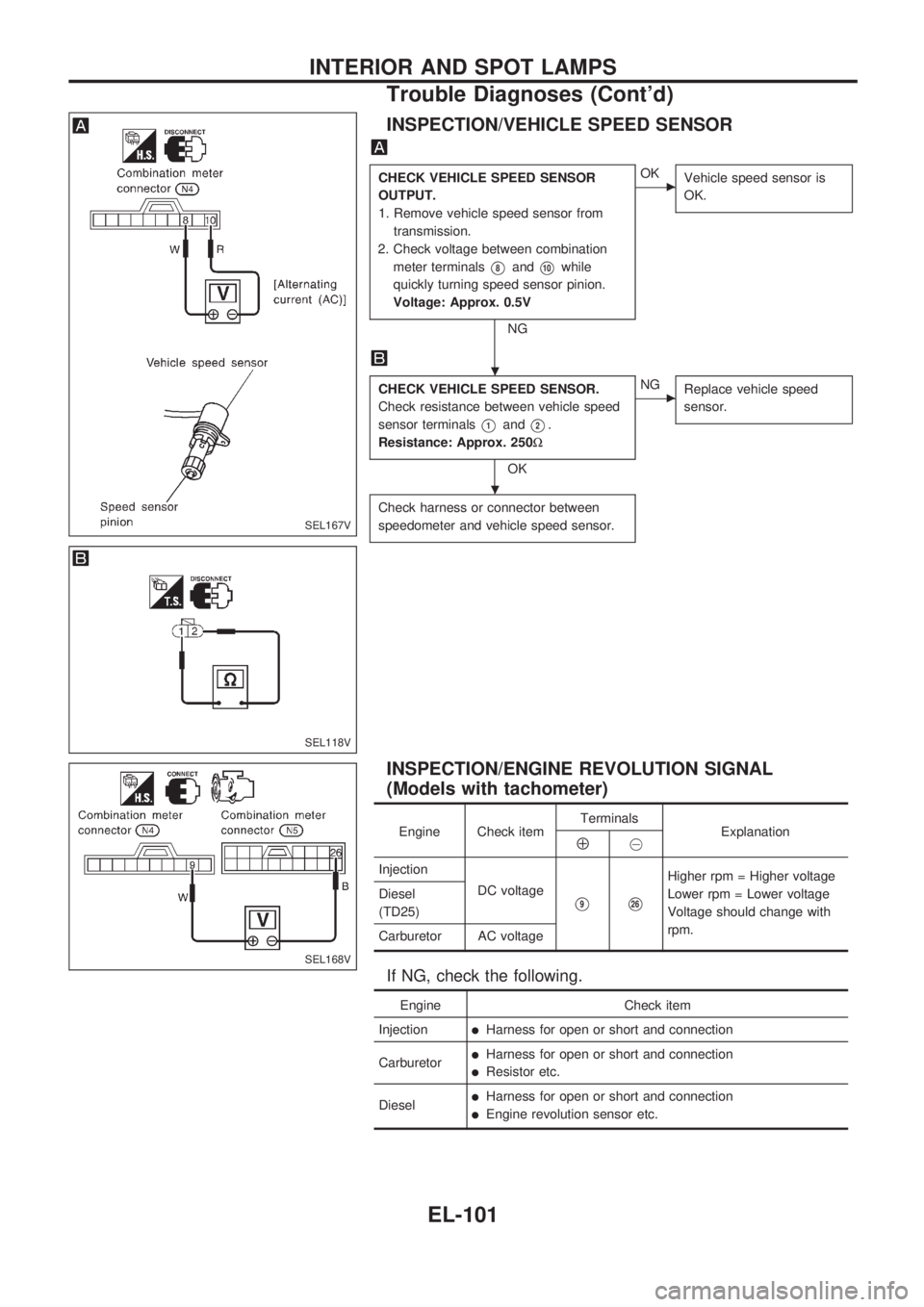
INSPECTION/VEHICLE SPEED SENSOR
CHECK VEHICLE SPEED SENSOR
OUTPUT.
1. Remove vehicle speed sensor from
transmission.
2. Check voltage between combination
meter terminals
V8andV10while
quickly turning speed sensor pinion.
Voltage: Approx. 0.5V
NG
cOK
Vehicle speed sensor is
OK.
CHECK VEHICLE SPEED SENSOR.
Check resistance between vehicle speed
sensor terminals
V1andV2.
Resistance: Approx. 250W
OK
cNG
Replace vehicle speed
sensor.
Check harness or connector between
speedometer and vehicle speed sensor.
INSPECTION/ENGINE REVOLUTION SIGNAL
(Models with tachometer)
Engine Check itemTerminals
ExplanationÅ@
Injection
DC voltage
V9V26
Higher rpm = Higher voltage
Lower rpm = Lower voltage
Voltage should change with
rpm. Diesel
(TD25)
Carburetor AC voltage
If NG, check the following.
Engine Check item
Injection
lHarness for open or short and connection
Carburetor
lHarness for open or short and connection
lResistor etc.
Diesel
lHarness for open or short and connection
lEngine revolution sensor etc.
SEL167V
SEL118V
SEL168V
.
.
INTERIOR AND SPOT LAMPS
Trouble Diagnoses (Cont'd)
EL-101
Page 506 of 1659
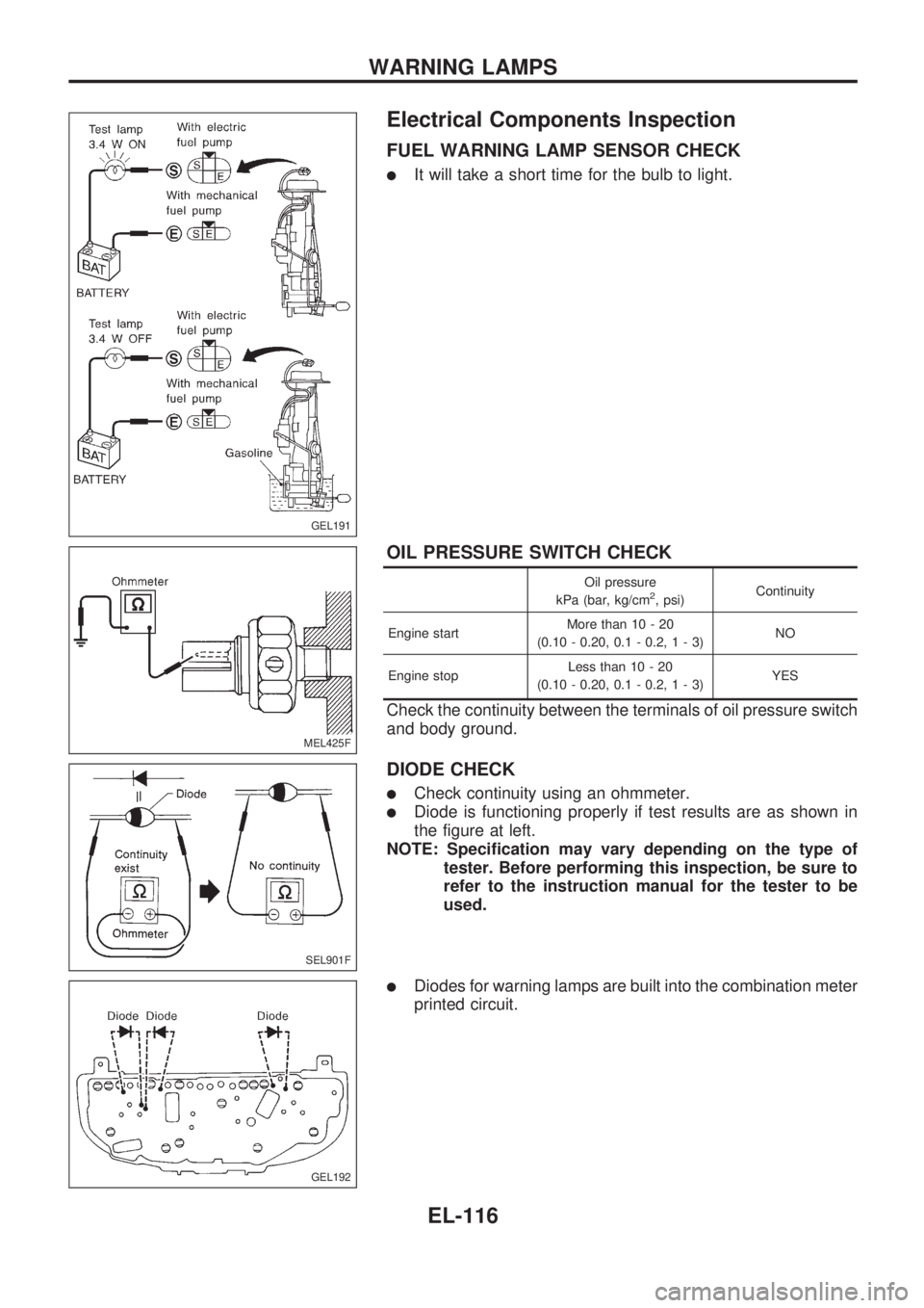
Electrical Components Inspection
FUEL WARNING LAMP SENSOR CHECK
lIt will take a short time for the bulb to light.
OIL PRESSURE SWITCH CHECK
Oil pressure
kPa (bar, kg/cm2, psi)Continuity
Engine startMore than 10 - 20
(0.10 - 0.20, 0.1 - 0.2,1-3)NO
Engine stopLess than 10 - 20
(0.10 - 0.20, 0.1 - 0.2,1-3)YES
Check the continuity between the terminals of oil pressure switch
and body ground.
DIODE CHECK
lCheck continuity using an ohmmeter.
lDiode is functioning properly if test results are as shown in
the figure at left.
NOTE: Specification may vary depending on the type of
tester. Before performing this inspection, be sure to
refer to the instruction manual for the tester to be
used.
lDiodes for warning lamps are built into the combination meter
printed circuit.
GEL191
MEL425F
SEL901F
GEL192
WARNING LAMPS
EL-116
Page 532 of 1659
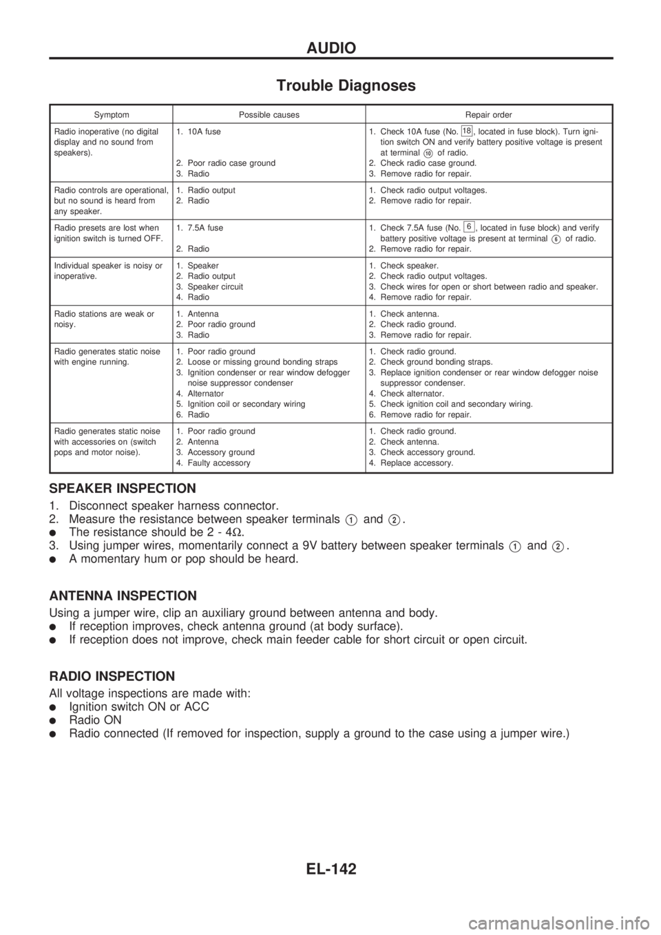
Trouble Diagnoses
Symptom Possible causes Repair order
Radio inoperative (no digital
display and no sound from
speakers).1. 10A fuse
2. Poor radio case ground
3. Radio1. Check 10A fuse (No.
18, located in fuse block). Turn igni-
tion switch ON and verify battery positive voltage is present
at terminal
V10of radio.
2. Check radio case ground.
3. Remove radio for repair.
Radio controls are operational,
but no sound is heard from
any speaker.1. Radio output
2. Radio1. Check radio output voltages.
2. Remove radio for repair.
Radio presets are lost when
ignition switch is turned OFF.1. 7.5A fuse
2. Radio1. Check 7.5A fuse (No.
6, located in fuse block) and verify
battery positive voltage is present at terminal
V6of radio.
2. Remove radio for repair.
Individual speaker is noisy or
inoperative.1. Speaker
2. Radio output
3. Speaker circuit
4. Radio1. Check speaker.
2. Check radio output voltages.
3. Check wires for open or short between radio and speaker.
4. Remove radio for repair.
Radio stations are weak or
noisy.1. Antenna
2. Poor radio ground
3. Radio1. Check antenna.
2. Check radio ground.
3. Remove radio for repair.
Radio generates static noise
with engine running.1. Poor radio ground
2. Loose or missing ground bonding straps
3. Ignition condenser or rear window defogger
noise suppressor condenser
4. Alternator
5. Ignition coil or secondary wiring
6. Radio1. Check radio ground.
2. Check ground bonding straps.
3. Replace ignition condenser or rear window defogger noise
suppressor condenser.
4. Check alternator.
5. Check ignition coil and secondary wiring.
6. Remove radio for repair.
Radio generates static noise
with accessories on (switch
pops and motor noise).1. Poor radio ground
2. Antenna
3. Accessory ground
4. Faulty accessory1. Check radio ground.
2. Check antenna.
3. Check accessory ground.
4. Replace accessory.
SPEAKER INSPECTION
1. Disconnect speaker harness connector.
2. Measure the resistance between speaker terminals
V1andV2.
lThe resistance should be2-4W.
3. Using jumper wires, momentarily connect a 9V battery between speaker terminals
V1andV2.
lA momentary hum or pop should be heard.
ANTENNA INSPECTION
Using a jumper wire, clip an auxiliary ground between antenna and body.
lIf reception improves, check antenna ground (at body surface).
lIf reception does not improve, check main feeder cable for short circuit or open circuit.
RADIO INSPECTION
All voltage inspections are made with:
lIgnition switch ON or ACC
lRadio ON
lRadio connected (If removed for inspection, supply a ground to the case using a jumper wire.)
AUDIO
EL-142
Page 577 of 1659
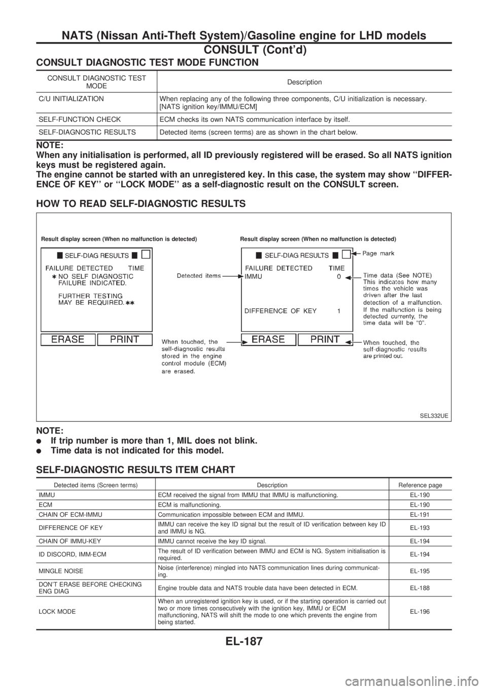
CONSULT DIAGNOSTIC TEST MODE FUNCTION
CONSULT DIAGNOSTIC TEST
MODEDescription
C/U INITIALIZATION When replacing any of the following three components, C/U initialization is necessary.
[NATS ignition key/IMMU/ECM]
SELF-FUNCTION CHECK ECM checks its own NATS communication interface by itself.
SELF-DIAGNOSTIC RESULTS Detected items (screen terms) are as shown in the chart below.
NOTE:
When any initialisation is performed, all ID previously registered will be erased. So all NATS ignition
keys must be registered again.
The engine cannot be started with an unregistered key. In this case, the system may show ``DIFFER-
ENCE OF KEY'' or ``LOCK MODE'' as a self-diagnostic result on the CONSULT screen.
HOW TO READ SELF-DIAGNOSTIC RESULTS
NOTE:
lIf trip number is more than 1, MIL does not blink.
lTime data is not indicated for this model.
SELF-DIAGNOSTIC RESULTS ITEM CHART
Detected items (Screen terms) Description Reference page
IMMU ECM received the signal from IMMU that IMMU is malfunctioning. EL-190
ECM ECM is malfunctioning. EL-190
CHAIN OF ECM-IMMU Communication impossible between ECM and IMMU. EL-191
DIFFERENCE OF KEYIMMU can receive the key ID signal but the result of ID verification between key ID
and IMMU is NG.EL-193
CHAIN OF IMMU-KEY IMMU cannot receive the key ID signal. EL-194
ID DISCORD, IMM-ECMThe result of ID verification between IMMU and ECM is NG. System initialisation is
required.EL-194
MINGLE NOISENoise (interference) mingled into NATS communication lines during communicat-
ing.EL-195
DON'T ERASE BEFORE CHECKING
ENG DIAGEngine trouble data and NATS trouble data have been detected in ECM. EL-188
LOCK MODEWhen an unregistered ignition key is used, or if the starting operation is carried out
two or more times consecutively with the ignition key, IMMU or ECM
malfunctioning, NATS will shift the mode to one which prevents the engine from
being started.EL-196
SEL332UE
.Result display screen (When no malfunction is detected).Result display screen (When no malfunction is detected)
NATS (Nissan Anti-Theft System)/Gasoline engine for LHD models
CONSULT (Cont'd)
EL-187
Page 578 of 1659
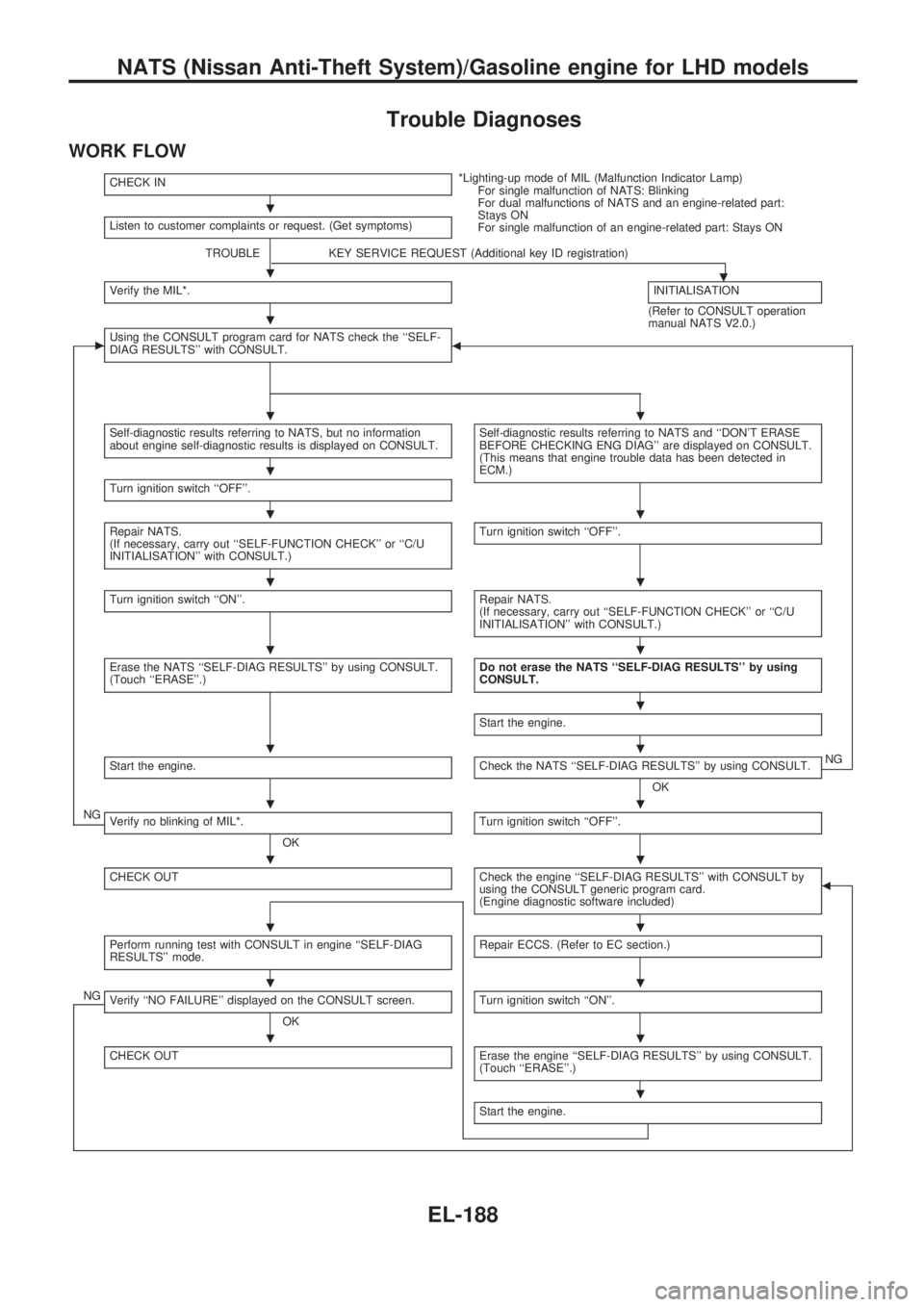
Trouble Diagnoses
WORK FLOW
CHECK IN*Lighting-up mode of MIL (Malfunction Indicator Lamp)
For single malfunction of NATS: Blinking
For dual malfunctions of NATS and an engine-related part:
Stays ON
For single malfunction of an engine-related part: Stays ON Listen to customer complaints or request. (Get symptoms)
TROUBLE KEY SERVICE REQUEST (Additional key ID registration)
.Verify the MIL*.INITIALISATION
(Refer to CONSULT operation
manual NATS V2.0.)
cUsing the CONSULT program card for NATS check the ``SELF-
DIAG RESULTS'' with CONSULT.b
Self-diagnostic results referring to NATS, but no information
about engine self-diagnostic results is displayed on CONSULT.Self-diagnostic results referring to NATS and ``DON'T ERASE
BEFORE CHECKING ENG DIAG'' are displayed on CONSULT.
(This means that engine trouble data has been detected in
ECM.)
Turn ignition switch ``OFF''.
Repair NATS.
(If necessary, carry out ``SELF-FUNCTION CHECK'' or ``C/U
INITIALISATION'' with CONSULT.)Turn ignition switch ``OFF''.
Turn ignition switch ``ON''.Repair NATS.
(If necessary, carry out ``SELF-FUNCTION CHECK'' or ``C/U
INITIALISATION'' with CONSULT.)
Erase the NATS ``SELF-DIAG RESULTS'' by using CONSULT.
(Touch ``ERASE''.)Do not erase the NATS ``SELF-DIAG RESULTS'' by using
CONSULT.
Start the engine.
Start the engine.Check the NATS ``SELF-DIAG RESULTS'' by using CONSULT.
OKNG
NGVerify no blinking of MIL*.
OKTurn ignition switch ``OFF''.
CHECK OUTCheck the engine ``SELF-DIAG RESULTS'' with CONSULT by
using the CONSULT generic program card.
(Engine diagnostic software included)b
Perform running test with CONSULT in engine ``SELF-DIAG
RESULTS'' mode.Repair ECCS. (Refer to EC section.)
NGVerify ``NO FAILURE'' displayed on the CONSULT screen.
OKTurn ignition switch ``ON''.
CHECK OUTErase the engine ``SELF-DIAG RESULTS'' by using CONSULT.
(Touch ``ERASE''.)
Start the engine.
.
.
.
..
.
..
..
..
.
..
..
..
..
..
..
.
NATS (Nissan Anti-Theft System)/Gasoline engine for LHD models
EL-188
Page 579 of 1659
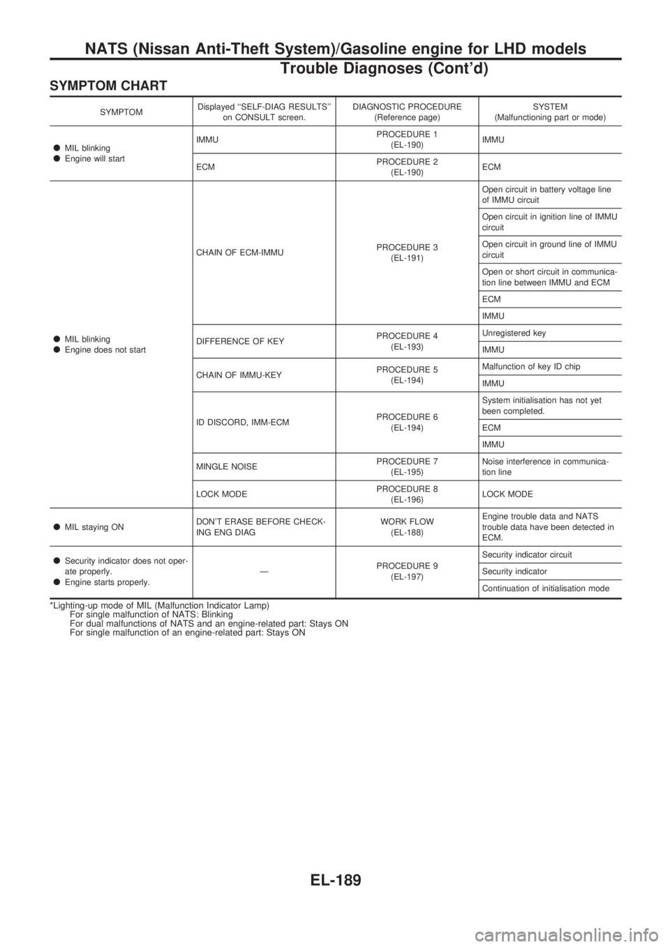
SYMPTOM CHART
SYMPTOMDisplayed ``SELF-DIAG RESULTS''
on CONSULT screen.DIAGNOSTIC PROCEDURE
(Reference page)SYSTEM
(Malfunctioning part or mode)
lMIL blinkinglEngine will startIMMUPROCEDURE 1
(EL-190)IMMU
ECMPROCEDURE 2
(EL-190)ECM
lMIL blinkinglEngine does not startCHAIN OF ECM-IMMUPROCEDURE 3
(EL-191)Open circuit in battery voltage line
of IMMU circuit
Open circuit in ignition line of IMMU
circuit
Open circuit in ground line of IMMU
circuit
Open or short circuit in communica-
tion line between IMMU and ECM
ECM
IMMU
DIFFERENCE OF KEYPROCEDURE 4
(EL-193)Unregistered key
IMMU
CHAIN OF IMMU-KEYPROCEDURE 5
(EL-194)Malfunction of key ID chip
IMMU
ID DISCORD, IMM-ECMPROCEDURE 6
(EL-194)System initialisation has not yet
been completed.
ECM
IMMU
MINGLE NOISEPROCEDURE 7
(EL-195)Noise interference in communica-
tion line
LOCK MODEPROCEDURE 8
(EL-196)LOCK MODE
lMIL staying ONDON'T ERASE BEFORE CHECK-
ING ENG DIAGWORK FLOW
(EL-188)Engine trouble data and NATS
trouble data have been detected in
ECM.
lSecurity indicator does not oper-
ate properly.
lEngine starts properly.ÐPROCEDURE 9
(EL-197)Security indicator circuit
Security indicator
Continuation of initialisation mode
*Lighting-up mode of MIL (Malfunction Indicator Lamp)
For single malfunction of NATS: Blinking
For dual malfunctions of NATS and an engine-related part: Stays ON
For single malfunction of an engine-related part: Stays ON
NATS (Nissan Anti-Theft System)/Gasoline engine for LHD models
Trouble Diagnoses (Cont'd)
EL-189