Page 328 of 1659
CAUTION:
lDisassembly and assembly of the injection pumps should be done only in service shops autho-
rized by NISSAN or by the pump manufacturer.
lThe pump tester is required for servicing the pump.
lBefore removing fuel injection pump from vehicle, check closely to make sure that it is definitely
malfunctioning.
For TD25 engine models with Nissan Anti-Theft System (NATS)
lFor inspection of coded solenoid unit (CSOLU), refer to NATS (Diesel) in EL section.
lWhen replacing injection pump assembly along with CSOLU, perform NATS initialisation with
CONSULT.
For initialisation procedure, refer to NATS (Diesel) in EL section.
Fuel System
SEF378RA
INJECTION SYSTEMTD
EC-176
Page 334 of 1659
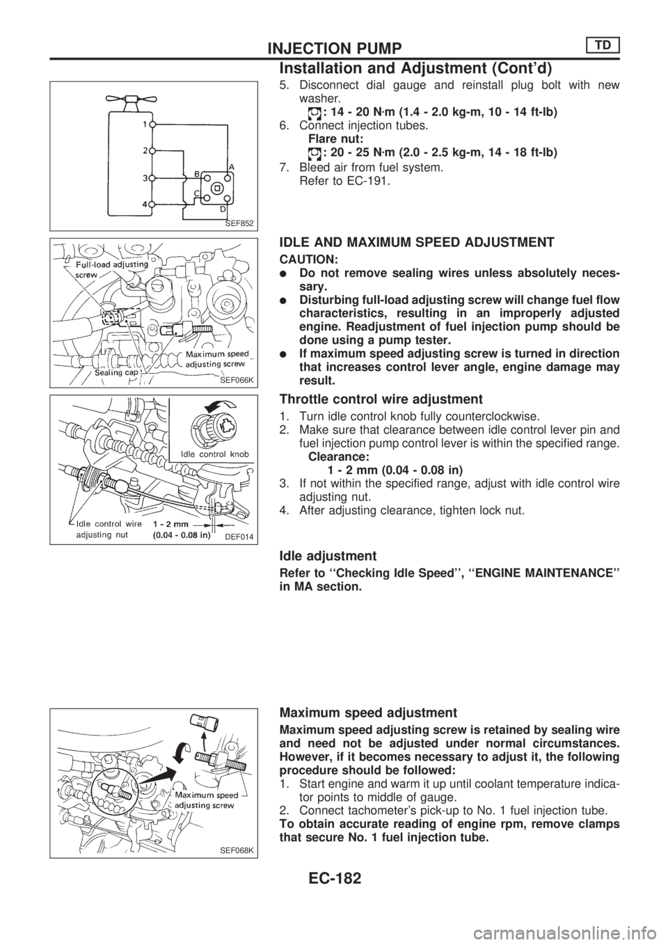
5. Disconnect dial gauge and reinstall plug bolt with new
washer.
:14-20Nzm (1.4 - 2.0 kg-m, 10 - 14 ft-lb)
6. Connect injection tubes.
Flare nut:
:20-25Nzm (2.0 - 2.5 kg-m, 14 - 18 ft-lb)
7. Bleed air from fuel system.
Refer to EC-191.
IDLE AND MAXIMUM SPEED ADJUSTMENT
CAUTION:
lDo not remove sealing wires unless absolutely neces-
sary.
lDisturbing full-load adjusting screw will change fuel flow
characteristics, resulting in an improperly adjusted
engine. Readjustment of fuel injection pump should be
done using a pump tester.
lIf maximum speed adjusting screw is turned in direction
that increases control lever angle, engine damage may
result.
Throttle control wire adjustment
1. Turn idle control knob fully counterclockwise.
2. Make sure that clearance between idle control lever pin and
fuel injection pump control lever is within the specified range.
Clearance:
1-2mm(0.04 - 0.08 in)
3. If not within the specified range, adjust with idle control wire
adjusting nut.
4. After adjusting clearance, tighten lock nut.
Idle adjustment
Refer to ``Checking Idle Speed'', ``ENGINE MAINTENANCE''
in MA section.
Maximum speed adjustment
Maximum speed adjusting screw is retained by sealing wire
and need not be adjusted under normal circumstances.
However, if it becomes necessary to adjust it, the following
procedure should be followed:
1. Start engine and warm it up until coolant temperature indica-
tor points to middle of gauge.
2. Connect tachometer's pick-up to No. 1 fuel injection tube.
To obtain accurate reading of engine rpm, remove clamps
that secure No. 1 fuel injection tube.
SEF852
SEF066K
DEF014
SEF068K
INJECTION PUMPTD
Installation and Adjustment (Cont'd)
EC-182
Page 343 of 1659
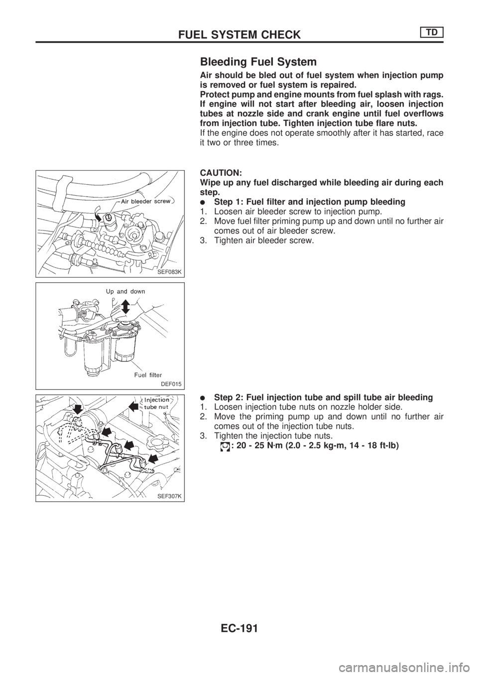
Bleeding Fuel System
Air should be bled out of fuel system when injection pump
is removed or fuel system is repaired.
Protect pump and engine mounts from fuel splash with rags.
If engine will not start after bleeding air, loosen injection
tubes at nozzle side and crank engine until fuel overflows
from injection tube. Tighten injection tube flare nuts.
If the engine does not operate smoothly after it has started, race
it two or three times.
CAUTION:
Wipe up any fuel discharged while bleeding air during each
step.
lStep 1: Fuel filter and injection pump bleeding
1. Loosen air bleeder screw to injection pump.
2. Move fuel filter priming pump up and down until no further air
comes out of air bleeder screw.
3. Tighten air bleeder screw.
lStep 2: Fuel injection tube and spill tube air bleeding
1. Loosen injection tube nuts on nozzle holder side.
2. Move the priming pump up and down until no further air
comes out of the injection tube nuts.
3. Tighten the injection tube nuts.
:20-25Nzm (2.0 - 2.5 kg-m, 14 - 18 ft-lb)
SEF083K
DEF015
SEF307K
FUEL SYSTEM CHECKTD
EC-191
Page 355 of 1659
Glow Control Unit Circuit Inspection (For
Cold Areas)
Roll up the floor sheet. Check the glow control unit.
POWER SUPPLY CIRCUIT
Turn ignition switch ON and check voltage between terminalV1
orV11and body ground.
Voltage: approx. 12V
GROUND CIRCUIT
Check continuity between terminalV12,V13,V17orV18and body
ground.
Continuity should exist.
VEHICLE SPEED SENSOR CIRCUIT
While running vehicle or lifting rear wheels in 2WD position,
check that voltage between terminal
V10and body ground fluctu-
ates.
Voltage: approx. 5V
ENGINE COOLANT TEMPERATURE SENSOR
CIRCUIT
Check continuity between terminalsV21andV19orV20.
Measure resistance to temperature approximately as shown in
``ENGINE COOLANT TEMPERATURE SENSOR'', ``Component
Inspection'', EC-209.
DEF022-A
.
DEC044
DEC018
DEC019
DEC020
QUICK-GLOW SYSTEMTD
EC-203
Page 358 of 1659
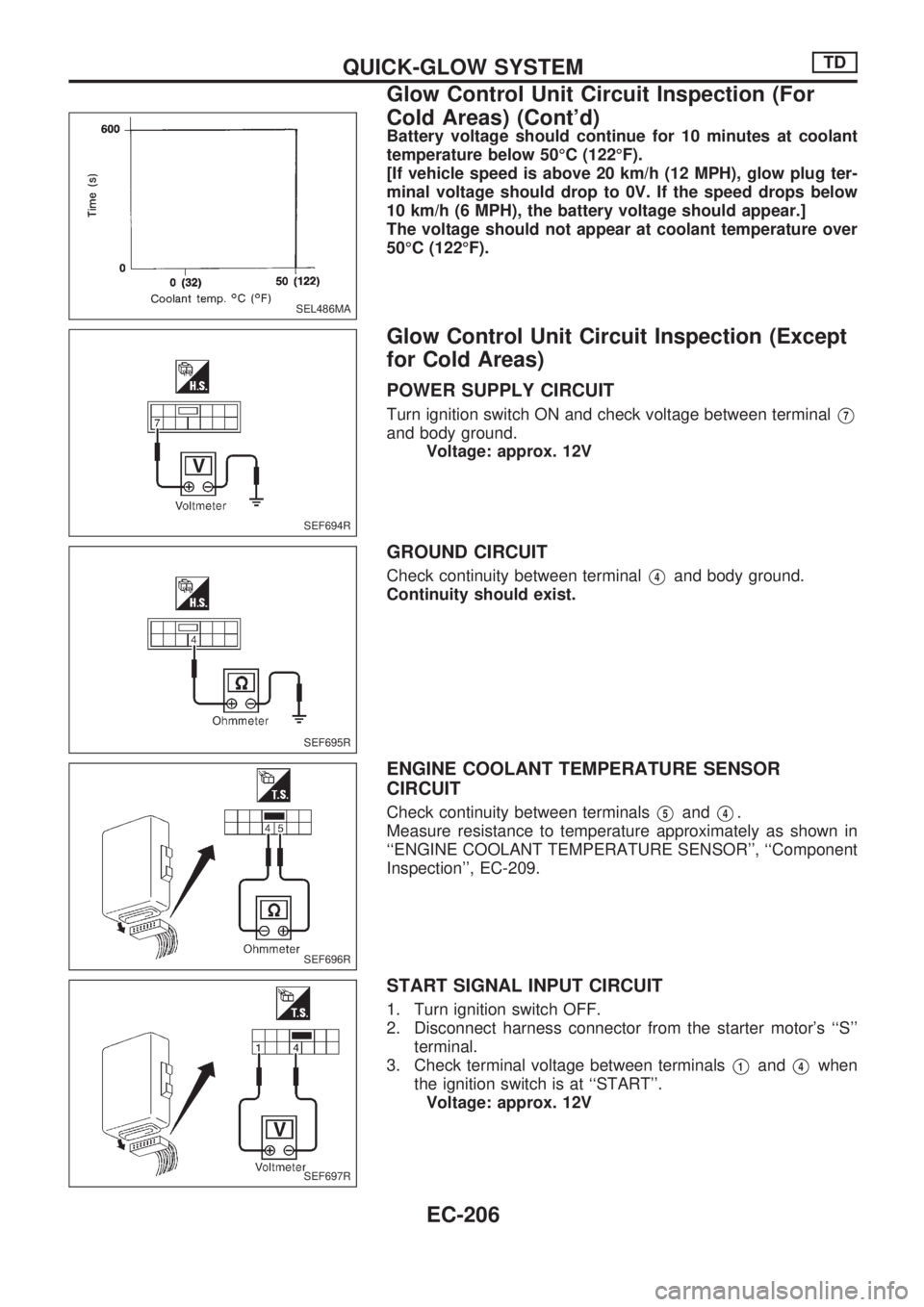
Battery voltage should continue for 10 minutes at coolant
temperature below 50ÉC (122ÉF).
[If vehicle speed is above 20 km/h (12 MPH), glow plug ter-
minal voltage should drop to 0V. If the speed drops below
10 km/h (6 MPH), the battery voltage should appear.]
The voltage should not appear at coolant temperature over
50ÉC (122ÉF).
Glow Control Unit Circuit Inspection (Except
for Cold Areas)
POWER SUPPLY CIRCUIT
Turn ignition switch ON and check voltage between terminalV7
and body ground.
Voltage: approx. 12V
GROUND CIRCUIT
Check continuity between terminalV4and body ground.
Continuity should exist.
ENGINE COOLANT TEMPERATURE SENSOR
CIRCUIT
Check continuity between terminalsV5andV4.
Measure resistance to temperature approximately as shown in
``ENGINE COOLANT TEMPERATURE SENSOR'', ``Component
Inspection'', EC-209.
START SIGNAL INPUT CIRCUIT
1. Turn ignition switch OFF.
2. Disconnect harness connector from the starter motor's ``S''
terminal.
3. Check terminal voltage between terminals
V1andV4when
the ignition switch is at ``START''.
Voltage: approx. 12V
SEL486MA
SEF694R
SEF695R
SEF696R
SEF697R
QUICK-GLOW SYSTEMTD
Glow Control Unit Circuit Inspection (For
Cold Areas) (Cont'd)
EC-206
Page 360 of 1659
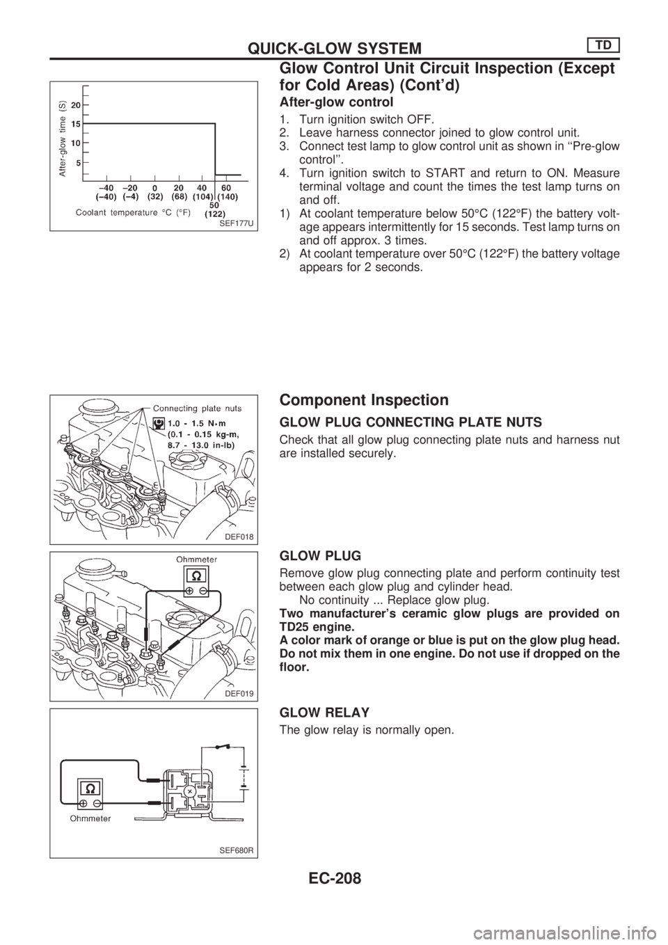
After-glow control
1. Turn ignition switch OFF.
2. Leave harness connector joined to glow control unit.
3. Connect test lamp to glow control unit as shown in ``Pre-glow
control''.
4. Turn ignition switch to START and return to ON. Measure
terminal voltage and count the times the test lamp turns on
and off.
1) At coolant temperature below 50ÉC (122ÉF) the battery volt-
age appears intermittently for 15 seconds. Test lamp turns on
and off approx. 3 times.
2) At coolant temperature over 50ÉC (122ÉF) the battery voltage
appears for 2 seconds.
Component Inspection
GLOW PLUG CONNECTING PLATE NUTS
Check that all glow plug connecting plate nuts and harness nut
are installed securely.
GLOW PLUG
Remove glow plug connecting plate and perform continuity test
between each glow plug and cylinder head.
No continuity ... Replace glow plug.
Two manufacturer's ceramic glow plugs are provided on
TD25 engine.
A color mark of orange or blue is put on the glow plug head.
Do not mix them in one engine. Do not use if dropped on the
floor.
GLOW RELAY
The glow relay is normally open.
SEF177U
DEF018
DEF019
SEF680R
QUICK-GLOW SYSTEMTD
Glow Control Unit Circuit Inspection (Except
for Cold Areas) (Cont'd)
EC-208
Page 369 of 1659
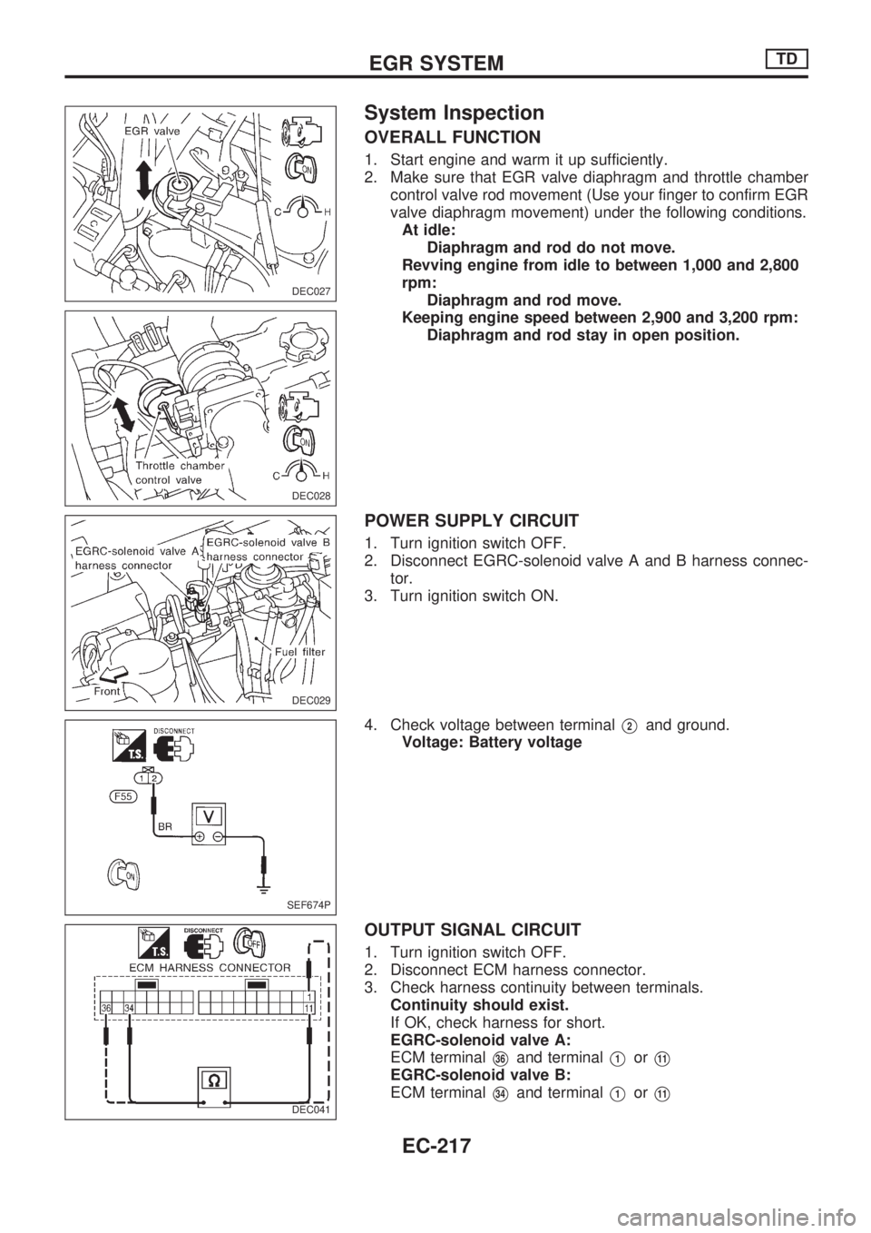
System Inspection
OVERALL FUNCTION
1. Start engine and warm it up sufficiently.
2. Make sure that EGR valve diaphragm and throttle chamber
control valve rod movement (Use your finger to confirm EGR
valve diaphragm movement) under the following conditions.
At idle:
Diaphragm and rod do not move.
Revving engine from idle to between 1,000 and 2,800
rpm:
Diaphragm and rod move.
Keeping engine speed between 2,900 and 3,200 rpm:
Diaphragm and rod stay in open position.
POWER SUPPLY CIRCUIT
1. Turn ignition switch OFF.
2. Disconnect EGRC-solenoid valve A and B harness connec-
tor.
3. Turn ignition switch ON.
4. Check voltage between terminal
V2and ground.
Voltage: Battery voltage
OUTPUT SIGNAL CIRCUIT
1. Turn ignition switch OFF.
2. Disconnect ECM harness connector.
3. Check harness continuity between terminals.
Continuity should exist.
If OK, check harness for short.
EGRC-solenoid valve A:
ECM terminal
V36and terminalV1orV11
EGRC-solenoid valve B:
ECM terminal
V34and terminalV1orV11
DEC027
DEC028
DEC029
SEF674P
DEC041
EGR SYSTEMTD
EC-217
Page 370 of 1659
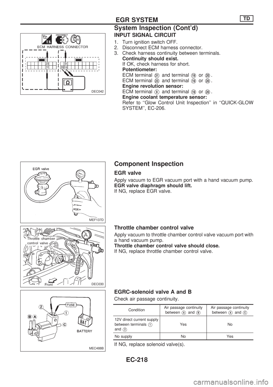
INPUT SIGNAL CIRCUIT
1. Turn ignition switch OFF.
2. Disconnect ECM harness connector.
3. Check harness continuity between terminals.
Continuity should exist.
If OK, check harness for short.
Potentiometer:
ECM terminal
V31and terminalV19orV20.
ECM terminal
V23and terminalV19orV20.
Engine revolution sensor:
ECM terminal
V9and terminalV19orV20.
Engine coolant temperature sensor:
Refer to ``Glow Control Unit Inspection'' in ``QUICK-GLOW
SYSTEM'', EC-206.
Component Inspection
EGR valve
Apply vacuum to EGR vacuum port with a hand vacuum pump.
EGR valve diaphragm should lift.
If NG, replace EGR valve.
Throttle chamber control valve
Apply vacuum to throttle chamber control valve vacuum port with
a hand vacuum pump.
Throttle chamber control valve should close.
If NG, replace throttle chamber control valve.
EGRC-solenoid valve A and B
Check air passage continuity.
ConditionAir passage continuity
betweenVAandVB
Air passage continuity
between
VAandVC
12V direct current supply
between terminals
V1
andV2
Yes No
No supply No Yes
If NG, replace solenoid valve(s).
DEC042
MEF137D
DEC030
MEC488B
EGR SYSTEMTD
System Inspection (Cont'd)
EC-218