1998 NISSAN PICK-UP check engine
[x] Cancel search: check enginePage 235 of 1659
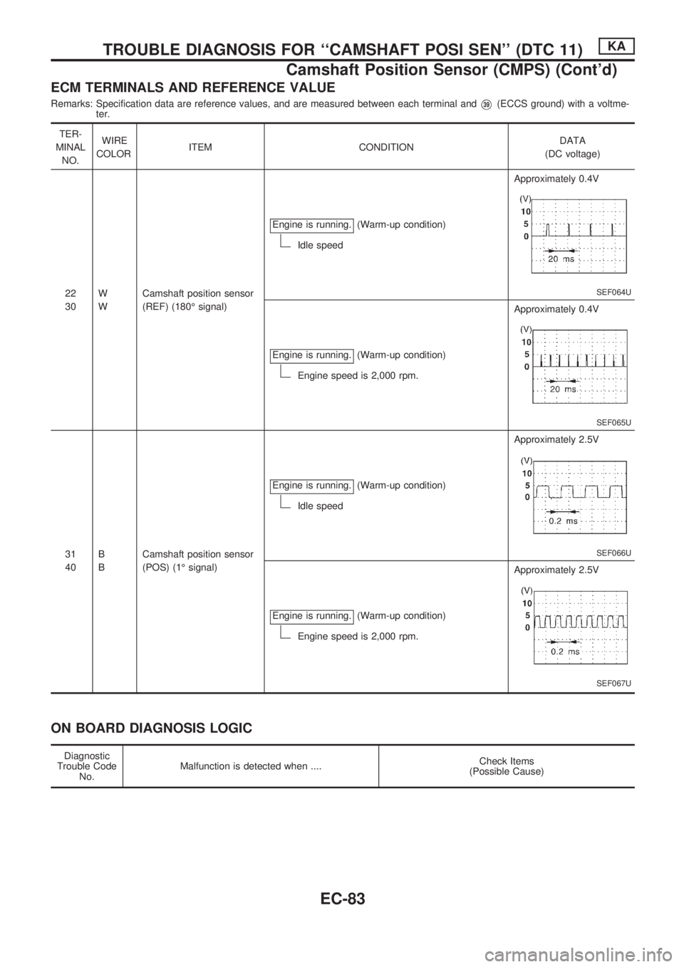
ECM TERMINALS AND REFERENCE VALUE
Remarks: Specification data are reference values, and are measured between each terminal andV39(ECCS ground) with a voltme-
ter.
TER-
MINAL
NO.WIRE
COLORITEM CONDITIONDATA
(DC voltage)
22
30W
WCamshaft position sensor
(REF) (180É signal)Engine is running.
(Warm-up condition)
Idle speedApproximately 0.4V
SEF064U
Engine is running.(Warm-up condition)
Engine speed is 2,000 rpm.Approximately 0.4V
SEF065U
31
40B
BCamshaft position sensor
(POS) (1É signal)Engine is running.
(Warm-up condition)
Idle speedApproximately 2.5V
SEF066U
Engine is running.(Warm-up condition)
Engine speed is 2,000 rpm.Approximately 2.5V
SEF067U
ON BOARD DIAGNOSIS LOGIC
Diagnostic
Trouble Code
No.Malfunction is detected when ....Check Items
(Possible Cause)
TROUBLE DIAGNOSIS FOR ``CAMSHAFT POSI SEN'' (DTC 11)KA
Camshaft Position Sensor (CMPS) (Cont'd)
EC-83
Page 239 of 1659
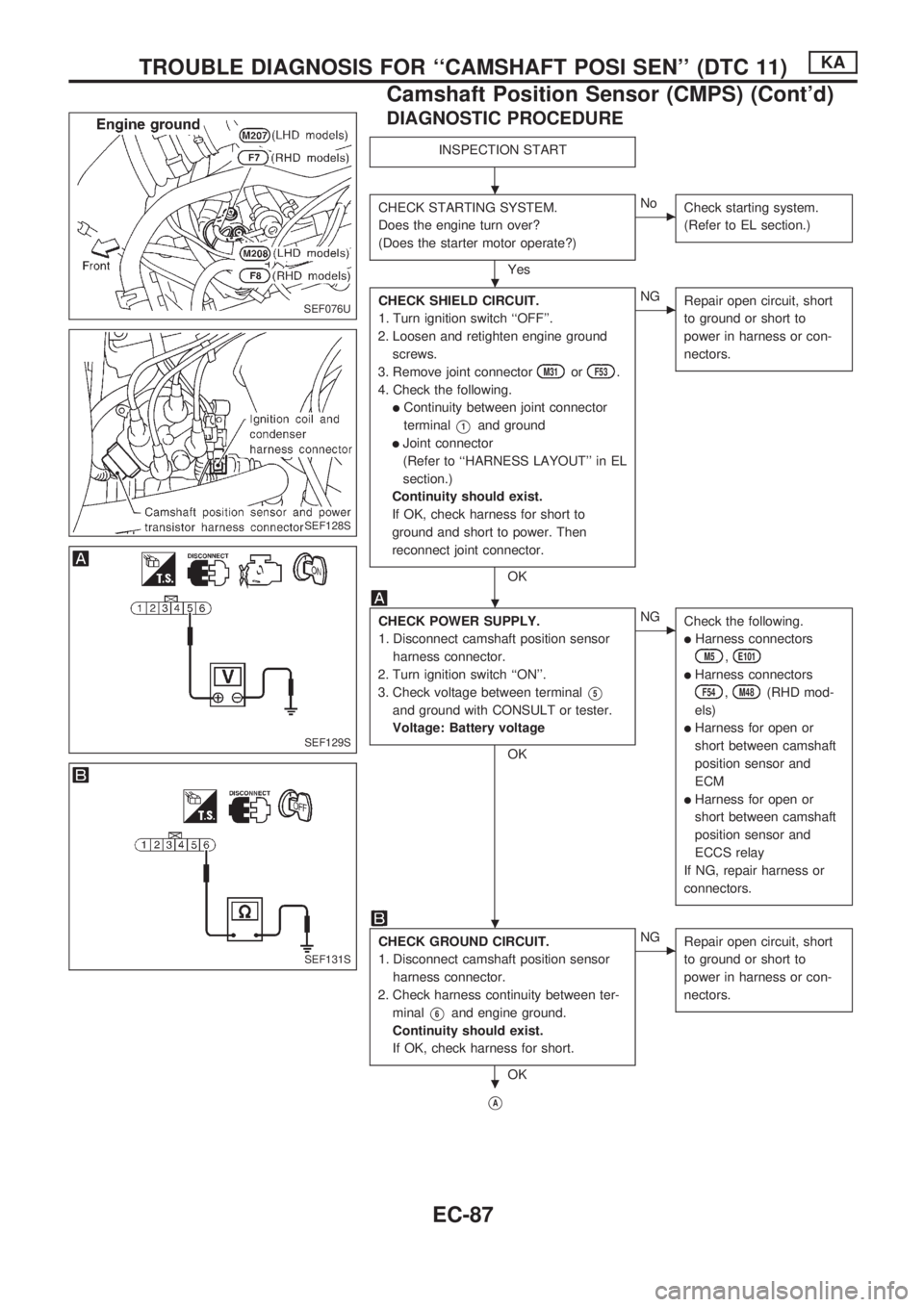
DIAGNOSTIC PROCEDURE
INSPECTION START
CHECK STARTING SYSTEM.
Does the engine turn over?
(Does the starter motor operate?)
Yes
cNo
Check starting system.
(Refer to EL section.)
CHECK SHIELD CIRCUIT.
1. Turn ignition switch ``OFF''.
2. Loosen and retighten engine ground
screws.
3. Remove joint connector
M31orF53.
4. Check the following.
lContinuity between joint connector
terminal
V1and ground
lJoint connector
(Refer to ``HARNESS LAYOUT'' in EL
section.)
Continuity should exist.
If OK, check harness for short to
ground and short to power. Then
reconnect joint connector.
OK
cNG
Repair open circuit, short
to ground or short to
power in harness or con-
nectors.
CHECK POWER SUPPLY.
1. Disconnect camshaft position sensor
harness connector.
2. Turn ignition switch ``ON''.
3. Check voltage between terminal
V5
and ground with CONSULT or tester.
Voltage: Battery voltage
OK
cNG
Check the following.
lHarness connectors
M5,E101
lHarness connectors
F54,M48(RHD mod-
els)
lHarness for open or
short between camshaft
position sensor and
ECM
lHarness for open or
short between camshaft
position sensor and
ECCS relay
If NG, repair harness or
connectors.
CHECK GROUND CIRCUIT.
1. Disconnect camshaft position sensor
harness connector.
2. Check harness continuity between ter-
minal
V6and engine ground.
Continuity should exist.
If OK, check harness for short.
OK
cNG
Repair open circuit, short
to ground or short to
power in harness or con-
nectors.
VA
SEF076U
SEF128S
SEF129S
SEF131S
.
.
.
.
.
TROUBLE DIAGNOSIS FOR ``CAMSHAFT POSI SEN'' (DTC 11)KA
Camshaft Position Sensor (CMPS) (Cont'd)
EC-87
Page 240 of 1659
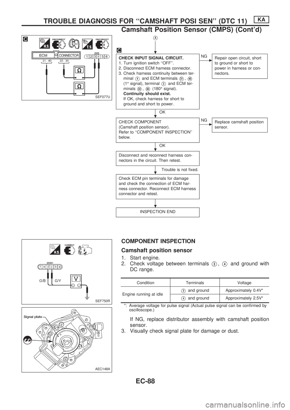
VA
CHECK INPUT SIGNAL CIRCUIT.
1. Turn ignition switch ``OFF''.
2. Disconnect ECM harness connector.
3. Check harness continuity between ter-
minal
V4and ECM terminalsV31,V40
(1É signal), terminalV3and ECM ter-
minals
V22,V30(180É signal).
Continuity should exist.
If OK, check harness for short to
ground and short to power.
OK
cNG
Repair open circuit, short
to ground or short to
power in harness or con-
nectors.
CHECK COMPONENT
(Camshaft position sensor).
Refer to ``COMPONENT INSPECTION''
below.
OK
cNG
Replace camshaft position
sensor.
Disconnect and reconnect harness con-
nectors in the circuit. Then retest.
Trouble is not fixed.
Check ECM pin terminals for damage
and check the connection of ECM har-
ness connector. Reconnect ECM harness
connector and retest.
INSPECTION END
COMPONENT INSPECTION
Camshaft position sensor
1. Start engine.
2. Check voltage between terminals
V3,V4and ground with
DC range.
Condition Terminals Voltage
Engine running at idle
V3and ground Approximately 0.4V*
V4and ground Approximately 2.5V*
*: Average voltage for pulse signal (Actual pulse signal can be confirmed by
oscilloscope.)
If NG, replace distributor assembly with camshaft position
sensor.
3. Visually check signal plate for damage or dust.
SEF077U
SEF750R
AEC148A
.
.
.
.
.
TROUBLE DIAGNOSIS FOR ``CAMSHAFT POSI SEN'' (DTC 11)KA
Camshaft Position Sensor (CMPS) (Cont'd)
EC-88
Page 241 of 1659
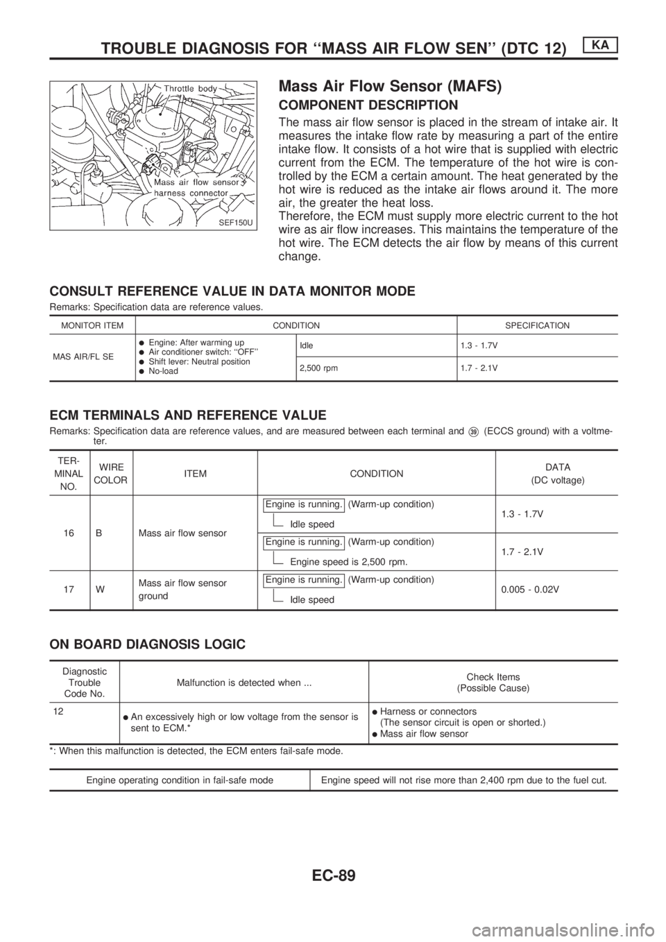
Mass Air Flow Sensor (MAFS)
COMPONENT DESCRIPTION
The mass air flow sensor is placed in the stream of intake air. It
measures the intake flow rate by measuring a part of the entire
intake flow. It consists of a hot wire that is supplied with electric
current from the ECM. The temperature of the hot wire is con-
trolled by the ECM a certain amount. The heat generated by the
hot wire is reduced as the intake air flows around it. The more
air, the greater the heat loss.
Therefore, the ECM must supply more electric current to the hot
wire as air flow increases. This maintains the temperature of the
hot wire. The ECM detects the air flow by means of this current
change.
CONSULT REFERENCE VALUE IN DATA MONITOR MODE
Remarks: Specification data are reference values.
MONITOR ITEM CONDITION SPECIFICATION
MAS AIR/FL SE
lEngine: After warming uplAir conditioner switch: ``OFF''lShift lever: Neutral positionlNo-loadIdle 1.3 - 1.7V
2,500 rpm 1.7 - 2.1V
ECM TERMINALS AND REFERENCE VALUE
Remarks: Specification data are reference values, and are measured between each terminal andV39(ECCS ground) with a voltme-
ter.
TER-
MINAL
NO.WIRE
COLORITEM CONDITIONDATA
(DC voltage)
16 B Mass air flow sensorEngine is running.
(Warm-up condition)
Idle speed1.3 - 1.7V
Engine is running.
(Warm-up condition)
Engine speed is 2,500 rpm.1.7 - 2.1V
17 WMass air flow sensor
groundEngine is running.
(Warm-up condition)
Idle speed0.005 - 0.02V
ON BOARD DIAGNOSIS LOGIC
Diagnostic
Trouble
Code No.Malfunction is detected when ...Check Items
(Possible Cause)
12
lAn excessively high or low voltage from the sensor is
sent to ECM.*lHarness or connectors
(The sensor circuit is open or shorted.)
lMass air flow sensor
*: When this malfunction is detected, the ECM enters fail-safe mode.
Engine operating condition in fail-safe mode Engine speed will not rise more than 2,400 rpm due to the fuel cut.
SEF150U
TROUBLE DIAGNOSIS FOR ``MASS AIR FLOW SEN'' (DTC 12)KA
EC-89
Page 245 of 1659
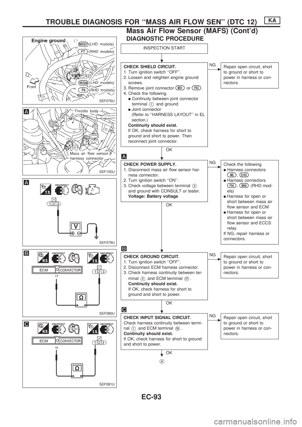
DIAGNOSTIC PROCEDURE
INSPECTION START
CHECK SHIELD CIRCUIT.
1. Turn ignition switch ``OFF''.
2. Loosen and retighten engine ground
screws.
3. Remove joint connector
M31orF53.
4. Check the following.
lContinuity between joint connector
terminal
V1and ground
lJoint connector
(Refer to ``HARNESS LAYOUT'' in EL
section.)
Continuity should exist.
If OK, check harness for short to
ground and short to power. Then
reconnect joint connector.
OK
cNG
Repair open circuit, short
to ground or short to
power in harness or con-
nectors.
CHECK POWER SUPPLY.
1. Disconnect mass air flow sensor har-
ness connector.
2. Turn ignition switch ``ON''.
3. Check voltage between terminal
V3
and ground with CONSULT or tester.
Voltage: Battery voltage
OK
cNG
Check the following.
lHarness connectorsM5,E101
lHarness connectorsF54,M48(RHD mod-
els)
lHarness for open or
short between mass air
flow sensor and ECM
lHarness for open or
short between mass air
flow sensor and ECCS
relay
If NG, repair harness or
connectors.
CHECK GROUND CIRCUIT.
1. Turn ignition switch ``OFF''.
2. Disconnect ECM harness connector.
3. Check harness continuity between ter-
minal
V2and ECM terminalV17.
Continuity should exist.
If OK, check harness for short to
ground and short to power.
OK
cNG
Repair open circuit, short
to ground or short to
power in harness or con-
nectors.
CHECK INPUT SIGNAL CIRCUIT.
Check harness continuity between termi-
nal
V1and ECM terminalV16.
Continuity should exist.
If OK, check harness for short to ground
and short to power.
OK
cNG
Repair open circuit, short
to ground or short to
power in harness or con-
nectors.
VA
SEF076U
SEF150U
SEF079U
SEF080U
SEF081U
.
.
.
.
.
TROUBLE DIAGNOSIS FOR ``MASS AIR FLOW SEN'' (DTC 12)KA
Mass Air Flow Sensor (MAFS) (Cont'd)
EC-93
Page 246 of 1659
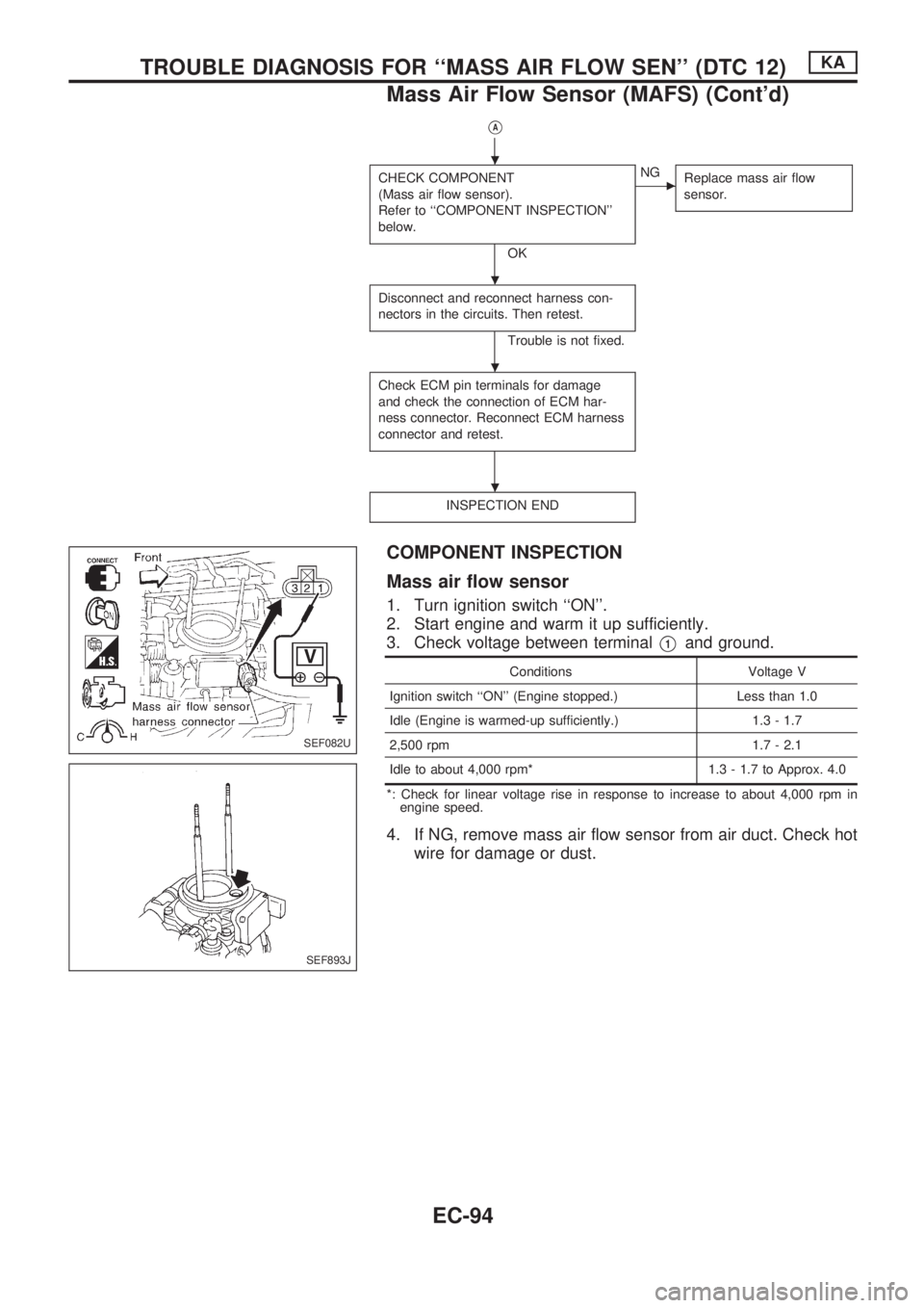
VA
CHECK COMPONENT
(Mass air flow sensor).
Refer to ``COMPONENT INSPECTION''
below.
OK
cNG
Replace mass air flow
sensor.
Disconnect and reconnect harness con-
nectors in the circuits. Then retest.
Trouble is not fixed.
Check ECM pin terminals for damage
and check the connection of ECM har-
ness connector. Reconnect ECM harness
connector and retest.
INSPECTION END
COMPONENT INSPECTION
Mass air flow sensor
1. Turn ignition switch ``ON''.
2. Start engine and warm it up sufficiently.
3. Check voltage between terminal
V1and ground.
Conditions Voltage V
Ignition switch ``ON'' (Engine stopped.) Less than 1.0
Idle (Engine is warmed-up sufficiently.) 1.3 - 1.7
2,500 rpm 1.7 - 2.1
Idle to about 4,000 rpm* 1.3 - 1.7 to Approx. 4.0
*: Check for linear voltage rise in response to increase to about 4,000 rpm in
engine speed.
4. If NG, remove mass air flow sensor from air duct. Check hot
wire for damage or dust.
SEF082U
SEF893J
.
.
.
.
TROUBLE DIAGNOSIS FOR ``MASS AIR FLOW SEN'' (DTC 12)KA
Mass Air Flow Sensor (MAFS) (Cont'd)
EC-94
Page 247 of 1659
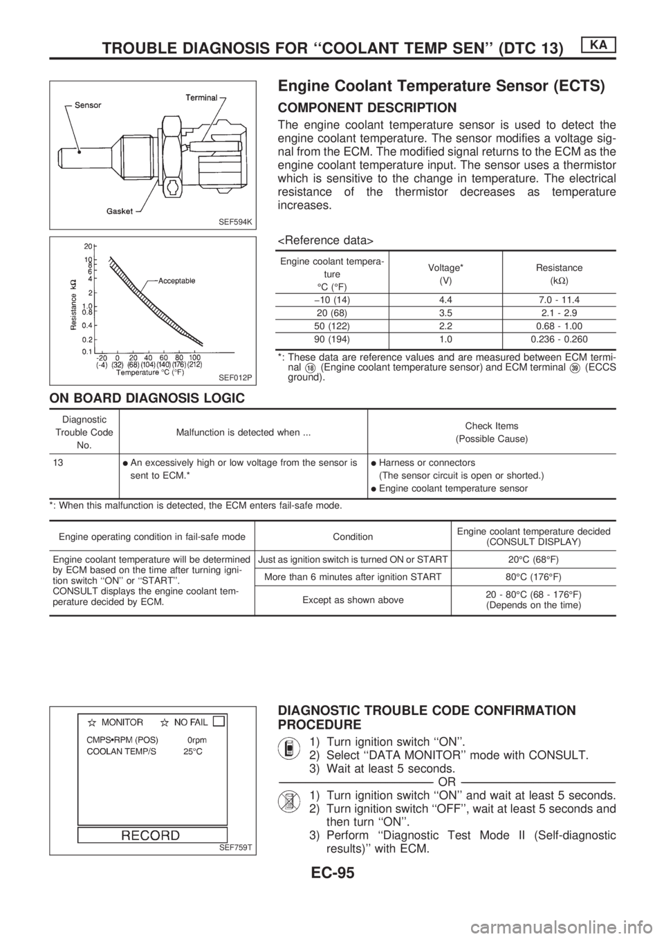
Engine Coolant Temperature Sensor (ECTS)
COMPONENT DESCRIPTION
The engine coolant temperature sensor is used to detect the
engine coolant temperature. The sensor modifies a voltage sig-
nal from the ECM. The modified signal returns to the ECM as the
engine coolant temperature input. The sensor uses a thermistor
which is sensitive to the change in temperature. The electrical
resistance of the thermistor decreases as temperature
increases.
Engine coolant tempera-
ture
ÉC (ÉF)Voltage*
(V)Resistance
(kW)
þ10 (14) 4.4 7.0 - 11.4
20 (68) 3.5 2.1 - 2.9
50 (122) 2.2 0.68 - 1.00
90 (194) 1.0 0.236 - 0.260
*: These data are reference values and are measured between ECM termi-
nal
V18(Engine coolant temperature sensor) and ECM terminalV39(ECCS
ground).
ON BOARD DIAGNOSIS LOGIC
Diagnostic
Trouble Code
No.Malfunction is detected when ...Check Items
(Possible Cause)
13
lAn excessively high or low voltage from the sensor is
sent to ECM.*lHarness or connectors
(The sensor circuit is open or shorted.)
lEngine coolant temperature sensor
*: When this malfunction is detected, the ECM enters fail-safe mode.
Engine operating condition in fail-safe mode ConditionEngine coolant temperature decided
(CONSULT DISPLAY)
Engine coolant temperature will be determined
by ECM based on the time after turning igni-
tion switch ``ON'' or ``START''.
CONSULT displays the engine coolant tem-
perature decided by ECM.Just as ignition switch is turned ON or START 20ÉC (68ÉF)
More than 6 minutes after ignition START 80ÉC (176ÉF)
Except as shown above20 - 80ÉC (68 - 176ÉF)
(Depends on the time)
DIAGNOSTIC TROUBLE CODE CONFIRMATION
PROCEDURE
1) Turn ignition switch ``ON''.
2) Select ``DATA MONITOR'' mode with CONSULT.
3) Wait at least 5 seconds.
-------------------------------------------------------------------------------------------------------------------------------------------------------------------------------------------------------------------------------------------------OR-------------------------------------------------------------------------------------------------------------------------------------------------------------------------------------------------------------------------------------------------
1) Turn ignition switch ``ON'' and wait at least 5 seconds.
2) Turn ignition switch ``OFF'', wait at least 5 seconds and
then turn ``ON''.
3) Perform ``Diagnostic Test Mode II (Self-diagnostic
results)'' with ECM.
SEF594K
SEF012P
SEF759T
TROUBLE DIAGNOSIS FOR ``COOLANT TEMP SEN'' (DTC 13)KA
EC-95
Page 249 of 1659
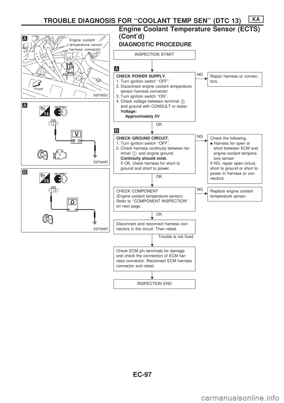
DIAGNOSTIC PROCEDURE
INSPECTION START
CHECK POWER SUPPLY.
1. Turn ignition switch ``OFF''.
2. Disconnect engine coolant temperature
sensor harness connector.
3. Turn ignition switch ``ON''.
4. Check voltage between terminal
V2
and ground with CONSULT or tester.
Voltage:
Approximately 5V
OK
cNG
Repair harness or connec-
tors.
CHECK GROUND CIRCUIT.
1. Turn ignition switch ``OFF''.
2. Check harness continuity between ter-
minal
V1and engine ground.
Continuity should exist.
If OK, check harness for short to
ground and short to power.
OK
cNG
Check the following.
lHarness for open or
short between ECM and
engine coolant tempera-
ture sensor
If NG, repair open circuit,
short to ground or short to
power in harness or con-
nectors.
CHECK COMPONENT
(Engine coolant temperature sensor).
Refer to ``COMPONENT INSPECTION''
on next page.
OK
cNG
Replace engine coolant
temperature sensor.
Disconnect and reconnect harness con-
nectors in the circuit. Then retest.
Trouble is not fixed.
Check ECM pin terminals for damage
and check the connection of ECM har-
ness connector. Reconnect ECM harness
connector and retest.
INSPECTION END
SEF083U
SEF645R
SEF646R
.
.
.
.
.
.
TROUBLE DIAGNOSIS FOR ``COOLANT TEMP SEN'' (DTC 13)KA
Engine Coolant Temperature Sensor (ECTS)
(Cont'd)
EC-97