1998 NISSAN PICK-UP check engine
[x] Cancel search: check enginePage 286 of 1659
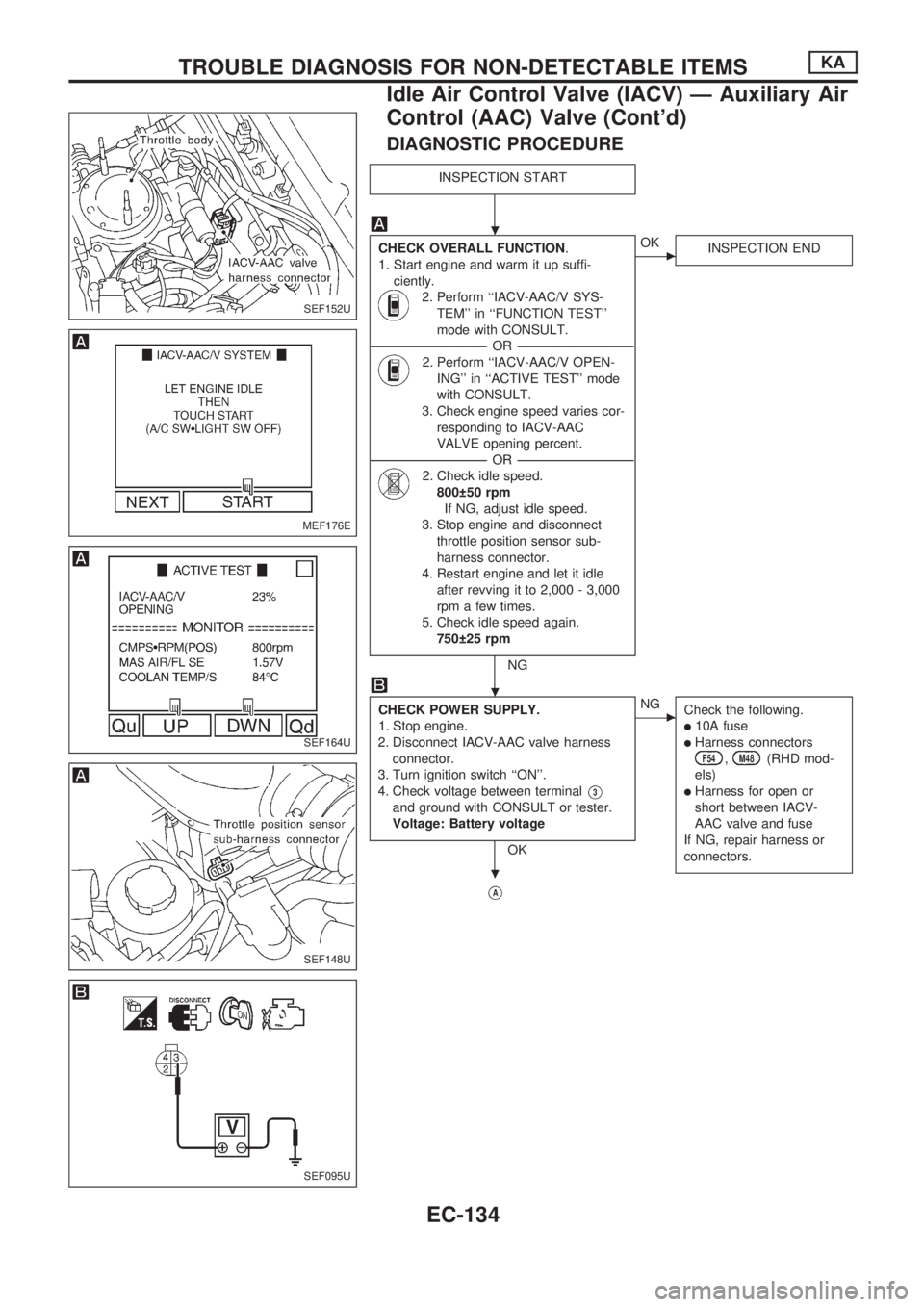
DIAGNOSTIC PROCEDURE
INSPECTION START
CHECK OVERALL FUNCTION.
1. Start engine and warm it up suffi-
ciently.
2. Perform ``IACV-AAC/V SYS-
TEM'' in ``FUNCTION TEST''
mode with CONSULT.
----------------------------------------------------------------------------------------------------------------------------------OR----------------------------------------------------------------------------------------------------------------------------------
2. Perform ``IACV-AAC/V OPEN-
ING'' in ``ACTIVE TEST'' mode
with CONSULT.
3. Check engine speed varies cor-
responding to IACV-AAC
VALVE opening percent.
----------------------------------------------------------------------------------------------------------------------------------OR----------------------------------------------------------------------------------------------------------------------------------
2. Check idle speed.
800 50 rpm
If NG, adjust idle speed.
3. Stop engine and disconnect
throttle position sensor sub-
harness connector.
4. Restart engine and let it idle
after revving it to 2,000 - 3,000
rpm a few times.
5. Check idle speed again.
750 25 rpm
NG
cOK
INSPECTION END
CHECK POWER SUPPLY.
1. Stop engine.
2. Disconnect IACV-AAC valve harness
connector.
3. Turn ignition switch ``ON''.
4. Check voltage between terminal
V3
and ground with CONSULT or tester.
Voltage: Battery voltage
OK
cNG
Check the following.
l10A fuse
lHarness connectorsF54,M48(RHD mod-
els)
lHarness for open or
short between IACV-
AAC valve and fuse
If NG, repair harness or
connectors.
VA
SEF152U
MEF176E
SEF164U
SEF148U
SEF095U
.
.
.
TROUBLE DIAGNOSIS FOR NON-DETECTABLE ITEMSKA
Idle Air Control Valve (IACV) Ð Auxiliary Air
Control (AAC) Valve (Cont'd)
EC-134
Page 294 of 1659
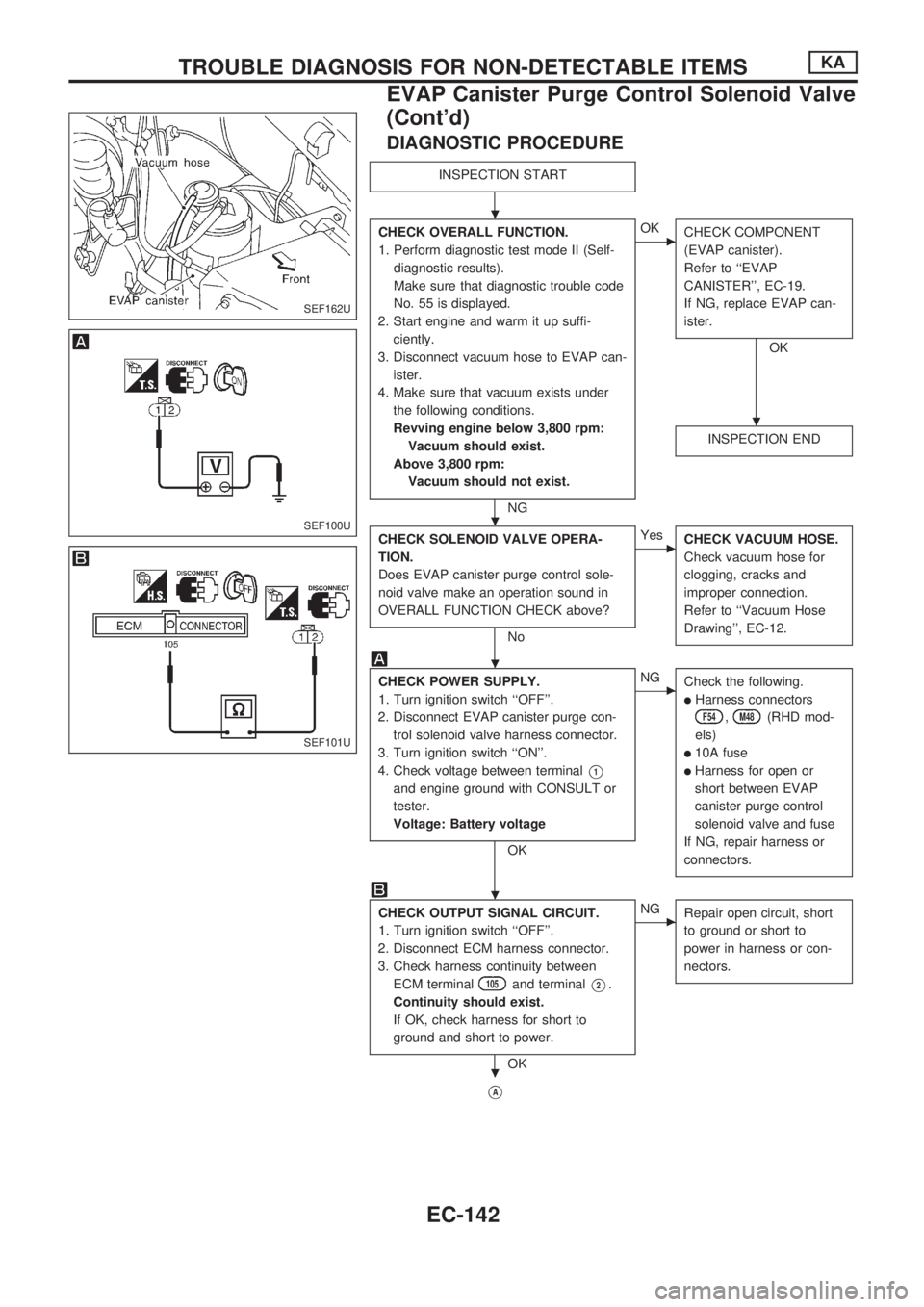
DIAGNOSTIC PROCEDURE
INSPECTION START
CHECK OVERALL FUNCTION.
1. Perform diagnostic test mode II (Self-
diagnostic results).
Make sure that diagnostic trouble code
No. 55 is displayed.
2. Start engine and warm it up suffi-
ciently.
3. Disconnect vacuum hose to EVAP can-
ister.
4. Make sure that vacuum exists under
the following conditions.
Revving engine below 3,800 rpm:
Vacuum should exist.
Above 3,800 rpm:
Vacuum should not exist.
NG
cOK
CHECK COMPONENT
(EVAP canister).
Refer to ``EVAP
CANISTER'', EC-19.
If NG, replace EVAP can-
ister.
OK
INSPECTION END
CHECK SOLENOID VALVE OPERA-
TION.
Does EVAP canister purge control sole-
noid valve make an operation sound in
OVERALL FUNCTION CHECK above?
No
cYes
CHECK VACUUM HOSE.
Check vacuum hose for
clogging, cracks and
improper connection.
Refer to ``Vacuum Hose
Drawing'', EC-12.
CHECK POWER SUPPLY.
1. Turn ignition switch ``OFF''.
2. Disconnect EVAP canister purge con-
trol solenoid valve harness connector.
3. Turn ignition switch ``ON''.
4. Check voltage between terminal
V1
and engine ground with CONSULT or
tester.
Voltage: Battery voltage
OK
cNG
Check the following.
lHarness connectors
F54,M48(RHD mod-
els)
l10A fuse
lHarness for open or
short between EVAP
canister purge control
solenoid valve and fuse
If NG, repair harness or
connectors.
CHECK OUTPUT SIGNAL CIRCUIT.
1. Turn ignition switch ``OFF''.
2. Disconnect ECM harness connector.
3. Check harness continuity between
ECM terminal
105and terminalV2.
Continuity should exist.
If OK, check harness for short to
ground and short to power.
OK
cNG
Repair open circuit, short
to ground or short to
power in harness or con-
nectors.
VA
SEF162U
SEF100U
SEF101U
.
.
.
.
.
.
TROUBLE DIAGNOSIS FOR NON-DETECTABLE ITEMSKA
EVAP Canister Purge Control Solenoid Valve
(Cont'd)
EC-142
Page 299 of 1659
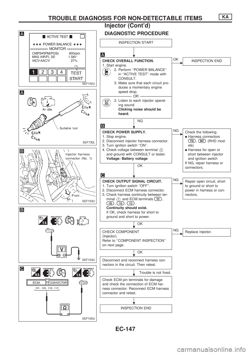
DIAGNOSTIC PROCEDURE
INSPECTION START
CHECK OVERALL FUNCTION.
1. Start engine.
2. Perform ``POWER BALANCE''
in ``ACTIVE TEST'' mode with
CONSULT.
3. Make sure that each circuit pro-
duces a momentary engine
speed drop.
----------------------------------------------------------------------------------------------------------------------------------OR----------------------------------------------------------------------------------------------------------------------------------
2. Listen to each injector operat-
ing sound.
Clicking noise should be
heard.
NG
cOK
INSPECTION END
CHECK POWER SUPPLY.
1. Stop engine.
2. Disconnect injector harness connector.
3. Turn ignition switch ``ON''.
4. Check voltage between terminal
V2
and ground with CONSULT or tester.
Voltage: Battery voltage
OK
cNG
Check the following.
lHarness connectorsF55,M47(RHD mod-
els)
lHarness for open or
short between injector
and ignition switch
If NG, repair harness or
connectors.
CHECK OUTPUT SIGNAL CIRCUIT.
1. Turn ignition switch ``OFF''.
2. Disconnect ECM harness connector.
3. Check harness continuity between ter-
minal
V1and ECM terminals101,103,110,112.
Continuity should exist.
If OK, check harness for short to
ground and short to power.
OK
cNG
Repair open circuit, short
to ground or short to
power in harness or con-
nectors.
CHECK COMPONENT
(Injector).
Refer to ``COMPONENT INSPECTION''
on next page.
OK
cNG
Replace injector.
Disconnect and reconnect harness con-
nectors in the circuit. Then retest.
Trouble is not fixed.
Check ECM pin terminals for damage
and check the connection of ECM har-
ness connector. Reconnect ECM harness
connector and retest.
INSPECTION END
SEF102U
SEF730L
SEF103U
SEF104U
SEF105U
.
.
.
.
.
.
.
TROUBLE DIAGNOSIS FOR NON-DETECTABLE ITEMSKA
Injector (Cont'd)
EC-147
Page 311 of 1659
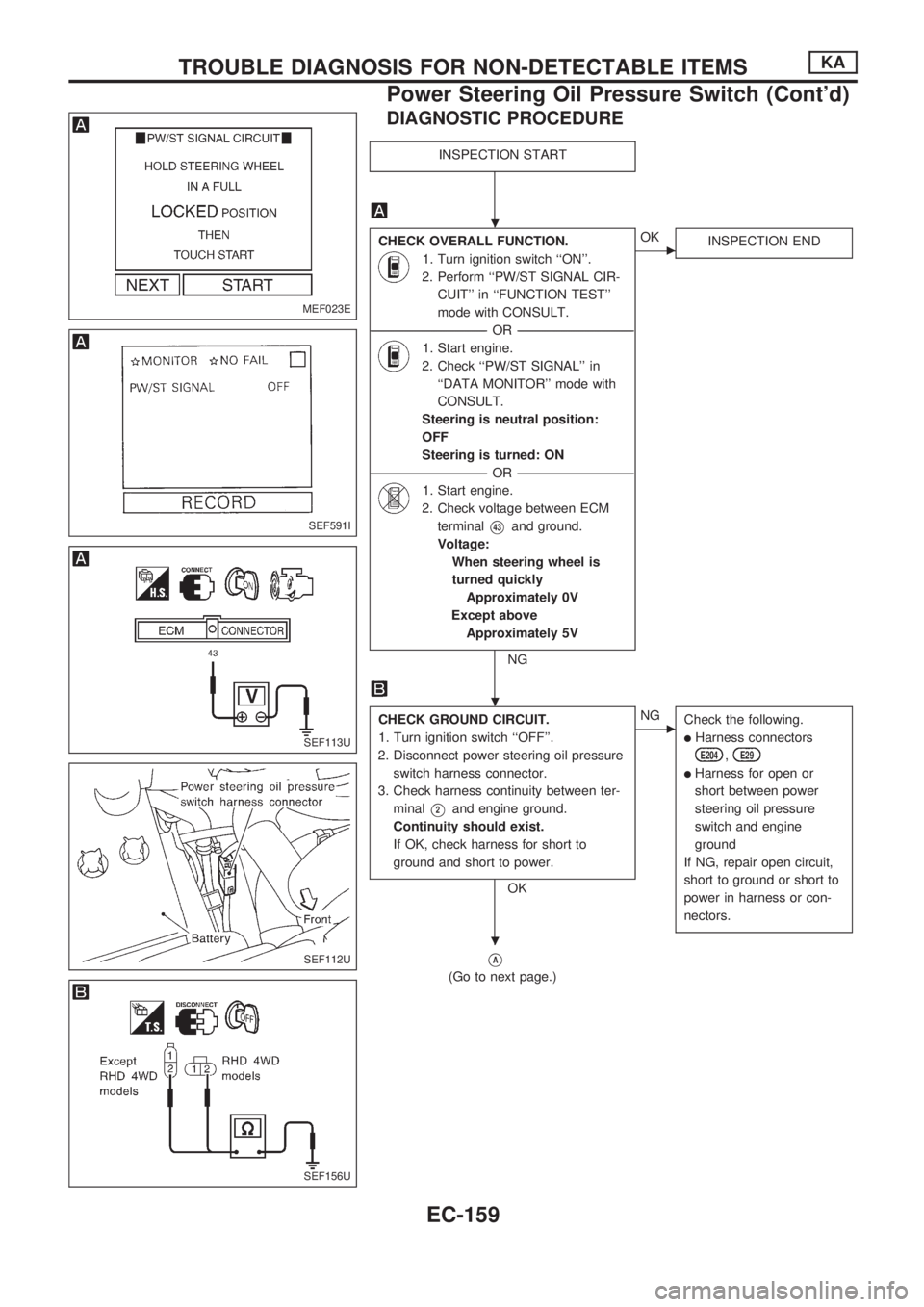
DIAGNOSTIC PROCEDURE
INSPECTION START
CHECK OVERALL FUNCTION.
1. Turn ignition switch ``ON''.
2. Perform ``PW/ST SIGNAL CIR-
CUIT'' in ``FUNCTION TEST''
mode with CONSULT.
----------------------------------------------------------------------------------------------------------------------------------OR----------------------------------------------------------------------------------------------------------------------------------
1. Start engine.
2. Check ``PW/ST SIGNAL'' in
``DATA MONITOR'' mode with
CONSULT.
Steering is neutral position:
OFF
Steering is turned: ON
----------------------------------------------------------------------------------------------------------------------------------OR----------------------------------------------------------------------------------------------------------------------------------
1. Start engine.
2. Check voltage between ECM
terminal
V43and ground.
Voltage:
When steering wheel is
turned quickly
Approximately 0V
Except above
Approximately 5V
NG
cOK
INSPECTION END
CHECK GROUND CIRCUIT.
1. Turn ignition switch ``OFF''.
2. Disconnect power steering oil pressure
switch harness connector.
3. Check harness continuity between ter-
minal
V2and engine ground.
Continuity should exist.
If OK, check harness for short to
ground and short to power.
OK
cNG
Check the following.
lHarness connectors
E204,E29
lHarness for open or
short between power
steering oil pressure
switch and engine
ground
If NG, repair open circuit,
short to ground or short to
power in harness or con-
nectors.
VA
(Go to next page.)
MEF023E
SEF591I
SEF113U
SEF112U
SEF156U
.
.
.
TROUBLE DIAGNOSIS FOR NON-DETECTABLE ITEMSKA
Power Steering Oil Pressure Switch (Cont'd)
EC-159
Page 312 of 1659
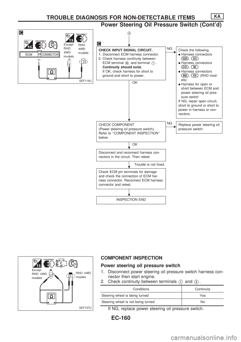
VA
CHECK INPUT SIGNAL CIRCUIT.
1. Disconnect ECM harness connector.
2. Check harness continuity between
ECM terminal
V43and terminalV1.
Continuity should exist.
If OK, check harness for short to
ground and short to power.
OK
cNG
Check the following.
lHarness connectorsE205,E33
lHarness connectorsE101,M5
lHarness connectorsM48,F54(RHD mod-
els)
lHarness for open or
short between ECM and
power steering oil pres-
sure switch
If NG, repair open circuit,
short to ground or short to
power in harness or con-
nectors.
CHECK COMPONENT
(Power steering oil pressure switch).
Refer to ``COMPONENT INSPECTION''
below.
OK
cNG
Replace power steering oil
pressure switch.
Disconnect and reconnect harness con-
nectors in the circuit. Then retest.
Trouble is not fixed.
Check ECM pin terminals for damage
and check the connection of ECM har-
ness connector. Reconnect ECM harness
connector and retest.
INSPECTION END
COMPONENT INSPECTION
Power steering oil pressure switch
1. Disconnect power steering oil pressure switch harness con-
nector then start engine.
2. Check continuity between terminals
V1andV2.
Conditions Continuity
Steering wheel is being turned Yes
Steering wheel is not being turned No
If NG, replace power steering oil pressure switch.
SEF114U
SEF157U
.
.
.
.
.
TROUBLE DIAGNOSIS FOR NON-DETECTABLE ITEMSKA
Power Steering Oil Pressure Switch (Cont'd)
EC-160
Page 316 of 1659
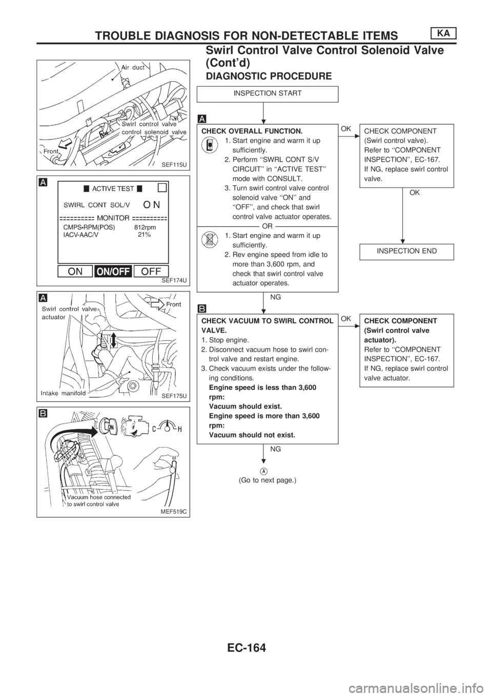
DIAGNOSTIC PROCEDURE
INSPECTION START
CHECK OVERALL FUNCTION.
1. Start engine and warm it up
sufficiently.
2. Perform ``SWRL CONT S/V
CIRCUIT'' in ``ACTIVE TEST''
mode with CONSULT.
3. Turn swirl control valve control
solenoid valve ``ON'' and
``OFF'', and check that swirl
control valve actuator operates.
----------------------------------------------------------------------------------------------------------------------------------OR----------------------------------------------------------------------------------------------------------------------------------
1. Start engine and warm it up
sufficiently.
2. Rev engine speed from idle to
more than 3,600 rpm, and
check that swirl control valve
actuator operates.
NG
cOK
CHECK COMPONENT
(Swirl control valve).
Refer to ``COMPONENT
INSPECTION'', EC-167.
If NG, replace swirl control
valve.
OK
INSPECTION END
CHECK VACUUM TO SWIRL CONTROL
VALVE.
1. Stop engine.
2. Disconnect vacuum hose to swirl con-
trol valve and restart engine.
3. Check vacuum exists under the follow-
ing conditions.
Engine speed is less than 3,600
rpm:
Vacuum should exist.
Engine speed is more than 3,600
rpm:
Vacuum should not exist.
NG
cOK
CHECK COMPONENT
(Swirl control valve
actuator).
Refer to ``COMPONENT
INSPECTION'', EC-167.
If NG, replace swirl control
valve actuator.
VA
(Go to next page.)
SEF115U
SEF174U
SEF175U
MEF519C
.
.
.
.
TROUBLE DIAGNOSIS FOR NON-DETECTABLE ITEMSKA
Swirl Control Valve Control Solenoid Valve
(Cont'd)
EC-164
Page 317 of 1659
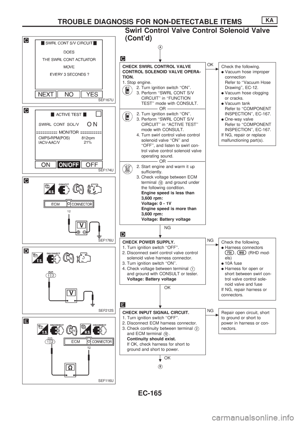
VA
CHECK SWIRL CONTROL VALVE
CONTROL SOLENOID VALVE OPERA-
TION.
1. Stop engine.
2. Turn ignition switch ``ON''.
3. Perform ``SWRL CONT S/V
CIRCUIT'' in ``FUNCTION
TEST'' mode with CONSULT.
----------------------------------------------------------------------------------------------------------------------------------OR----------------------------------------------------------------------------------------------------------------------------------
2. Turn ignition switch ``ON''.
3. Perform ``SWRL CONT S/V
CIRCUIT'' in ``ACTIVE TEST''
mode with CONSULT.
4. Turn swirl control valve control
solenoid valve ``ON'' and
``OFF'', and listen to swirl con-
trol valve control solenoid valve
operating sound.
----------------------------------------------------------------------------------------------------------------------------------OR----------------------------------------------------------------------------------------------------------------------------------
2. Start engine and warm it up
sufficiently.
3. Check voltage between ECM
terminal
V12and ground under
the following condition.
Engine speed is less than
3,600 rpm:
Voltage:0-1V
Engine speed is more than
3,600 rpm:
Voltage: Battery voltage
NG
cOK
Check the following.
lVacuum hose improper
connection
Refer to ``Vacuum Hose
Drawing'', EC-12.
lVacuum hose clogging
or cracks.
lVacuum tank
Refer to ``COMPONENT
INSPECTION'', EC-167.
lOne-way valve
Refer to ``COMPONENT
INSPECTION'', EC-167.
If NG, repair or replace
malfunctioning part(s).
CHECK POWER SUPPLY.
1. Turn ignition switch ``OFF''.
2. Disconnect swirl control valve control
solenoid valve harness connector.
3. Turn ignition switch ``ON''.
4. Check voltage between terminal
V1
and ground with CONSULT or tester.
Voltage: Battery voltage
OK
cNG
Check the following.
lHarness connectorsF54,M48(RHD mod-
els)
l10A fuse
lHarness for open or
short between swirl con-
trol valve control sole-
noid valve and fuse
If NG, repair harness or
connectors.
CHECK INPUT SIGNAL CIRCUIT.
1. Turn ignition switch ``OFF''.
2. Disconnect ECM harness connector.
3. Check continuity between terminal
V2
and ECM terminalV12.
Continuity should exist.
If OK, check harness for short to
ground and short to power.
OK
cNG
Repair open circuit, short
to ground or short to
power in harness or con-
nectors.
VB
SEF167U
SEF174U
SEF176U
SEF212S
SEF116U
.
.
.
.
TROUBLE DIAGNOSIS FOR NON-DETECTABLE ITEMSKA
Swirl Control Valve Control Solenoid Valve
(Cont'd)
EC-165
Page 323 of 1659
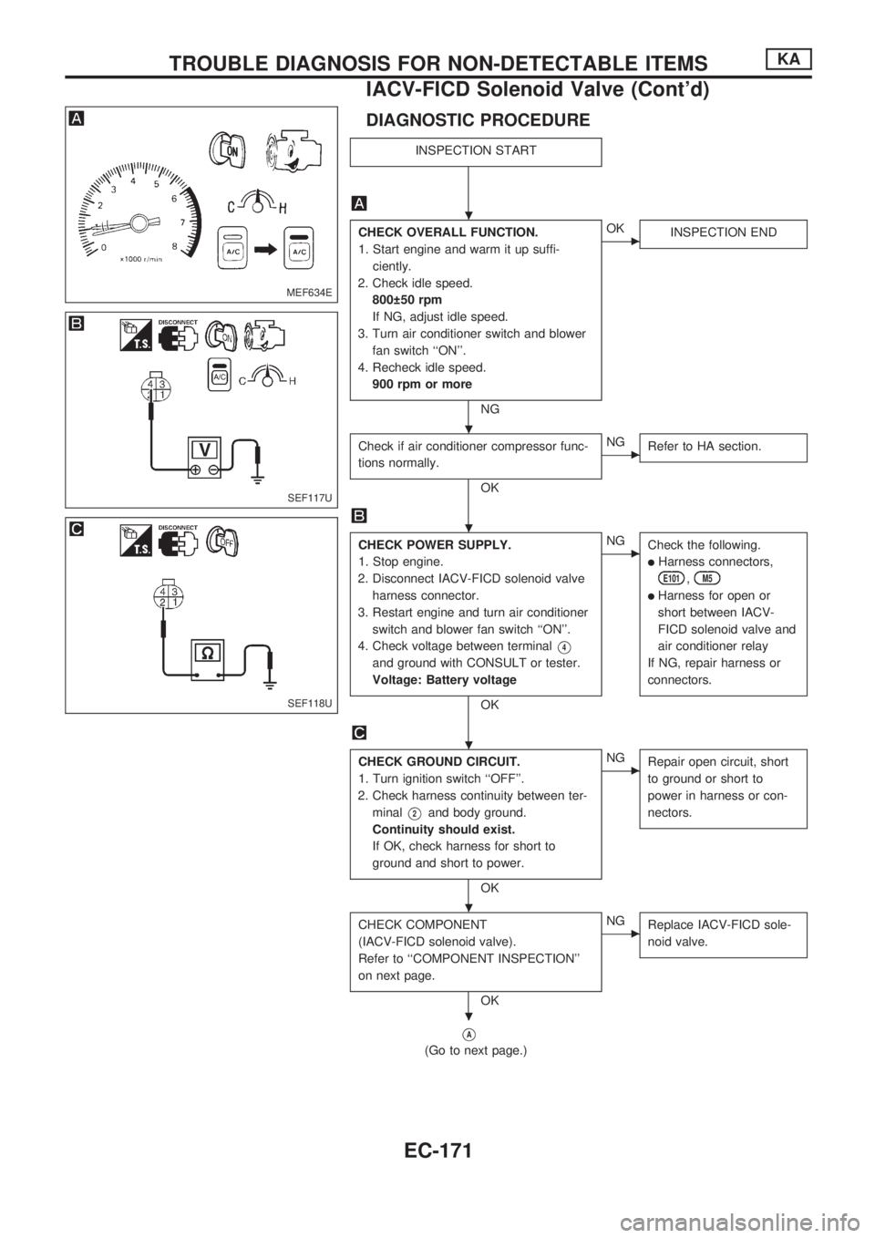
DIAGNOSTIC PROCEDURE
INSPECTION START
CHECK OVERALL FUNCTION.
1. Start engine and warm it up suffi-
ciently.
2. Check idle speed.
800 50 rpm
If NG, adjust idle speed.
3. Turn air conditioner switch and blower
fan switch ``ON''.
4. Recheck idle speed.
900 rpm or more
NG
cOK
INSPECTION END
Check if air conditioner compressor func-
tions normally.
OK
cNG
Refer to HA section.
CHECK POWER SUPPLY.
1. Stop engine.
2. Disconnect IACV-FICD solenoid valve
harness connector.
3. Restart engine and turn air conditioner
switch and blower fan switch ``ON''.
4. Check voltage between terminal
V4
and ground with CONSULT or tester.
Voltage: Battery voltage
OK
cNG
Check the following.
lHarness connectors,
E101,M5
lHarness for open or
short between IACV-
FICD solenoid valve and
air conditioner relay
If NG, repair harness or
connectors.
CHECK GROUND CIRCUIT.
1. Turn ignition switch ``OFF''.
2. Check harness continuity between ter-
minal
V2and body ground.
Continuity should exist.
If OK, check harness for short to
ground and short to power.
OK
cNG
Repair open circuit, short
to ground or short to
power in harness or con-
nectors.
CHECK COMPONENT
(IACV-FICD solenoid valve).
Refer to ``COMPONENT INSPECTION''
on next page.
OK
cNG
Replace IACV-FICD sole-
noid valve.
VA
(Go to next page.)
MEF634E
SEF117U
SEF118U
.
.
.
.
.
.
TROUBLE DIAGNOSIS FOR NON-DETECTABLE ITEMSKA
IACV-FICD Solenoid Valve (Cont'd)
EC-171