1998 NISSAN PICK-UP check engine
[x] Cancel search: check enginePage 209 of 1659
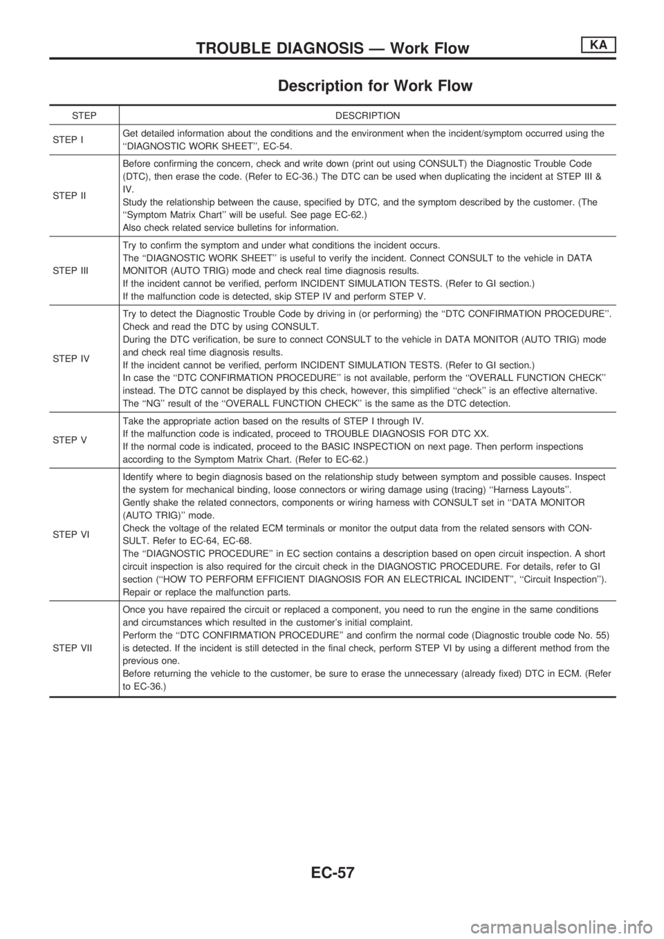
Description for Work Flow
STEP DESCRIPTION
STEP IGet detailed information about the conditions and the environment when the incident/symptom occurred using the
``DIAGNOSTIC WORK SHEET'', EC-54.
STEP IIBefore confirming the concern, check and write down (print out using CONSULT) the Diagnostic Trouble Code
(DTC), then erase the code. (Refer to EC-36.) The DTC can be used when duplicating the incident at STEP III &
IV.
Study the relationship between the cause, specified by DTC, and the symptom described by the customer. (The
``Symptom Matrix Chart'' will be useful. See page EC-62.)
Also check related service bulletins for information.
STEP IIITry to confirm the symptom and under what conditions the incident occurs.
The ``DIAGNOSTIC WORK SHEET'' is useful to verify the incident. Connect CONSULT to the vehicle in DATA
MONITOR (AUTO TRIG) mode and check real time diagnosis results.
If the incident cannot be verified, perform INCIDENT SIMULATION TESTS. (Refer to GI section.)
If the malfunction code is detected, skip STEP IV and perform STEP V.
STEP IVTry to detect the Diagnostic Trouble Code by driving in (or performing) the ``DTC CONFIRMATION PROCEDURE''.
Check and read the DTC by using CONSULT.
During the DTC verification, be sure to connect CONSULT to the vehicle in DATA MONITOR (AUTO TRIG) mode
and check real time diagnosis results.
If the incident cannot be verified, perform INCIDENT SIMULATION TESTS. (Refer to GI section.)
In case the ``DTC CONFIRMATION PROCEDURE'' is not available, perform the ``OVERALL FUNCTION CHECK''
instead. The DTC cannot be displayed by this check, however, this simplified ``check'' is an effective alternative.
The ``NG'' result of the ``OVERALL FUNCTION CHECK'' is the same as the DTC detection.
STEP VTake the appropriate action based on the results of STEP I through IV.
If the malfunction code is indicated, proceed to TROUBLE DIAGNOSIS FOR DTC XX.
If the normal code is indicated, proceed to the BASIC INSPECTION on next page. Then perform inspections
according to the Symptom Matrix Chart. (Refer to EC-62.)
STEP VIIdentify where to begin diagnosis based on the relationship study between symptom and possible causes. Inspect
the system for mechanical binding, loose connectors or wiring damage using (tracing) ``Harness Layouts''.
Gently shake the related connectors, components or wiring harness with CONSULT set in ``DATA MONITOR
(AUTO TRIG)'' mode.
Check the voltage of the related ECM terminals or monitor the output data from the related sensors with CON-
SULT. Refer to EC-64, EC-68.
The ``DIAGNOSTIC PROCEDURE'' in EC section contains a description based on open circuit inspection. A short
circuit inspection is also required for the circuit check in the DIAGNOSTIC PROCEDURE. For details, refer to GI
section (``HOW TO PERFORM EFFICIENT DIAGNOSIS FOR AN ELECTRICAL INCIDENT'', ``Circuit Inspection'').
Repair or replace the malfunction parts.
STEP VIIOnce you have repaired the circuit or replaced a component, you need to run the engine in the same conditions
and circumstances which resulted in the customer's initial complaint.
Perform the ``DTC CONFIRMATION PROCEDURE'' and confirm the normal code (Diagnostic trouble code No. 55)
is detected. If the incident is still detected in the final check, perform STEP VI by using a different method from the
previous one.
Before returning the vehicle to the customer, be sure to erase the unnecessary (already fixed) DTC in ECM. (Refer
to EC-36.)
TROUBLE DIAGNOSIS Ð Work FlowKA
EC-57
Page 210 of 1659
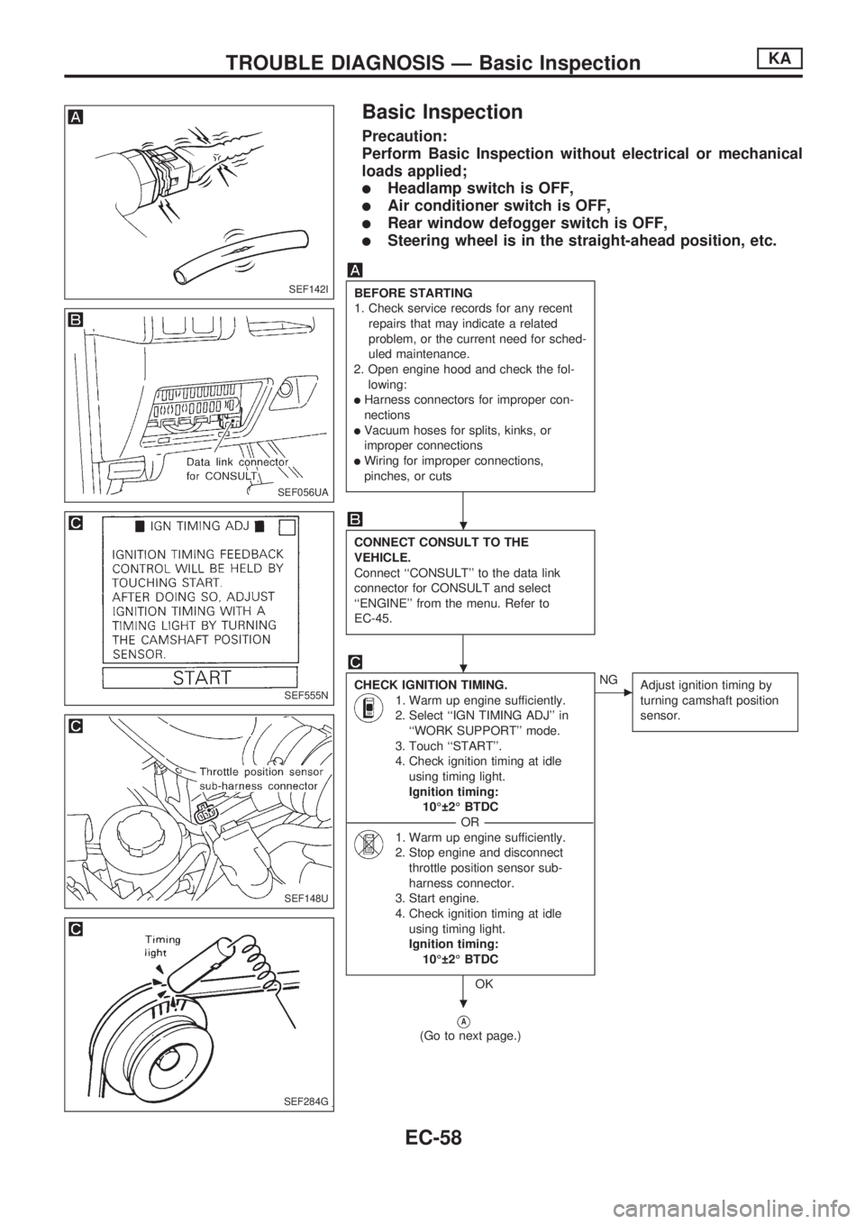
Basic Inspection
Precaution:
Perform Basic Inspection without electrical or mechanical
loads applied;
lHeadlamp switch is OFF,
lAir conditioner switch is OFF,
lRear window defogger switch is OFF,
lSteering wheel is in the straight-ahead position, etc.
BEFORE STARTING
1. Check service records for any recent
repairs that may indicate a related
problem, or the current need for sched-
uled maintenance.
2. Open engine hood and check the fol-
lowing:
lHarness connectors for improper con-
nections
lVacuum hoses for splits, kinks, or
improper connections
lWiring for improper connections,
pinches, or cuts
CONNECT CONSULT TO THE
VEHICLE.
Connect ``CONSULT'' to the data link
connector for CONSULT and select
``ENGINE'' from the menu. Refer to
EC-45.
CHECK IGNITION TIMING.
1. Warm up engine sufficiently.
2. Select ``IGN TIMING ADJ'' in
``WORK SUPPORT'' mode.
3. Touch ``START''.
4. Check ignition timing at idle
using timing light.
Ignition timing:
10É 2É BTDC
----------------------------------------------------------------------------------------------------------------------------------OR----------------------------------------------------------------------------------------------------------------------------------
1. Warm up engine sufficiently.
2. Stop engine and disconnect
throttle position sensor sub-
harness connector.
3. Start engine.
4. Check ignition timing at idle
using timing light.
Ignition timing:
10É 2É BTDC
OK
cNG
Adjust ignition timing by
turning camshaft position
sensor.
VA
(Go to next page.)
SEF142I
SEF056UA
SEF555N
SEF148U
SEF284G
.
.
.
TROUBLE DIAGNOSIS Ð Basic InspectionKA
EC-58
Page 211 of 1659
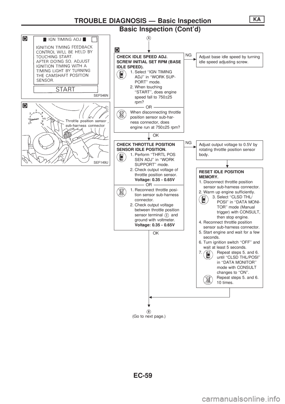
VA
CHECK IDLE SPEED ADJ.
SCREW INITIAL SET RPM (BASE
IDLE SPEED).
1. Select ``IGN TIMING
ADJ'' in ``WORK SUP-
PORT'' mode.
2. When touching
``START'', does engine
speed fall to 750 25
rpm?
-----------------------------------------------------------------------------------------------------------OR -----------------------------------------------------------------------------------------------------------
When disconnecting throttle
position sensor sub-har-
ness connector, does
engine run at 750 25 rpm?
OK
cNG
Adjust base idle speed by turning
idle speed adjusting screw.
CHECK THROTTLE POSITION
SENSOR IDLE POSITION.
1. Perform ``THRTL POS
SEN ADJ'' in ``WORK
SUPPORT'' mode.
2. Check output voltage of
throttle position sensor.
Voltage: 0.35 - 0.65V
-----------------------------------------------------------------------------------------------------------OR -----------------------------------------------------------------------------------------------------------
1. Reconnect throttle posi-
tion sensor sub-harness
connector.
2. Check output voltage
between throttle position
sensor terminal
V2and
ground with voltmeter.
Voltage: 0.35 - 0.65V
OK
cNG
Adjust output voltage to 0.5V by
rotating throttle position sensor
body.
RESET IDLE POSITION
MEMORY.
1. Disconnect throttle position
sensor sub-harness connector.
2. Warm up engine sufficiently.
3. Select ``CLSD THL/
POSI'' in ``DATA MONI-
TOR'' mode (Manual
trigger) with CONSULT,
then stop engine.
4. Reconnect throttle position
sensor sub-harness connector.
5. Start engine and wait for a few
seconds.
6. Turn ignition switch ``OFF'' and
wait at least 5 seconds.
7.
Repeat steps 5. and 6.
until ``CLSD THL/POSI''
in ``DATA MONITOR''
mode with CONSULT
changes to ``ON''.
Repeat steps 5. and 6.
10 times.
b
VB
(Go to next page.)
SEF546N
SEF149U
.
.
.
.
TROUBLE DIAGNOSIS Ð Basic InspectionKA
Basic Inspection (Cont'd)
EC-59
Page 212 of 1659
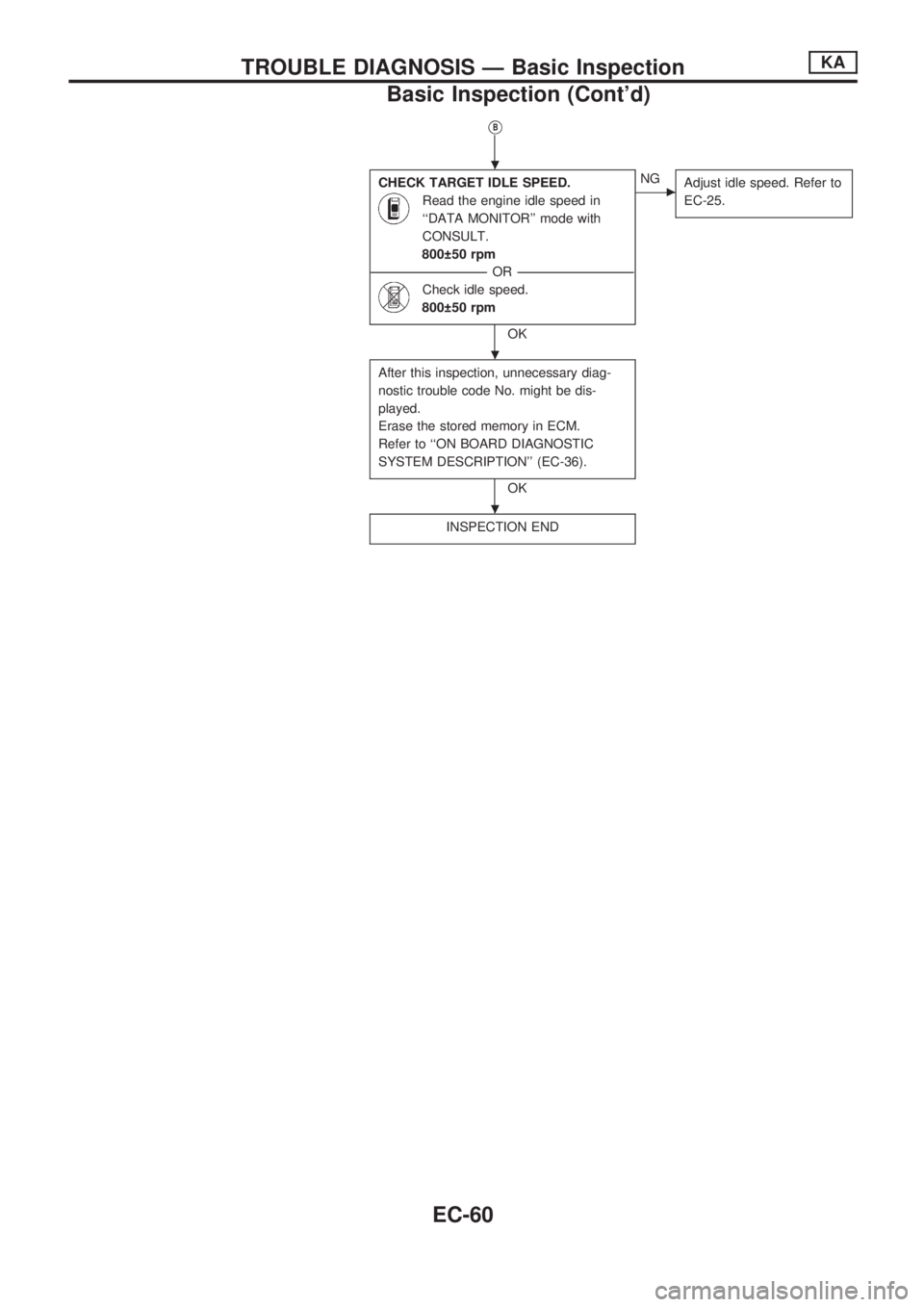
VB
CHECK TARGET IDLE SPEED.
Read the engine idle speed in
``DATA MONITOR'' mode with
CONSULT.
800 50 rpm
----------------------------------------------------------------------------------------------------------------------------------OR----------------------------------------------------------------------------------------------------------------------------------
Check idle speed.
800 50 rpm
OK
cNG
Adjust idle speed. Refer to
EC-25.
After this inspection, unnecessary diag-
nostic trouble code No. might be dis-
played.
Erase the stored memory in ECM.
Refer to ``ON BOARD DIAGNOSTIC
SYSTEM DESCRIPTION'' (EC-36).
OK
INSPECTION END
.
.
.
TROUBLE DIAGNOSIS Ð Basic InspectionKA
Basic Inspection (Cont'd)
EC-60
Page 216 of 1659
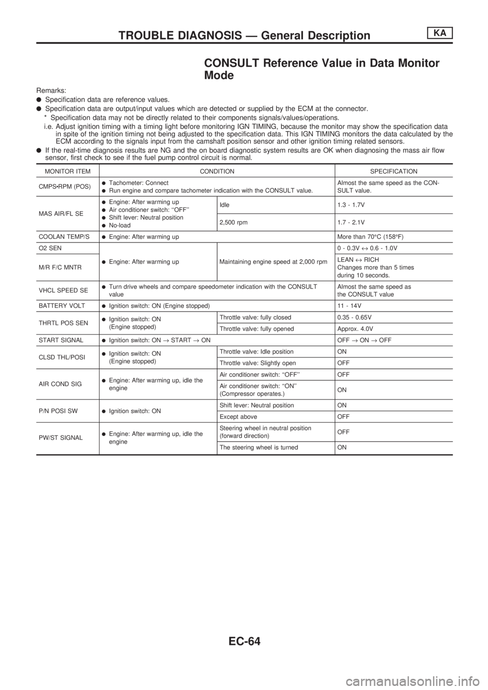
CONSULT Reference Value in Data Monitor
Mode
Remarks:
lSpecification data are reference values.
lSpecification data are output/input values which are detected or supplied by the ECM at the connector.
* Specification data may not be directly related to their components signals/values/operations.
i.e. Adjust ignition timing with a timing light before monitoring IGN TIMING, because the monitor may show the specification data
in spite of the ignition timing not being adjusted to the specification data. This IGN TIMING monitors the data calculated by the
ECM according to the signals input from the camshaft position sensor and other ignition timing related sensors.
lIf the real-time diagnosis results are NG and the on board diagnostic system results are OK when diagnosing the mass air flow
sensor, first check to see if the fuel pump control circuit is normal.
MONITOR ITEM CONDITION SPECIFICATION
CMPScRPM (POS)
lTachometer: ConnectlRun engine and compare tachometer indication with the CONSULT value.Almost the same speed as the CON-
SULT value.
MAS AIR/FL SE
lEngine: After warming uplAir conditioner switch: ``OFF''lShift lever: Neutral positionlNo-loadIdle 1.3 - 1.7V
2,500 rpm 1.7 - 2.1V
COOLAN TEMP/S
lEngine: After warming up More than 70ÉC (158ÉF)
O2 SEN
lEngine: After warming up Maintaining engine speed at 2,000 rpm0 - 0.3V«0.6 - 1.0V
M/R F/C MNTRLEAN«RICH
Changes more than 5 times
during 10 seconds.
VHCL SPEED SE
lTurn drive wheels and compare speedometer indication with the CONSULT
valueAlmost the same speed as
the CONSULT value
BATTERY VOLT
lIgnition switch: ON (Engine stopped) 11 - 14V
THRTL POS SEN
lIgnition switch: ON
(Engine stopped)Throttle valve: fully closed 0.35 - 0.65V
Throttle valve: fully opened Approx. 4.0V
START SIGNAL
lIgnition switch: ON®START®ON OFF®ON®OFF
CLSD THL/POSI
lIgnition switch: ON
(Engine stopped)Throttle valve: Idle position ON
Throttle valve: Slightly open OFF
AIR COND SIG
lEngine: After warming up, idle the
engineAir conditioner switch: ``OFF'' OFF
Air conditioner switch: ``ON''
(Compressor operates.)ON
P/N POSI SW
lIgnition switch: ONShift lever: Neutral position ON
Except above OFF
PW/ST SIGNAL
lEngine: After warming up, idle the
engineSteering wheel in neutral position
(forward direction)OFF
The steering wheel is turned ON
TROUBLE DIAGNOSIS Ð General DescriptionKA
EC-64
Page 221 of 1659
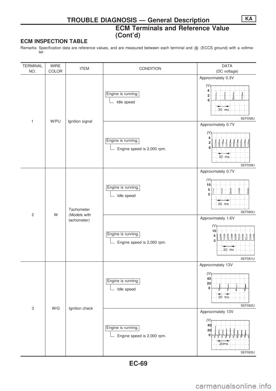
ECM INSPECTION TABLE
Remarks: Specification data are reference values, and are measured between each terminal andV39(ECCS ground) with a voltme-
ter.
TERMINAL
NO.WIRE
COLORITEM CONDITIONDATA
(DC voltage)
1 W/PU Ignition signalEngine is running.
Idle speedApproximately 0.3V
SEF058U
Engine is running.
Engine speed is 2,000 rpm.Approximately 0.7V
SEF059U
2WTachometer
(Models with
tachometer)Engine is running.
Idle speedApproximately 0.7V
SEF060U
Engine is running.
Engine speed is 2,000 rpm.Approximately 1.6V
SEF061U
3 W/G Ignition checkEngine is running.
Idle speedApproximately 13V
SEF062U
Engine is running.
Engine speed is 2,000 rpm.Approximately 13V
SEF063U
TROUBLE DIAGNOSIS Ð General DescriptionKA
ECM Terminals and Reference Value
(Cont'd)
EC-69
Page 232 of 1659
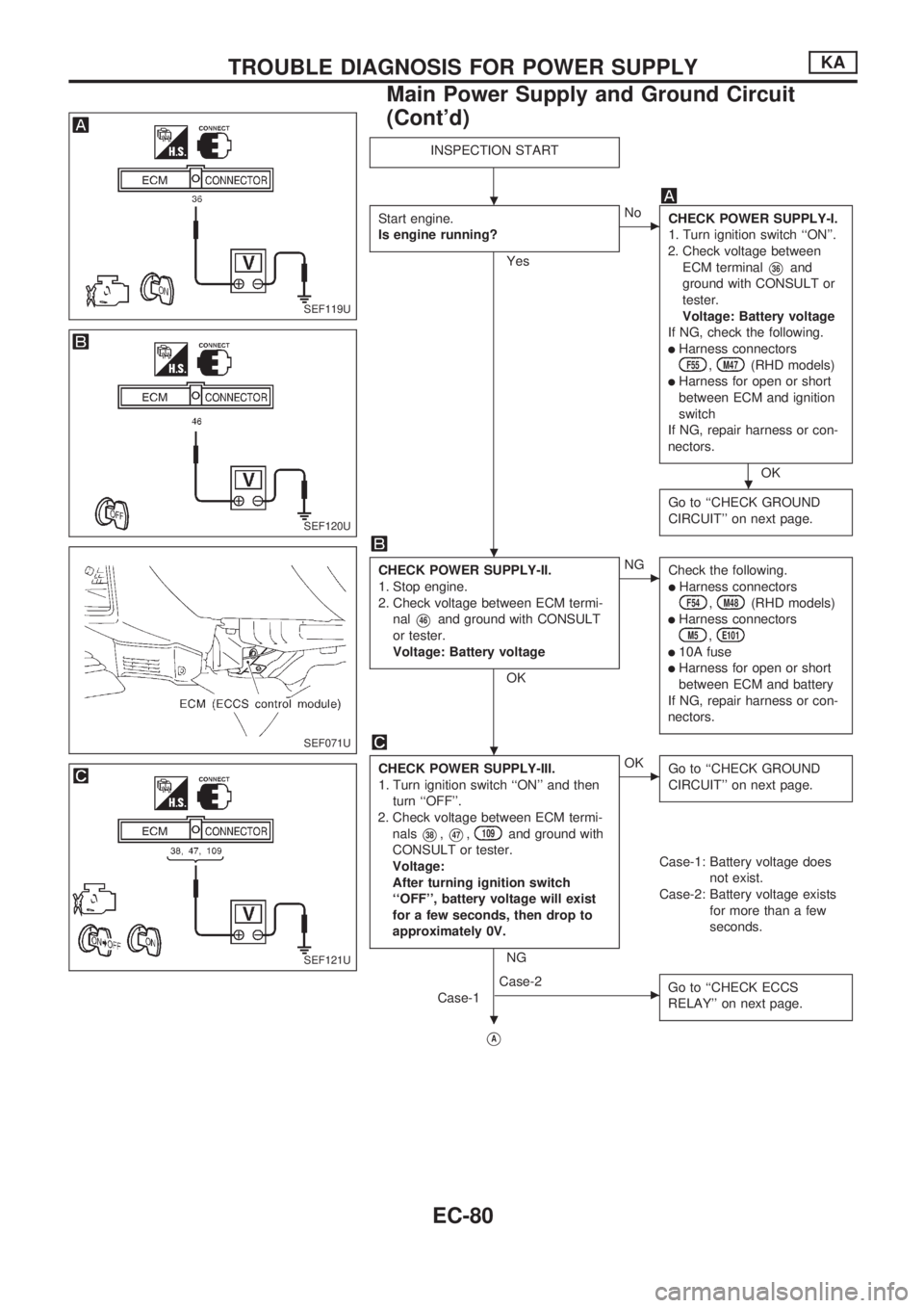
INSPECTION START
Start engine.
Is engine running?
Yes
cNo
CHECK POWER SUPPLY-I.
1. Turn ignition switch ``ON''.
2. Check voltage between
ECM terminal
V36and
ground with CONSULT or
tester.
Voltage: Battery voltage
If NG, check the following.
lHarness connectorsF55,M47(RHD models)
lHarness for open or short
between ECM and ignition
switch
If NG, repair harness or con-
nectors.
OK
Go to ``CHECK GROUND
CIRCUIT'' on next page.
CHECK POWER SUPPLY-II.
1. Stop engine.
2. Check voltage between ECM termi-
nal
V46and ground with CONSULT
or tester.
Voltage: Battery voltage
OK
cNG
Check the following.
lHarness connectorsF54,M48(RHD models)
lHarness connectorsM5,E101
l10A fuse
lHarness for open or short
between ECM and battery
If NG, repair harness or con-
nectors.
CHECK POWER SUPPLY-III.
1. Turn ignition switch ``ON'' and then
turn ``OFF''.
2. Check voltage between ECM termi-
nals
V38,V47,109and ground with
CONSULT or tester.
Voltage:
After turning ignition switch
``OFF'', battery voltage will exist
for a few seconds, then drop to
approximately 0V.
NG
cOK
Go to ``CHECK GROUND
CIRCUIT'' on next page.
Case-1: Battery voltage does
not exist.
Case-2: Battery voltage exists
for more than a few
seconds.
Case-1
cCase-2
Go to ``CHECK ECCS
RELAY'' on next page.
VA
SEF119U
SEF120U
SEF071U
SEF121U
.
.
.
.
.
TROUBLE DIAGNOSIS FOR POWER SUPPLYKA
Main Power Supply and Ground Circuit
(Cont'd)
EC-80
Page 233 of 1659
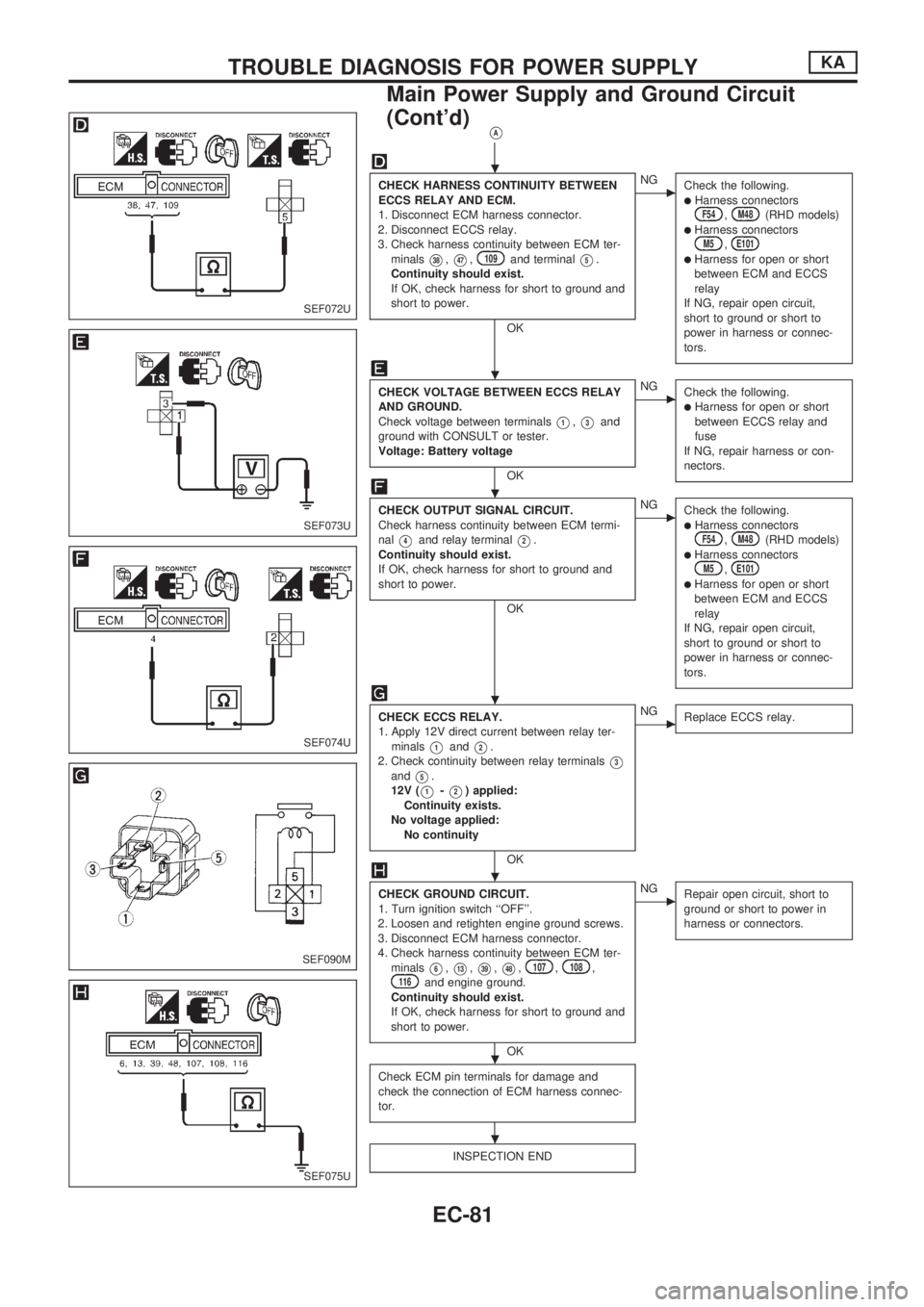
VA
CHECK HARNESS CONTINUITY BETWEEN
ECCS RELAY AND ECM.
1. Disconnect ECM harness connector.
2. Disconnect ECCS relay.
3. Check harness continuity between ECM ter-
minals
V38,V47,109and terminalV5.
Continuity should exist.
If OK, check harness for short to ground and
short to power.
OK
cNG
Check the following.
lHarness connectorsF54,M48(RHD models)lHarness connectorsM5,E101lHarness for open or short
between ECM and ECCS
relay
If NG, repair open circuit,
short to ground or short to
power in harness or connec-
tors.
CHECK VOLTAGE BETWEEN ECCS RELAY
AND GROUND.
Check voltage between terminals
V1,V3and
ground with CONSULT or tester.
Voltage: Battery voltage
OK
cNG
Check the following.
lHarness for open or short
between ECCS relay and
fuse
If NG, repair harness or con-
nectors.
CHECK OUTPUT SIGNAL CIRCUIT.
Check harness continuity between ECM termi-
nal
V4and relay terminalV2.
Continuity should exist.
If OK, check harness for short to ground and
short to power.
OK
cNG
Check the following.
lHarness connectorsF54,M48(RHD models)lHarness connectorsM5,E101lHarness for open or short
between ECM and ECCS
relay
If NG, repair open circuit,
short to ground or short to
power in harness or connec-
tors.
CHECK ECCS RELAY.
1. Apply 12V direct current between relay ter-
minals
V1andV2.
2. Check continuity between relay terminals
V3andV5.
12V (
V1-V2) applied:
Continuity exists.
No voltage applied:
No continuity
OK
cNG
Replace ECCS relay.
CHECK GROUND CIRCUIT.
1. Turn ignition switch ``OFF''.
2. Loosen and retighten engine ground screws.
3. Disconnect ECM harness connector.
4. Check harness continuity between ECM ter-
minals
V6,V13,V39,V48,107,108,116and engine ground.
Continuity should exist.
If OK, check harness for short to ground and
short to power.
OK
cNG
Repair open circuit, short to
ground or short to power in
harness or connectors.
Check ECM pin terminals for damage and
check the connection of ECM harness connec-
tor.
INSPECTION END
SEF072U
SEF073U
SEF074U
SEF090M
SEF075U
.
.
.
.
.
.
.
TROUBLE DIAGNOSIS FOR POWER SUPPLYKA
Main Power Supply and Ground Circuit
(Cont'd)
EC-81