1998 NISSAN PICK-UP check engine
[x] Cancel search: check enginePage 61 of 1659
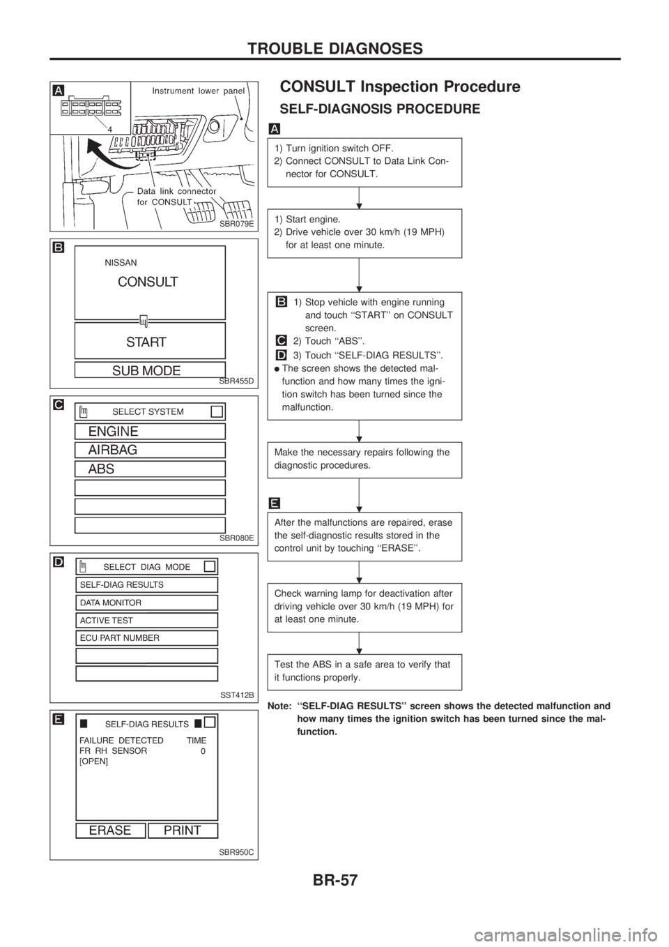
CONSULT Inspection Procedure
SELF-DIAGNOSIS PROCEDURE
1) Turn ignition switch OFF.
2) Connect CONSULT to Data Link Con-
nector for CONSULT.
1) Start engine.
2) Drive vehicle over 30 km/h (19 MPH)
for at least one minute.
1) Stop vehicle with engine running
and touch ``START'' on CONSULT
screen.
2) Touch ``ABS''.
3) Touch ``SELF-DIAG RESULTS''.
lThe screen shows the detected mal-
function and how many times the igni-
tion switch has been turned since the
malfunction.
Make the necessary repairs following the
diagnostic procedures.
After the malfunctions are repaired, erase
the self-diagnostic results stored in the
control unit by touching ``ERASE''.
Check warning lamp for deactivation after
driving vehicle over 30 km/h (19 MPH) for
at least one minute.
Test the ABS in a safe area to verify that
it functions properly.
Note: ``SELF-DIAG RESULTS'' screen shows the detected malfunction and
how many times the ignition switch has been turned since the mal-
function.
SBR079E
SBR455D
SBR080E
SST412B
SBR950C
.
.
.
.
.
.
TROUBLE DIAGNOSES
BR-57
Page 78 of 1659
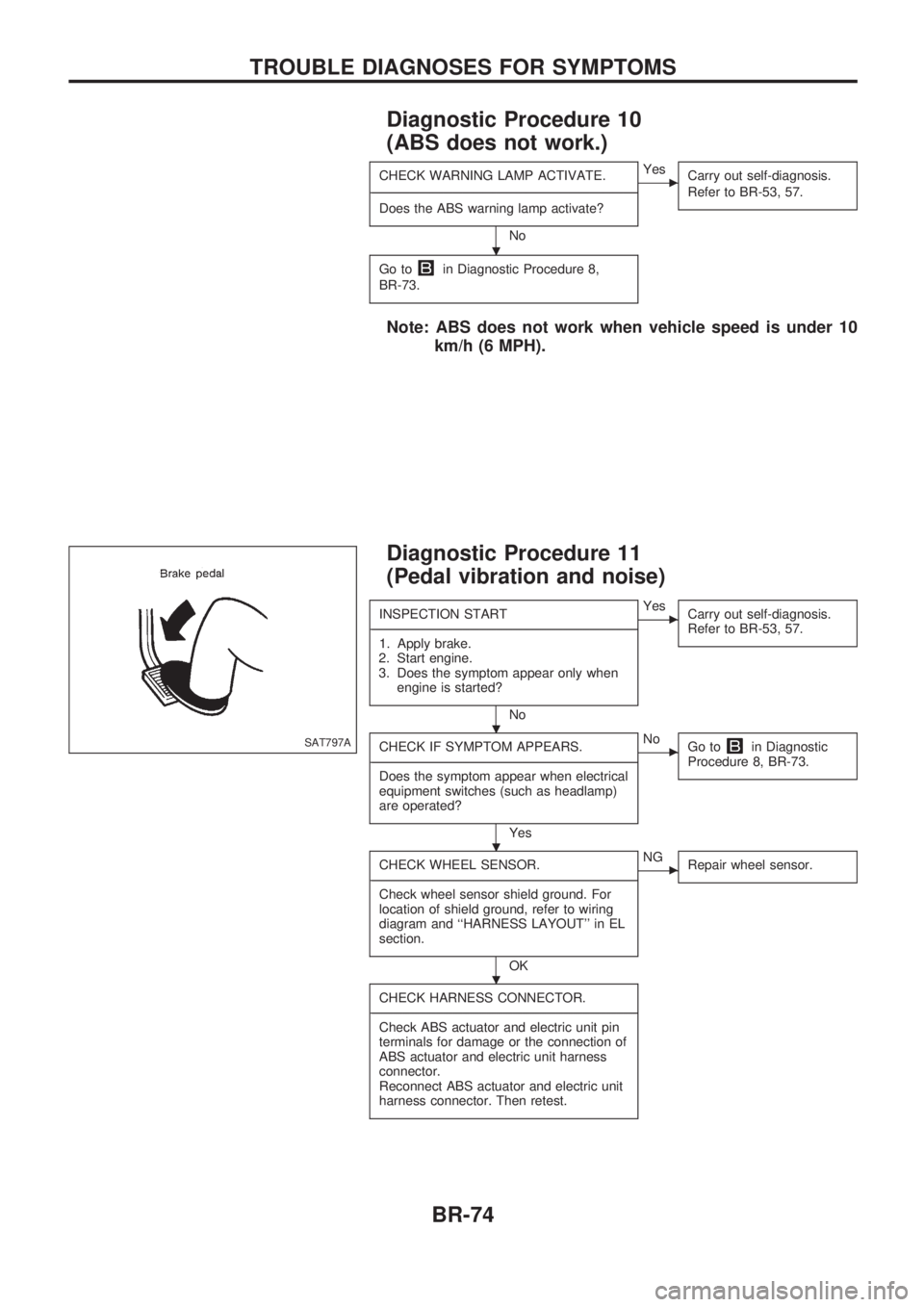
Diagnostic Procedure 10
(ABS does not work.)
CHECK WARNING LAMP ACTIVATE.
-------------------------------------------------------------------------------------------------------------------------------------------------------------------------------------------------------------------------------------------------------------------------------------------------------------
Does the ABS warning lamp activate?
No
cYes
Carry out self-diagnosis.
Refer to BR-53, 57.
Go toin Diagnostic Procedure 8,
BR-73.
Note: ABS does not work when vehicle speed is under 10
km/h (6 MPH).
Diagnostic Procedure 11
(Pedal vibration and noise)
INSPECTION START
-------------------------------------------------------------------------------------------------------------------------------------------------------------------------------------------------------------------------------------------------------------------------------------------------------------
1. Apply brake.
2. Start engine.
3. Does the symptom appear only when
engine is started?
No
cYes
Carry out self-diagnosis.
Refer to BR-53, 57.
CHECK IF SYMPTOM APPEARS.
-------------------------------------------------------------------------------------------------------------------------------------------------------------------------------------------------------------------------------------------------------------------------------------------------------------
Does the symptom appear when electrical
equipment switches (such as headlamp)
are operated?
Yes
cNo
Go toin Diagnostic
Procedure 8, BR-73.
CHECK WHEEL SENSOR.
-------------------------------------------------------------------------------------------------------------------------------------------------------------------------------------------------------------------------------------------------------------------------------------------------------------
Check wheel sensor shield ground. For
location of shield ground, refer to wiring
diagram and ``HARNESS LAYOUT'' in EL
section.
OK
cNG
Repair wheel sensor.
CHECK HARNESS CONNECTOR.
-------------------------------------------------------------------------------------------------------------------------------------------------------------------------------------------------------------------------------------------------------------------------------------------------------------
Check ABS actuator and electric unit pin
terminals for damage or the connection of
ABS actuator and electric unit harness
connector.
Reconnect ABS actuator and electric unit
harness connector. Then retest.
SAT797A
.
.
.
.
TROUBLE DIAGNOSES FOR SYMPTOMS
BR-74
Page 79 of 1659
Note: ABS may operate and cause vibration under any of the
following conditions.
lApplying brake gradually when shifting or operating
clutch.
lLow friction (slippery) road.
lHigh speed cornering.
lDriving over bumps and pot holes.
lEngine speed is over 5,000 rpm with vehicle stopped.
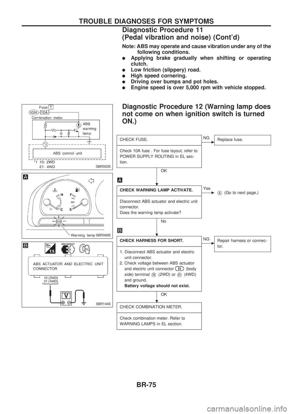
Diagnostic Procedure 12 (Warning lamp does
not come on when ignition switch is turned
ON.)
CHECK FUSE.
-------------------------------------------------------------------------------------------------------------------------------------------------------------------------------------------------------------------------------------------------------------------------------------------------------------
Check 10A fuse . For fuse layout, refer to
POWER SUPPLY ROUTING in EL sec-
tion.
OK
cNG
Replace fuse.
CHECK WARNING LAMP ACTIVATE.
-------------------------------------------------------------------------------------------------------------------------------------------------------------------------------------------------------------------------------------------------------------------------------------------------------------
Disconnect ABS actuator and electric unit
connector.
Does the warning lamp activate?
No
cYes
VA(Go to next page.)
CHECK HARNESS FOR SHORT.
-------------------------------------------------------------------------------------------------------------------------------------------------------------------------------------------------------------------------------------------------------------------------------------------------------------
1. Disconnect ABS actuator and electric
unit connector.
2. Check voltage between ABS actuator
and electric unit connector
E4(body
side) terminal
V10(2WD) orV21(4WD)
and ground.
Battery voltage should not exist.
OK
cNG
Repair harness or connec-
tor.
CHECK COMBINATION METER.
-------------------------------------------------------------------------------------------------------------------------------------------------------------------------------------------------------------------------------------------------------------------------------------------------------------
Check combination meter. Refer to
WARNING LAMPS in EL section.
SBR063E
SBR069E
SBR144E
.
.
.
TROUBLE DIAGNOSES FOR SYMPTOMS
Diagnostic Procedure 11
(Pedal vibration and noise) (Cont'd)
BR-75
Page 93 of 1659
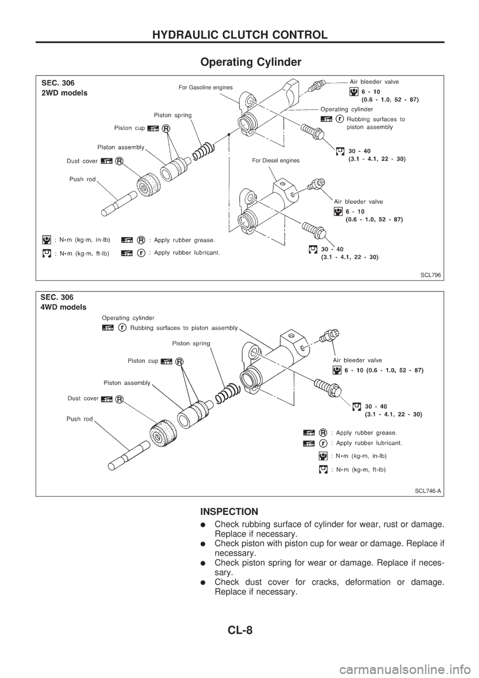
Operating Cylinder
INSPECTION
lCheck rubbing surface of cylinder for wear, rust or damage.
Replace if necessary.
lCheck piston with piston cup for wear or damage. Replace if
necessary.
lCheck piston spring for wear or damage. Replace if neces-
sary.
lCheck dust cover for cracks, deformation or damage.
Replace if necessary.
SCL796
.
For Gasoline engines
.
For Diesel engines
SCL746-A
.
HYDRAULIC CLUTCH CONTROL
CL-8
Page 97 of 1659
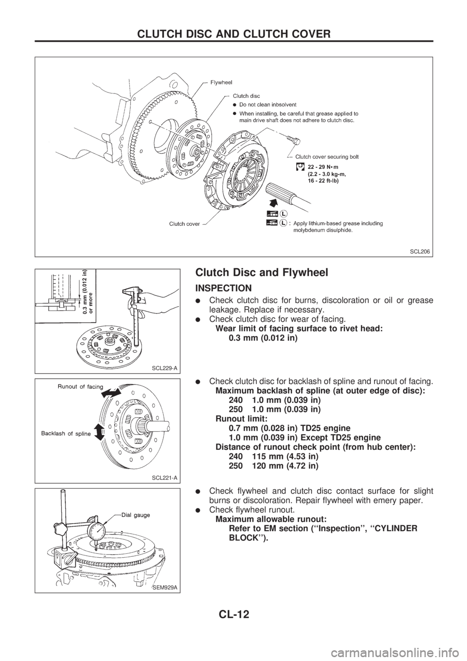
Clutch Disc and Flywheel
INSPECTION
lCheck clutch disc for burns, discoloration or oil or grease
leakage. Replace if necessary.
lCheck clutch disc for wear of facing.
Wear limit of facing surface to rivet head:
0.3 mm (0.012 in)
lCheck clutch disc for backlash of spline and runout of facing.
Maximum backlash of spline (at outer edge of disc):
240 1.0 mm (0.039 in)
250 1.0 mm (0.039 in)
Runout limit:
0.7 mm (0.028 in) TD25 engine
1.0 mm (0.039 in) Except TD25 engine
Distance of runout check point (from hub center):
240 115 mm (4.53 in)
250 120 mm (4.72 in)
lCheck flywheel and clutch disc contact surface for slight
burns or discoloration. Repair flywheel with emery paper.
lCheck flywheel runout.
Maximum allowable runout:
Refer to EM section (``Inspection'', ``CYLINDER
BLOCK'').
SCL206
SCL229-A
SCL221-A
SEM929A
CLUTCH DISC AND CLUTCH COVER
CL-12
Page 98 of 1659
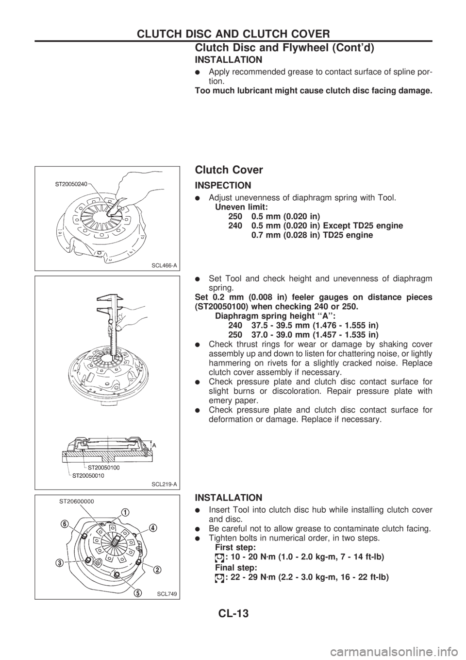
INSTALLATION
lApply recommended grease to contact surface of spline por-
tion.
Too much lubricant might cause clutch disc facing damage.
Clutch Cover
INSPECTION
lAdjust unevenness of diaphragm spring with Tool.
Uneven limit:
250 0.5 mm (0.020 in)
240 0.5 mm (0.020 in) Except TD25 engine
0.7 mm (0.028 in) TD25 engine
lSet Tool and check height and unevenness of diaphragm
spring.
Set 0.2 mm (0.008 in) feeler gauges on distance pieces
(ST20050100) when checking 240 or 250.
Diaphragm spring height ``A'':
240 37.5 - 39.5 mm (1.476 - 1.555 in)
250 37.0 - 39.0 mm (1.457 - 1.535 in)
lCheck thrust rings for wear or damage by shaking cover
assembly up and down to listen for chattering noise, or lightly
hammering on rivets for a slightly cracked noise. Replace
clutch cover assembly if necessary.
lCheck pressure plate and clutch disc contact surface for
slight burns or discoloration. Repair pressure plate with
emery paper.
lCheck pressure plate and clutch disc contact surface for
deformation or damage. Replace if necessary.
INSTALLATION
lInsert Tool into clutch disc hub while installing clutch cover
and disc.
lBe careful not to allow grease to contaminate clutch facing.
lTighten bolts in numerical order, in two steps.
First step:
:10-20Nzm (1.0 - 2.0 kg-m,7-14ft-lb)
Final step:
:22-29Nzm (2.2 - 3.0 kg-m, 16 - 22 ft-lb)
SCL466-A
SCL219-A
SCL749
CLUTCH DISC AND CLUTCH COVER
Clutch Disc and Flywheel (Cont'd)
CL-13
Page 99 of 1659
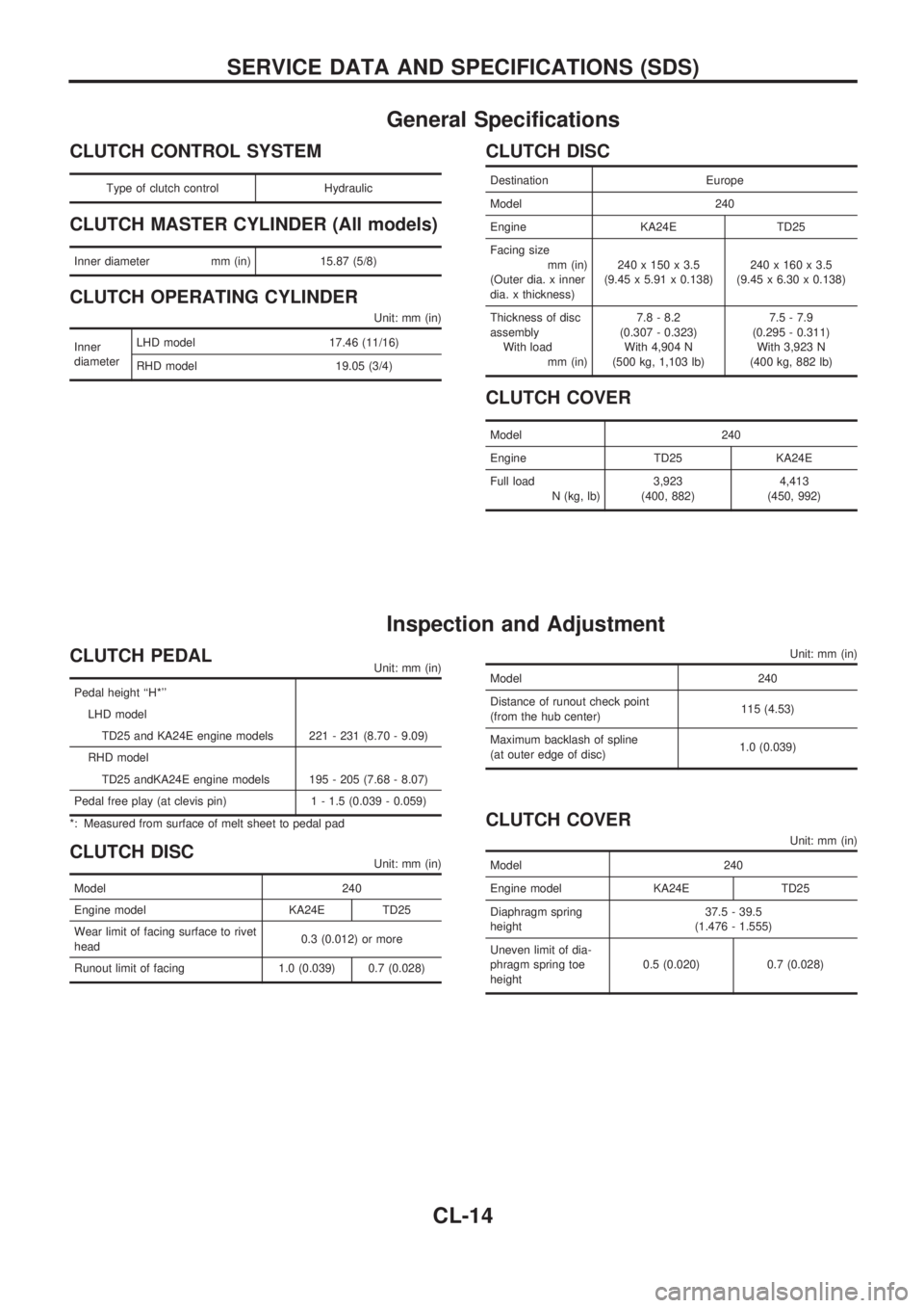
General Specifications
CLUTCH CONTROL SYSTEM
Type of clutch control Hydraulic
CLUTCH MASTER CYLINDER (All models)
Inner diameter mm (in) 15.87 (5/8)
CLUTCH OPERATING CYLINDER
Unit: mm (in)
Inner
diameterLHD model 17.46 (11/16)
RHD model 19.05 (3/4)
CLUTCH DISC
Destination Europe
Model 240
Engine KA24E TD25
Facing size
mm (in)
(Outer dia. x inner
dia. x thickness)240 x 150 x 3.5
(9.45 x 5.91 x 0.138)240 x 160 x 3.5
(9.45 x 6.30 x 0.138)
Thickness of disc
assembly
With load
mm (in)7.8 - 8.2
(0.307 - 0.323)
With 4,904 N
(500 kg, 1,103 lb)7.5 - 7.9
(0.295 - 0.311)
With 3,923 N
(400 kg, 882 lb)
CLUTCH COVER
Model 240
Engine TD25 KA24E
Full load
N (kg, lb)3,923
(400, 882)4,413
(450, 992)
Inspection and Adjustment
CLUTCH PEDALUnit: mm (in)
Pedal height ``H*''
LHD model
TD25 and KA24E engine models 221 - 231 (8.70 - 9.09)
RHD model
TD25 andKA24E engine models 195 - 205 (7.68 - 8.07)
Pedal free play (at clevis pin) 1 - 1.5 (0.039 - 0.059)
*: Measured from surface of melt sheet to pedal pad
CLUTCH DISCUnit: mm (in)
Model 240
Engine model KA24E TD25
Wear limit of facing surface to rivet
head0.3 (0.012) or more
Runout limit of facing 1.0 (0.039) 0.7 (0.028)
Unit: mm (in)
Model 240
Distance of runout check point
(from the hub center)115 (4.53)
Maximum backlash of spline
(at outer edge of disc)1.0 (0.039)
CLUTCH COVER
Unit: mm (in)
Model 240
Engine model KA24E TD25
Diaphragm spring
height37.5 - 39.5
(1.476 - 1.555)
Uneven limit of dia-
phragm spring toe
height0.5 (0.020) 0.7 (0.028)
SERVICE DATA AND SPECIFICATIONS (SDS)
CL-14
Page 150 of 1659
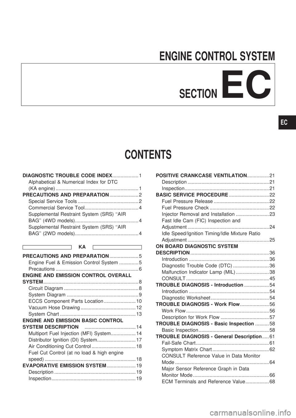
ENGINE CONTROL SYSTEM
SECTION
EC
CONTENTS
DIAGNOSTIC TROUBLE CODE INDEX................... 1
Alphabetical & Numerical Index for DTC
(KA engine) ............................................................ 1
PRECAUTIONS AND PREPARATION..................... 2
Special Service Tools ............................................ 2
Commercial Service Tool....................................... 4
Supplemental Restraint System (SRS) ``AIR
BAG'' (4WD models).............................................. 4
Supplemental Restraint System (SRS) ``AIR
BAG'' (2WD models).............................................. 4
KA
PRECAUTIONS AND PREPARATION..................... 5
Engine Fuel & Emission Control System .............. 5
Precautions ............................................................ 6
ENGINE AND EMISSION CONTROL OVERALL
SYSTEM..................................................................... 8
Circuit Diagram ...................................................... 8
System Diagram .................................................... 9
ECCS Component Parts Location ....................... 10
Vacuum Hose Drawing ........................................ 12
System Chart ....................................................... 13
ENGINE AND EMISSION BASIC CONTROL
SYSTEM DESCRIPTION..................................... 14
Multiport Fuel Injection (MFI) System.................. 14
Distributor Ignition (DI) System............................ 17
Air Conditioning Cut Control ................................ 18
Fuel Cut Control (at no load & high engine
speed) .................................................................. 18
EVAPORATIVE EMISSION SYSTEM..................... 19
Description ........................................................... 19
Inspection ............................................................. 19POSITIVE CRANKCASE VENTILATION................ 21
Description ........................................................... 21
Inspection ............................................................. 21
BASIC SERVICE PROCEDURE............................. 22
Fuel Pressure Release ........................................ 22
Fuel Pressure Check ........................................... 22
Injector Removal and Installation ........................ 23
Fast Idle Cam (FIC) Inspection and
Adjustment ........................................................... 24
Idle Speed/Ignition Timing/Idle Mixture Ratio
Adjustment ........................................................... 25
ON BOARD DIAGNOSTIC SYSTEM
DESCRIPTION......................................................... 36
Introduction .......................................................... 36
Diagnostic Trouble Code (DTC) .......................... 36
Malfunction Indicator Lamp (MIL) ........................ 38
CONSULT ............................................................ 45
TROUBLE DIAGNOSIS - Introduction.................. 54
Introduction .......................................................... 54
Diagnostic Worksheet .......................................... 54
TROUBLE DIAGNOSIS - Work Flow..................... 56
Work Flow ............................................................ 56
Description for Work Flow ................................... 57
TROUBLE DIAGNOSIS - Basic Inspection.......... 58
Basic Inspection ................................................... 58
TROUBLE DIAGNOSIS - General Description..... 61
Fail-Safe Chart ..................................................... 61
Symptom Matrix Chart ......................................... 62
CONSULT Reference Value in Data Monitor
Mode .................................................................... 64
Major Sensor Reference Graph in Data
Monitor Mode ....................................................... 66
ECM Terminals and Reference Value ................. 68
EC