1998 NISSAN PICK-UP wheel
[x] Cancel search: wheelPage 3 of 1659
BRAKE SYSTEM
SECTIONBR
CONTENTS
PRECAUTIONS AND PREPARATION..................... 1
Supplemental Restraint System (SRS) ``AIR
BAG'' (4WD models).............................................. 1
Supplemental Restraint System (SRS) ``AIR
BAG'' (2WD models).............................................. 1
Precautions for Brake System ............................... 1
Special Service Tools ............................................ 2
Commercial Service Tools ..................................... 2
CHECK AND ADJUSTMENT.................................... 3
Checking Brake Fluid Level ................................... 3
Checking Brake Line.............................................. 3
Changing Brake Fluid ............................................ 3
Bleeding Brake System ......................................... 4
BRAKE HYDRAULIC LINE....................................... 5
CONTROL VALVE..................................................... 7
Load Sensing Valve ............................................... 7
BRAKE PEDAL AND BRACKET............................ 10
Removal and Installation ..................................... 10
Inspection ............................................................. 11
Adjustment ........................................................... 11
MASTER CYLINDER............................................... 12
Removal ............................................................... 12
Disassembly ......................................................... 13
Inspection ............................................................. 13
Assembly.............................................................. 13
Installation ............................................................ 14
BRAKE BOOSTER.................................................. 15
On-vehicle Service ............................................... 15
Removal ............................................................... 15
Inspection ............................................................. 15
Installation ............................................................ 16
VACUUM HOSE...................................................... 17
Removal and Installation ..................................... 17Inspection ............................................................. 17
VACUUM PUMP...................................................... 19
Removal and Installation ..................................... 19
Inspection ............................................................. 19
FRONT DISC BRAKE............................................. 21
Pad Replacement ................................................ 21
Removal ............................................................... 22
Disassembly ......................................................... 23
Inspection - Caliper .............................................. 23
Inspection - Rotor ................................................ 23
Assembly.............................................................. 24
Installation ............................................................ 24
Brake Burnishing Procedure ................................ 24
REAR DRUM BRAKE............................................. 26
Removal ............................................................... 27
Inspection - Wheel Cylinder................................. 28
Wheel Cylinder Overhaul ..................................... 28
Inspection - Drum ................................................ 28
Inspection - Lining................................................ 28
Installation ............................................................ 28
PARKING BRAKE CONTROL................................ 30
Removal and Installation ..................................... 31
Inspection ............................................................. 31
Adjustment ........................................................... 31
ANTI-LOCK BRAKE SYSTEM................................ 32
Purpose ................................................................ 32
Operation ............................................................. 32
ABS Hydraulic Circuit .......................................... 32
System Components............................................ 33
System Description .............................................. 33
Removal and Installation ..................................... 35
TROUBLE DIAGNOSES......................................... 38
BR
Page 4 of 1659

How to Perform Trouble Diagnoses for Quick
and Accurate Repair ............................................ 38
Preliminary Check ................................................ 39
Component Parts and Harness Connector
Location................................................................ 40
Schematic/2WD Models....................................... 41
Wiring Diagram - ABS -/2WD LHD Models ......... 42
Wiring Diagram - ABS -/2WD RHD Models ........ 45
Schematic/4WD Models....................................... 48
Wiring Diagram - ABS -/4WD Models ................. 49
Self-diagnosis....................................................... 53
CONSULT ............................................................ 56
CONSULT Inspection Procedure......................... 57
Ground Circuit Check .......................................... 62
TROUBLE DIAGNOSES FOR
SELF-DIAGNOSTIC ITEMS.................................... 63
Diagnostic Procedure 1
(Wheel sensor or rotor)........................................ 63
Diagnostic Procedure 2 (ABS actuator
solenoid valve and solenoid valve relay)............. 65
Diagnostic Procedure 3 (Motor relay or motor) ... 67
Diagnostic Procedure 4 (Low voltage) ................ 69Diagnostic Procedure 5 (G sensor) ..................... 70
Diagnostic Procedure 6 (Control unit) ................. 71
TROUBLE DIAGNOSES FOR SYMPTOMS........... 72
Diagnostic Procedure 7
(ABS works frequently.) ....................................... 72
Diagnostic Procedure 8
(Unexpected pedal action) ................................... 73
Diagnostic Procedure 9
(Long stopping distance) ..................................... 73
Diagnostic Procedure 10
(ABS does not work.)........................................... 74
Diagnostic Procedure 11
(Pedal vibration and noise) .................................. 74
Diagnostic Procedure 12 (Warning lamp does
not come on when ignition switch is turned
ON.)...................................................................... 75
Diagnostic Procedure 13 (Warning lamp stays
on when ignition switch is turned ON.)................ 77
SERVICE DATA AND SPECIFICATIONS (SDS)... 78
General Specifications ......................................... 78
Inspection and Adjustment .................................. 80
When you read wiring diagrams:
lRead GI section, ``HOW TO READ WIRING DIAGRAMS''.
lSee EL section, ``POWER SUPPLY ROUTING'' for power distribution circuit.
When you perform trouble diagnoses, read GI section, ``HOW TO FOLLOW FLOW
CHART IN TROUBLE DIAGNOSES'' and ``HOW TO PERFORM EFFICIENT DIAGNOSIS
FOR AN ELECTRICAL INCIDENT''.
Page 5 of 1659

Supplemental Restraint System (SRS) ``AIR
BAG'' (4WD models)
The Supplemental Restraint System ``AIR BAG'', used along with a seat belt, helps to reduce the risk or
severity of injury to the driver in a frontal collision. The Supplemental Restraint System consists of air bag
module (located in the center of the steering wheel), a diagnosis sensor unit, warning lamp, wiring harness
and spiral cable. Information necessary to service the system safely is included in theRS sectionof this
Service Manual.
WARNING:
lTo avoid rendering the SRS inoperative, which could increase the risk of personal injury or death
in the event of a collision which would result in air bag inflation, all maintenance must be per-
formed by an authorized NISSAN dealer.
lImproper maintenance, including incorrect removal and installation of the SRS, can lead to per-
sonal injury caused by unintentional activation of the system.
lDo not use electrical test equipment on any circuit related to the SRS unless instructed to in this
Service Manual. SRS wiring harnesses are covered with yellow insulation either just before the
harness connectors or for the complete harness, for easy identification.
Supplemental Restraint System (SRS) ``AIR
BAG'' (2WD models)
The Supplemental Restraint System ``AIR BAG'', used along with a seat belt, helps to reduce the risk or
severity of injury to the driver in a frontal collision. The Supplemental Restraint System consists of an air
bag module (located in the center of the steering wheel), a diagnosis sensor unit, warning lamp and spiral
cable. Information necessary to service the system safely is included in theRS sectionof this Service
Manual.
WARNING:
lTo avoid rendering the SRS inoperative, which could increase the risk of personal injury or death
in the event of a collision which would result in air bag inflation, all maintenance must be per-
formed by an authorized NISSAN dealer.
lImproper maintenance, including incorrect removal and installation of the SRS, can lead to per-
sonal injury caused by unintentional activation of the system.
lDo not use electrical test equipment on any circuit related to the SRS.
Precautions for Brake System
lUse brake fluid DOT 3 or DOT 4*1.
lNever reuse drained brake fluid.
lBe careful not to splash brake fluid on painted areas; it
may cause paint damage. If brake fluid is splashed on
painted areas, wash it away with water immediately.
lTo clean master cylinder parts, disc brake caliper parts
or wheel cylinder parts, use clean brake fluid.
lNever use mineral oils such as gasoline or kerosene.
They will ruin rubber parts of the hydraulic system.
lUse flare nut wrench when removing and installing brake
tubes.
lAlways torque brake lines when installing.
WARNING:
lClean brakes with a vacuum dust collector to minimize
the hazard of airborne materials.
*1: Refer to MA section (``Fluids and Lubricants'', ``RECOM-
MENDED FLUIDS AND LUBRICANTS'').
SBR820BA
PRECAUTIONS AND PREPARATION
BR-1
Page 15 of 1659
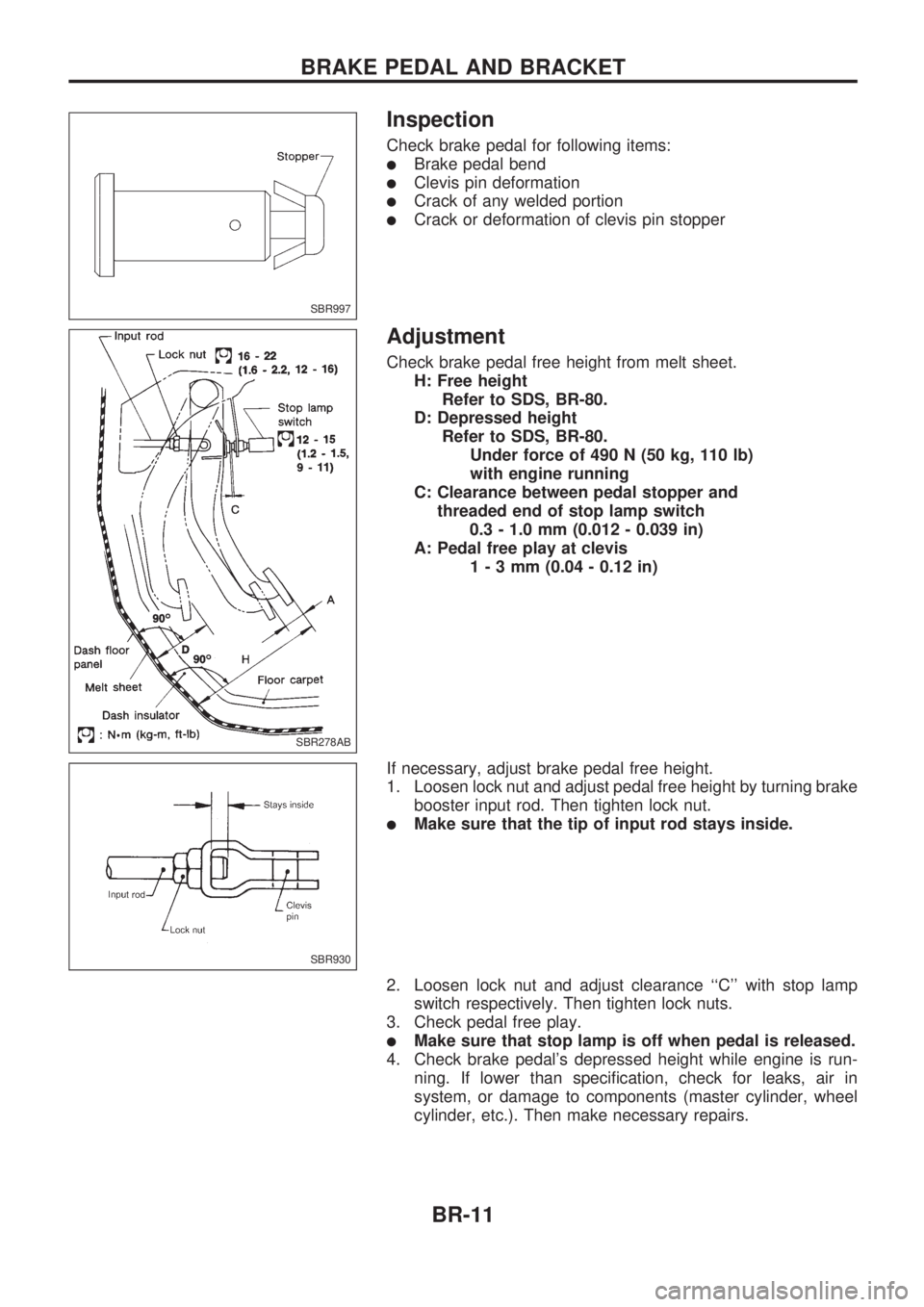
Inspection
Check brake pedal for following items:
lBrake pedal bend
lClevis pin deformation
lCrack of any welded portion
lCrack or deformation of clevis pin stopper
Adjustment
Check brake pedal free height from melt sheet.
H: Free height
Refer to SDS, BR-80.
D: Depressed height
Refer to SDS, BR-80.
Under force of 490 N (50 kg, 110 lb)
with engine running
C: Clearance between pedal stopper and
threaded end of stop lamp switch
0.3 - 1.0 mm (0.012 - 0.039 in)
A: Pedal free play at clevis
1-3mm(0.04 - 0.12 in)
If necessary, adjust brake pedal free height.
1. Loosen lock nut and adjust pedal free height by turning brake
booster input rod. Then tighten lock nut.
lMake sure that the tip of input rod stays inside.
2. Loosen lock nut and adjust clearance ``C'' with stop lamp
switch respectively. Then tighten lock nuts.
3. Check pedal free play.
lMake sure that stop lamp is off when pedal is released.
4. Check brake pedal's depressed height while engine is run-
ning. If lower than specification, check for leaks, air in
system, or damage to components (master cylinder, wheel
cylinder, etc.). Then make necessary repairs.
SBR997
SBR278AB
SBR930
BRAKE PEDAL AND BRACKET
BR-11
Page 27 of 1659
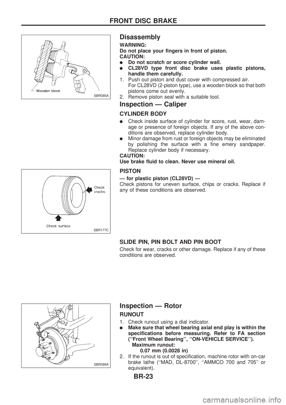
Disassembly
WARNING:
Do not place your fingers in front of piston.
CAUTION:
lDo not scratch or score cylinder wall.
lCL28VD type front disc brake uses plastic pistons,
handle them carefully.
1. Push out piston and dust cover with compressed air.
For CL28VD (2-piston type), use a wooden block so that both
pistons come out evenly.
2. Remove piston seal with a suitable tool.
Inspection Ð Caliper
CYLINDER BODY
lCheck inside surface of cylinder for score, rust, wear, dam-
age or presence of foreign objects. If any of the above con-
ditions are observed, replace cylinder body.
lMinor damage from rust or foreign objects may be eliminated
by polishing the surface with a fine emery sandpaper.
Replace cylinder body if necessary.
CAUTION:
Use brake fluid to clean. Never use mineral oil.
PISTON
Ð for plastic piston (CL28VD) Ð
Check pistons for uneven surface, chips or cracks. Replace if
any of these conditions are observed.
SLIDE PIN, PIN BOLT AND PIN BOOT
Check for wear, cracks or other damage. Replace if any of these
conditions are observed.
Inspection Ð Rotor
RUNOUT
1. Check runout using a dial indicator.
lMake sure that wheel bearing axial end play is within the
specifications before measuring. Refer to FA section
(``Front Wheel Bearing'', ``ON-VEHICLE SERVICE'').
Maximum runout:
0.07 mm (0.0028 in)
2. If the runout is out of specification, machine rotor with on-car
brake lathe (``MAD, DL-8700'', ``AMMCO 700 and 705'' or
equivalent).
SBR085A
SBR177C
SBR089A
FRONT DISC BRAKE
BR-23
Page 31 of 1659
Removal
WARNING:
Clean brake lining with a vacuum dust collector to minimize
the hazard of airborne materials.
CAUTION:
Make sure parking brake lever is completely released.
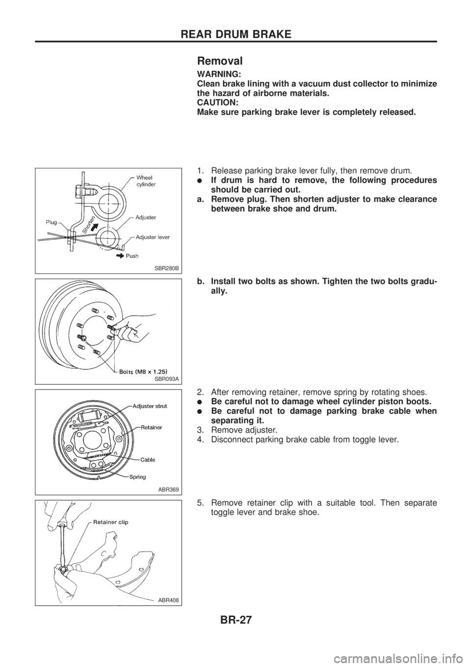
1. Release parking brake lever fully, then remove drum.
lIf drum is hard to remove, the following procedures
should be carried out.
a. Remove plug. Then shorten adjuster to make clearance
between brake shoe and drum.
b. Install two bolts as shown. Tighten the two bolts gradu-
ally.
2. After removing retainer, remove spring by rotating shoes.
lBe careful not to damage wheel cylinder piston boots.
lBe careful not to damage parking brake cable when
separating it.
3. Remove adjuster.
4. Disconnect parking brake cable from toggle lever.
5. Remove retainer clip with a suitable tool. Then separate
toggle lever and brake shoe.
SBR280B
SBR093A
ABR369
ABR408
REAR DRUM BRAKE
BR-27
Page 32 of 1659
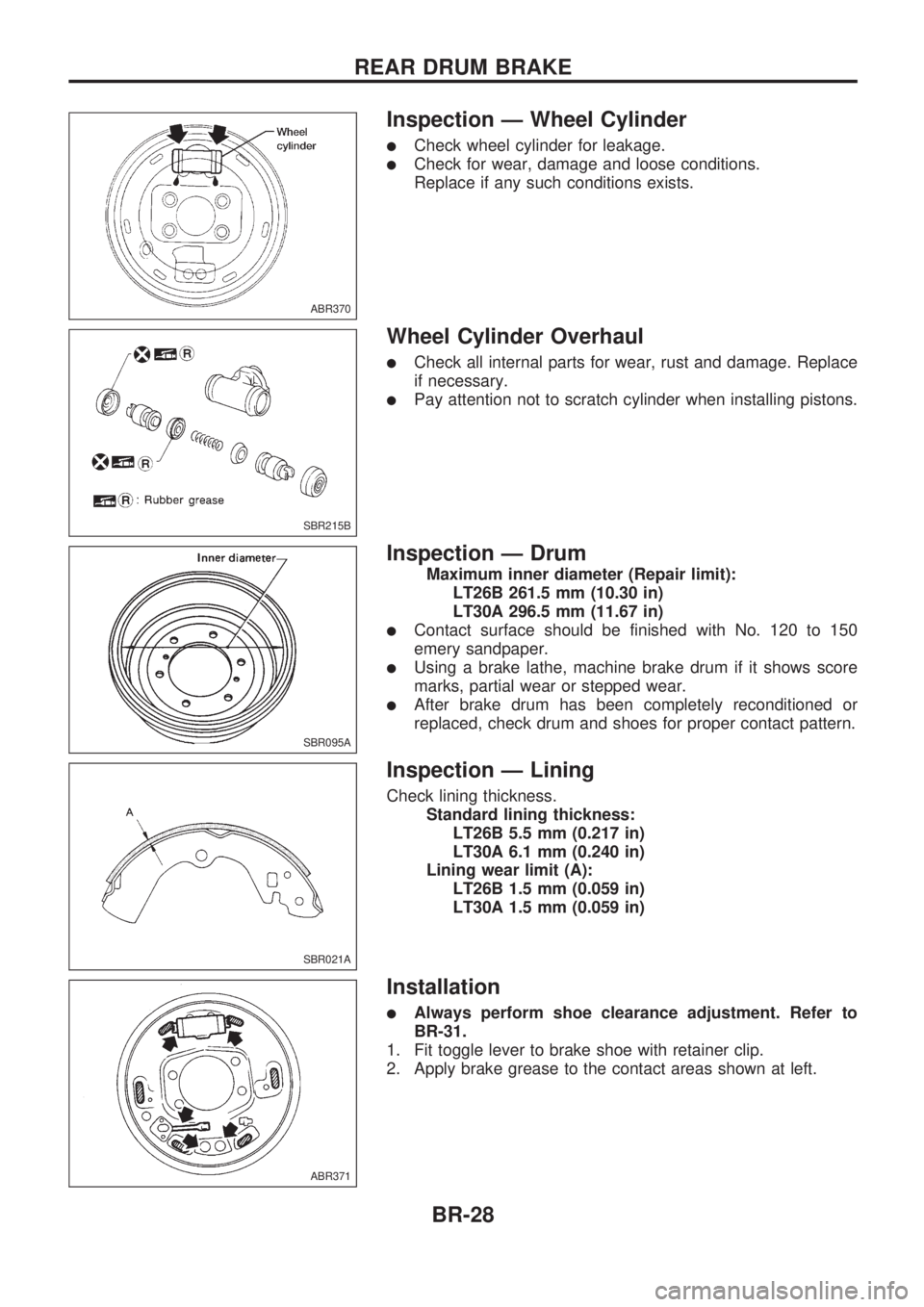
Inspection Ð Wheel Cylinder
lCheck wheel cylinder for leakage.
lCheck for wear, damage and loose conditions.
Replace if any such conditions exists.
Wheel Cylinder Overhaul
lCheck all internal parts for wear, rust and damage. Replace
if necessary.
lPay attention not to scratch cylinder when installing pistons.
Inspection Ð Drum
Maximum inner diameter (Repair limit):
LT26B 261.5 mm (10.30 in)
LT30A 296.5 mm (11.67 in)
lContact surface should be finished with No. 120 to 150
emery sandpaper.
lUsing a brake lathe, machine brake drum if it shows score
marks, partial wear or stepped wear.
lAfter brake drum has been completely reconditioned or
replaced, check drum and shoes for proper contact pattern.
Inspection Ð Lining
Check lining thickness.
Standard lining thickness:
LT26B 5.5 mm (0.217 in)
LT30A 6.1 mm (0.240 in)
Lining wear limit (A):
LT26B 1.5 mm (0.059 in)
LT30A 1.5 mm (0.059 in)
Installation
lAlways perform shoe clearance adjustment. Refer to
BR-31.
1. Fit toggle lever to brake shoe with retainer clip.
2. Apply brake grease to the contact areas shown at left.
ABR370
SBR215B
SBR095A
SBR021A
ABR371
REAR DRUM BRAKE
BR-28
Page 33 of 1659
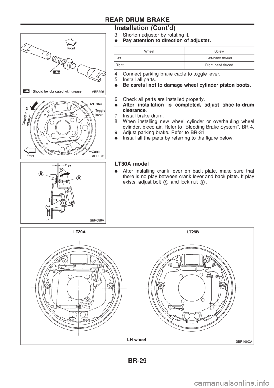
3. Shorten adjuster by rotating it.
lPay attention to direction of adjuster.
Wheel Screw
Left Left-hand thread
Right Right-hand thread
4. Connect parking brake cable to toggle lever.
5. Install all parts.
lBe careful not to damage wheel cylinder piston boots.
6. Check all parts are installed properly.
lAfter installation is completed, adjust shoe-to-drum
clearance.
7. Install brake drum.
8. When installing new wheel cylinder or overhauling wheel
cylinder, bleed air. Refer to ``Bleeding Brake System'', BR-4.
9. Adjust parking brake. Refer to BR-31.
lInstall all the parts by referring to the figure below.
LT30A model
lAfter installing crank lever on back plate, make sure that
there is no play between crank lever and back plate. If play
exists, adjust bolt
VAand lock nutVB.
ABR396
ABR372
SBR099A
SBR100CA
REAR DRUM BRAKE
Installation (Cont'd)
BR-29