Page 650 of 1659
Tool number
Tool nameDescriptionEngine application
KA TD
V1ED19601000
Compression gauge
V2ED19600600
Compression gauge
adapter (for glow
plug hole)
V3ED19600700
Compression gauge
adapter (for injector
hole)
V4ED19600800
Compression gauge
adapter (Useless)
NT625
Checking compression
pressure
ÐX
KV10106001*
Oil filter wrench
NT690
Removing oil filter
ÐX
KV10105800*
Chain stopper
NT010
XÐ
V1KV11101110
Valve seat remover
V2KV11103610
Adapter (Intake)
V3KV11103620
Adapter (Exhaust)
NT251A
Removing valve seat
ÐX
V1ST15243000
Valve seat drift
V2KV11103810
Adapter (Intake)
V3KV11103820
Adapter (Exhaust)
NT252A
Installing valve seat
ÐX
PREPARATION
Special Service Tools (Cont'd)
EM-5
Page 655 of 1659

Measurement of Compression Pressure
1. Warm up engine.
2. Turn ignition switch OFF.
3. Release fuel pressure.
Refer to EC section (``Fuel Pressure Release'', ``BASIC SER-
VICE PROCEDURE'').
4. Remove all spark plugs.
5. Disconnect distributor center cable.
6. Attach a compression tester to No. 1 cylinder.
7. Depress accelerator pedal fully to keep throttle valve wide
open.
8. Crank engine and record highest gauge indication.
9. Repeat the measurement on each cylinder.
lAlways use a fully-charged battery to obtain specified
engine speed.
Compression pressure:
kPa (bar, kg/cm
2, psi)/rpm
Standard
1,324 (13.24, 13.5, 192)/300
Minimum
981 (9.8, 10, 142)/300
Difference limit between cylinders
98 (0.98, 1.0, 14)/300
10. If compression in one or more cylinders is low:
a. Pour a small amount of engine oil into cylinders through
spark plug holes.
b. Retest compression.
lIf adding oil helps compression, piston rings may be
worn or damaged. If so, replace piston rings after check-
ing piston.
lIf pressure stays low, a valve may be sticking or seating
improperly. Inspect and repair valve and valve seat.
(Refer to SDS.) If valve or valve seat is damaged
excessively, replace them.
lIf compression stays low in two cylinders that are next
to each other:
a. The cylinder head gasket may be leaking, or
b. Both cylinders may have valve component damage.
Inspect and repair as necessary.
SEM113B
COMPRESSION PRESSUREKA
EM-10
Page 662 of 1659
Inspection
lCheck for cracks and excessive wear at roller links.
Replace chain if necessary.
Installation
1. Install crankshaft sprocket, oil pump drive gear and oil
thrower.
lMake sure that mating marks on crankshaft sprocket
face front of engine.
2. Position crankshaft so that No. 1 piston is set at TDC (Key-
way at 12 o'clock) fit timing chain to crankshaft sprocket so
that mating mark is in line with mating mark on crankshaft
sprocket.
3. Temporarily install cylinder head with new gasket. Position
camshaft so that keyway is set at 12 o'clock.
lSet timing chain by aligning its mating marks with those
of crankshaft sprocket and camshaft sprocket.
SEM204C
SEM205C
SEM589F
TIMING CHAINKA
EM-17
Page 680 of 1659
3. Set chain on camshaft sprocket by aligning each mating
mark. Then install camshaft sprocket to camshaft.
4. Tighten camshaft sprocket bolt.
5. Install rubber plugs. Refer to TIMING CHAIN, EM-21.
6. Check hydraulic valve lifter.
a. Push hydraulic valve lifter forcefully with your finger.
lBe sure to check it with rocker arm in its free position.
b. If valve lifter moves more than 1 mm (0.04 in), air may be
inside of it.
c. Bleed air off by running engine at 1,000 rpm under no-load
for about 20 minutes.
d. If hydraulic valve lifters are still noisy, replace them and bleed
air off again in the same manner as in step c.
7. Install rocker cover. Refer to TIMING CHAIN, EM-21.
lBe sure to avoid interference between rocker cover and
rocker arm.
8. Install intake and exhaust manifolds. Refer to ``OUTER COM-
PONENT PARTS'', EM-9.
SEM612F
SEM592F
SEM275C
CYLINDER HEADKA
Installation (Cont'd)
EM-35
Page 704 of 1659

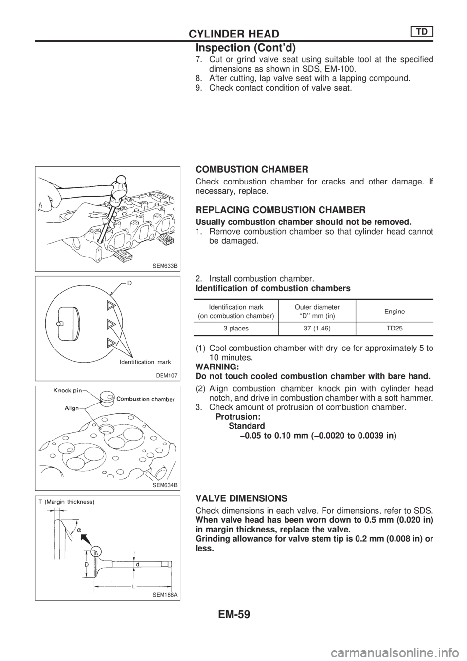
7. Cut or grind valve seat using suitable tool at the specified
dimensions as shown in SDS, EM-100.
8. After cutting, lap valve seat with a lapping compound.
9. Check contact condition of valve seat.
COMBUSTION CHAMBER
Check combustion chamber for cracks and other damage. If
necessary, replace.
REPLACING COMBUSTION CHAMBER
Usually combustion chamber should not be removed.
1. Remove combustion chamber so that cylinder head cannot
be damaged.
2. Install combustion chamber.
Identification of combustion chambers
Identification mark
(on combustion chamber)Outer diameter
``D'' mm (in)Engine
3 places 37 (1.46) TD25
(1) Cool combustion chamber with dry ice for approximately 5 to
10 minutes.
WARNING:
Do not touch cooled combustion chamber with bare hand.
(2) Align combustion chamber knock pin with cylinder head
notch, and drive in combustion chamber with a soft hammer.
3. Check amount of protrusion of combustion chamber.
Protrusion:
Standard
þ0.05 to 0.10 mm (þ0.0020 to 0.0039 in)
VALVE DIMENSIONS
Check dimensions in each valve. For dimensions, refer to SDS.
When valve head has been worn down to 0.5 mm (0.020 in)
in margin thickness, replace the valve.
Grinding allowance for valve stem tip is 0.2 mm (0.008 in) or
less.
SEM633B
DEM107
.
SEM634B
SEM188A
CYLINDER HEADTD
Inspection (Cont'd)
EM-59
Page 709 of 1659

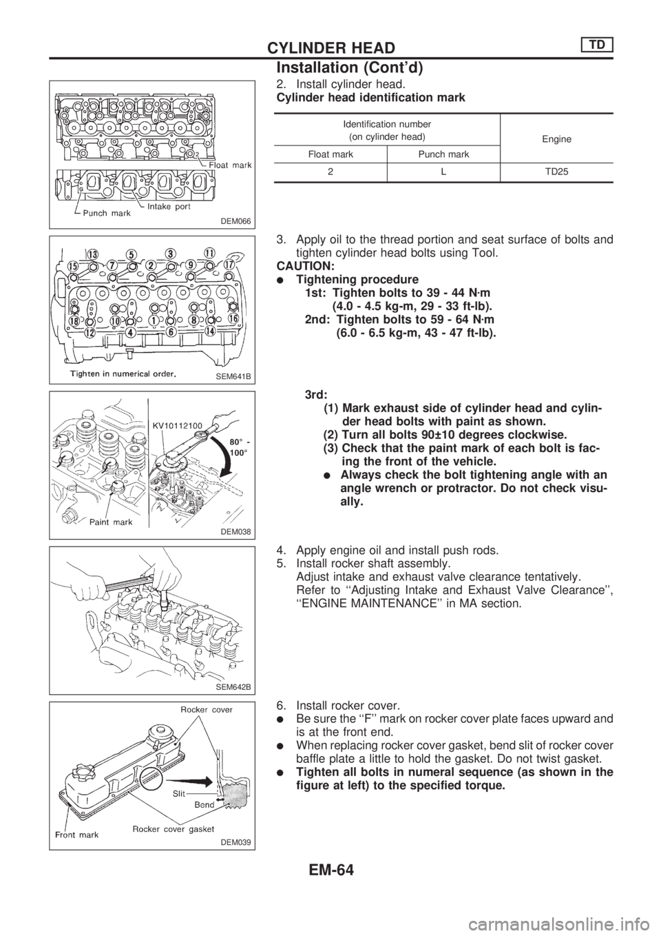
2. Install cylinder head.
Cylinder head identification mark
Identification number
(on cylinder head)
Engine
Float mark Punch mark
2 L TD25
3. Apply oil to the thread portion and seat surface of bolts and
tighten cylinder head bolts using Tool.
CAUTION:
lTightening procedure
1st: Tighten bolts to 39 - 44 Nzm
(4.0 - 4.5 kg-m, 29 - 33 ft-lb).
2nd: Tighten bolts to 59 - 64 Nzm
(6.0 - 6.5 kg-m, 43 - 47 ft-lb).
3rd:
(1) Mark exhaust side of cylinder head and cylin-
der head bolts with paint as shown.
(2) Turn all bolts 90 10 degrees clockwise.
(3) Check that the paint mark of each bolt is fac-
ing the front of the vehicle.
lAlways check the bolt tightening angle with an
angle wrench or protractor. Do not check visu-
ally.
4. Apply engine oil and install push rods.
5. Install rocker shaft assembly.
Adjust intake and exhaust valve clearance tentatively.
Refer to ``Adjusting Intake and Exhaust Valve Clearance'',
``ENGINE MAINTENANCE'' in MA section.
6. Install rocker cover.
lBe sure the ``F'' mark on rocker cover plate faces upward and
is at the front end.
lWhen replacing rocker cover gasket, bend slit of rocker cover
baffle plate a little to hold the gasket. Do not twist gasket.
lTighten all bolts in numeral sequence (as shown in the
figure at left) to the specified torque.
DEM066
SEM641B
DEM038
SEM642B
DEM039
CYLINDER HEADTD
Installation (Cont'd)
EM-64
Page 720 of 1659
2. Check for scratches or seizure. If seizure is found, replace
cylinder liner.
3. Check amount of projection of cylinder liner.
Cylinder liner projection:
Standard
0.02 - 0.09 mm (0.0008 - 0.0035 in)
Deviation of each cylinder:
Less than 0.05 mm (0.0020 in)
CYLINDER LINER
Replacement
1. Remove cylinder liner with Tool.
2. Install cylinder liner with Tool.
3. Check amount of projection of cylinder liner.
PISTON TO CYLINDER WALL CLEARANCE
1. Measure piston and cylinder bore diameter.
Piston diameter ``A'':
Refer to SDS, EM-103.
Measuring point ``a''
(Distance from the top): mm (in)
70 (2.76)
2. Check that piston clearance is within the specification.
Piston clearance:
0.05 - 0.07 mm (0.0020 - 0.0028 in)
SEM920A
SEM849
SEM659B
SEM660B
ENGINE OVERHAULTD
Inspection and Replacement (Cont'd)
EM-75
Page 721 of 1659

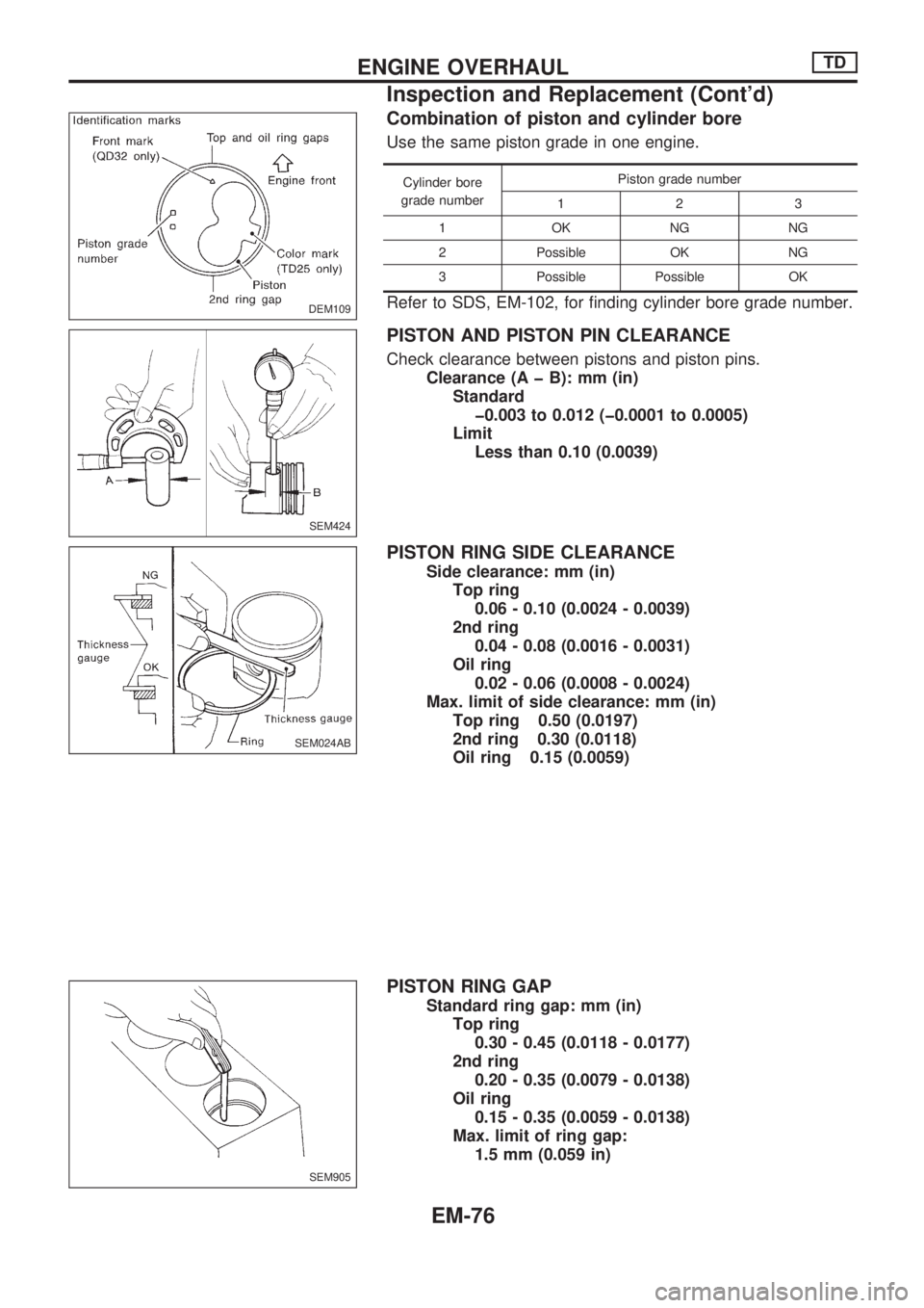
Combination of piston and cylinder bore
Use the same piston grade in one engine.
Cylinder bore
grade numberPiston grade number
123
1OKNGNG
2 Possible OK NG
3 Possible Possible OK
Refer to SDS, EM-102, for finding cylinder bore grade number.
PISTON AND PISTON PIN CLEARANCE
Check clearance between pistons and piston pins.
Clearance (A þ B): mm (in)
Standard
þ0.003 to 0.012 (þ0.0001 to 0.0005)
Limit
Less than 0.10 (0.0039)
PISTON RING SIDE CLEARANCE
Side clearance: mm (in)
Top ring
0.06 - 0.10 (0.0024 - 0.0039)
2nd ring
0.04 - 0.08 (0.0016 - 0.0031)
Oil ring
0.02 - 0.06 (0.0008 - 0.0024)
Max. limit of side clearance: mm (in)
Top ring 0.50 (0.0197)
2nd ring 0.30 (0.0118)
Oil ring 0.15 (0.0059)
PISTON RING GAP
Standard ring gap: mm (in)
Top ring
0.30 - 0.45 (0.0118 - 0.0177)
2nd ring
0.20 - 0.35 (0.0079 - 0.0138)
Oil ring
0.15 - 0.35 (0.0059 - 0.0138)
Max. limit of ring gap:
1.5 mm (0.059 in)
DEM109
SEM424
SEM024AB
SEM905
ENGINE OVERHAULTD
Inspection and Replacement (Cont'd)
EM-76