1998 NISSAN PICK-UP check engine
[x] Cancel search: check enginePage 893 of 1659
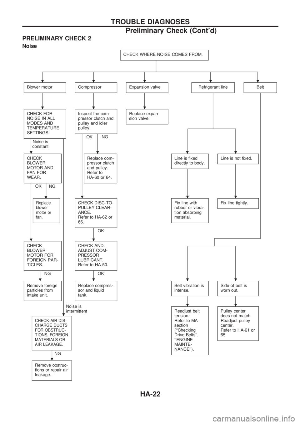
PRELIMINARY CHECK 2
Noise
CHECK WHERE NOISE COMES FROM.
Blower motorCompressorExpansion valveRefrigerant lineBelt
CHECK FOR
NOISE IN ALL
MODES AND
TEMPERATURE
SETTINGS.
Noise is
constant
.
Inspect the com-
pressor clutch and
pulley and idler
pulley.
OK NGReplace expan-
sion valve.
CHECK
BLOWER
MOTOR AND
FAN FOR
WEAR.
OK
.
NGReplace com-
pressor clutch
and pulley.
Refer to
HA-60 or 64.
Line is fixed
directly to body.Line is not fixed.
Replace
blower
motor or
fan.CHECK DISC-TO-
PULLEY CLEAR-
ANCE.
Refer to HA-62 or
66.
OKFix line with
rubber or vibra-
tion absorbing
material.
Fix line tightly.
CHECK
BLOWER
MOTOR FOR
FOREIGN PAR-
TICLES.
NGCHECK AND
ADJUST COM-
PRESSOR
LUBRICANT.
Refer to HA-50.OK
Remove foreign
particles from
intake unit.
Replace compres-
sor and liquid
tank.Belt vibration is
intense.Side of belt is
worn out.
Noise is
intermittent
CHECK AIR DIS-
CHARGE DUCTS
FOR OBSTRUC-
TIONS, FOREIGN
MATERIALS OR
AIR LEAKAGE.
.
NGReadjust belt
tension.
Refer to MA
section
(``Checking
Drive Belts'',
``ENGINE
MAINTE-
NANCE'').
Pulley center
does not match.
Readjust pulley
center.
Refer to HA-61 or
65.
Remove obstruc-
tions or repair air
leakage.
.....
...
....
...
..
....
..
TROUBLE DIAGNOSES
Preliminary Check (Cont'd)
HA-22
Page 894 of 1659
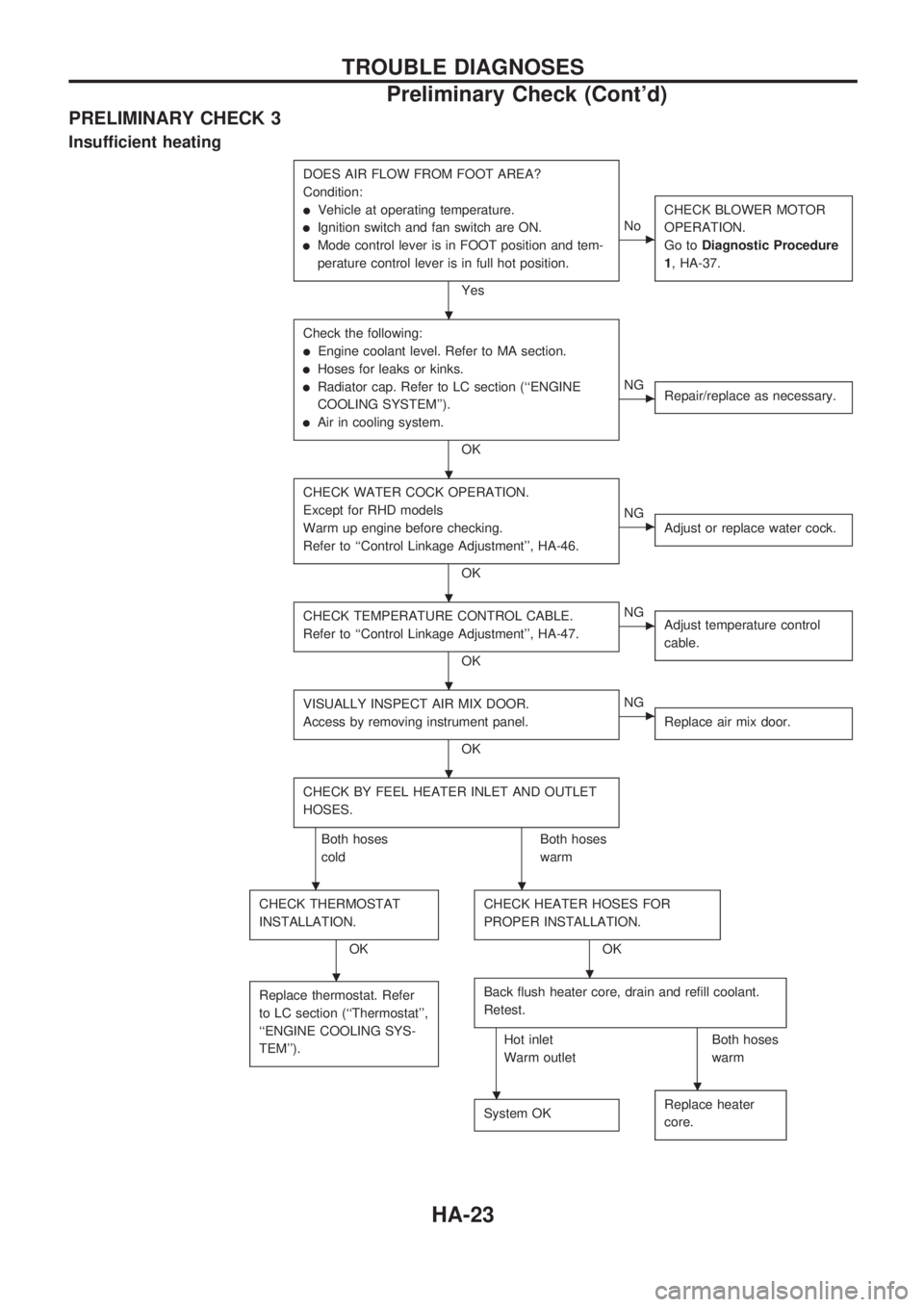
PRELIMINARY CHECK 3
Insufficient heating
DOES AIR FLOW FROM FOOT AREA?
Condition:
lVehicle at operating temperature.
lIgnition switch and fan switch are ON.
lMode control lever is in FOOT position and tem-
perature control lever is in full hot position.
Yes
cNoCHECK BLOWER MOTOR
OPERATION.
Go toDiagnostic Procedure
1, HA-37.
Check the following:
lEngine coolant level. Refer to MA section.
lHoses for leaks or kinks.
lRadiator cap. Refer to LC section (``ENGINE
COOLING SYSTEM'').
lAir in cooling system.
OK
cNG
Repair/replace as necessary.
CHECK WATER COCK OPERATION.
Except for RHD models
Warm up engine before checking.
Refer to ``Control Linkage Adjustment'', HA-46.
OK
cNG
Adjust or replace water cock.
CHECK TEMPERATURE CONTROL CABLE.
Refer to ``Control Linkage Adjustment'', HA-47.
OK
cNG
Adjust temperature control
cable.
VISUALLY INSPECT AIR MIX DOOR.
Access by removing instrument panel.
OK
cNG
Replace air mix door.
CHECK BY FEEL HEATER INLET AND OUTLET
HOSES.
Both hoses
coldBoth hoses
warm
CHECK THERMOSTAT
INSTALLATION.
OKCHECK HEATER HOSES FOR
PROPER INSTALLATION.OK
Replace thermostat. Refer
to LC section (``Thermostat'',
``ENGINE COOLING SYS-
TEM'').
Back flush heater core, drain and refill coolant.
Retest.
Hot inlet
Warm outletBoth hoses
warm
System OK
Replace heater
core.
.
.
.
.
.
..
..
..
TROUBLE DIAGNOSES
Preliminary Check (Cont'd)
HA-23
Page 896 of 1659
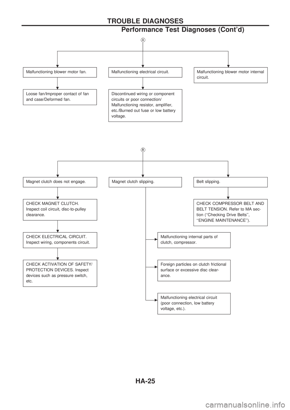
VA
Malfunctioning blower motor fan.Malfunctioning electrical circuit.Malfunctioning blower motor internal
circuit.
Loose fan/Improper contact of fan
and case/Deformed fan.Discontinued wiring or component
circuits or poor connection/
Malfunctioning resistor, amplifier,
etc./Burned out fuse or low battery
voltage.
VB
Magnet clutch does not engage.Magnet clutch slipping.Belt slipping.
CHECK MAGNET CLUTCH.
Inspect coil circuit, disc-to-pulley
clearance.CHECK COMPRESSOR BELT AND
BELT TENSION. Refer to MA sec-
tion (``Checking Drive Belts'',
``ENGINE MAINTENANCE'').
CHECK ELECTRICAL CIRCUIT.
Inspect wiring, components circuit.cMalfunctioning internal parts of
clutch, compressor.
CHECK ACTIVATION OF SAFETY/
PROTECTION DEVICES. Inspect
devices such as pressure switch,
etc.cForeign particles on clutch frictional
surface or excessive disc clear-
ance.
cMalfunctioning electrical circuit
(poor connection, low battery
voltage, etc.).
...
..
...
..
.
.
TROUBLE DIAGNOSES
Performance Test Diagnoses (Cont'd)
HA-25
Page 898 of 1659
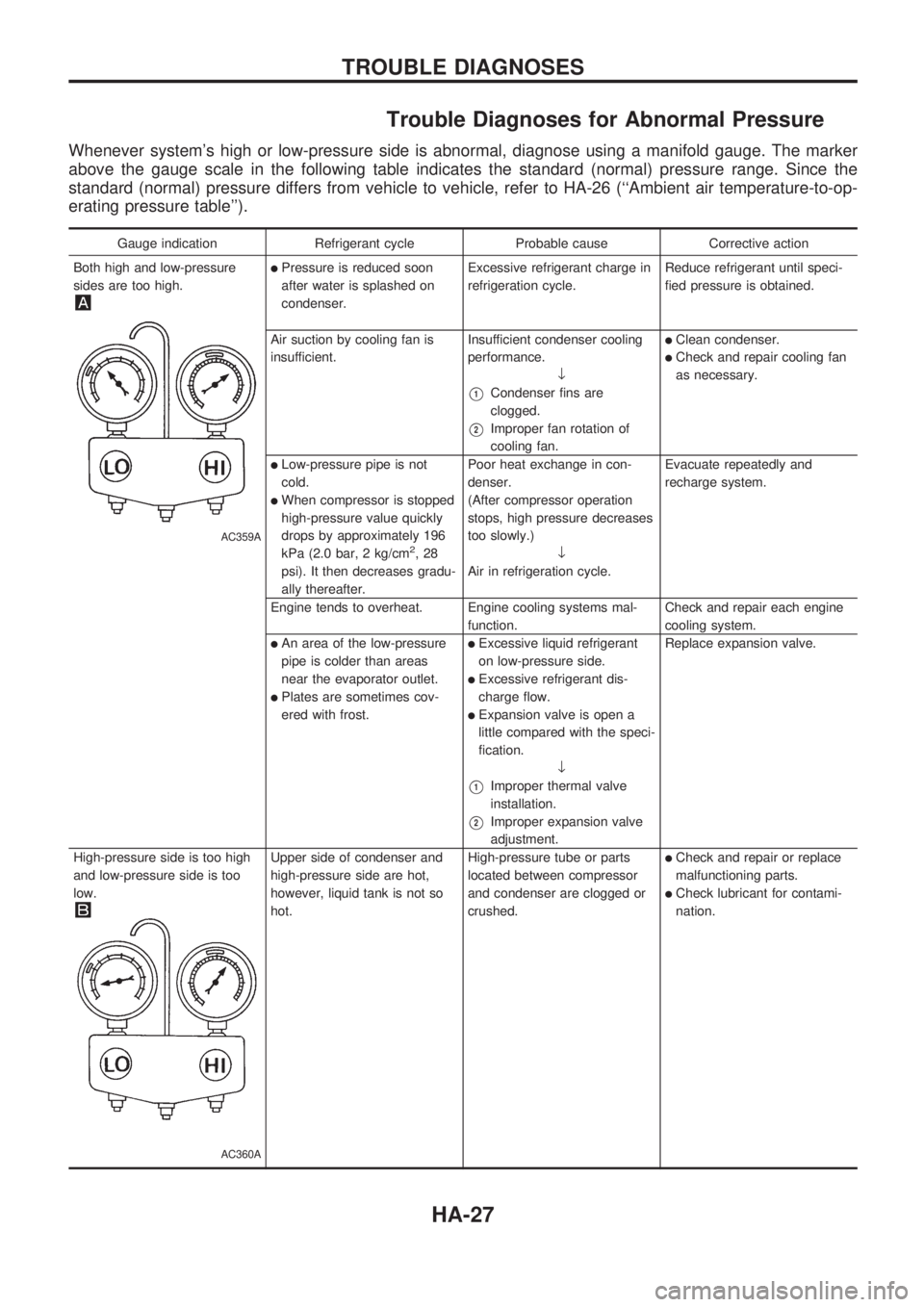
Trouble Diagnoses for Abnormal Pressure
Whenever system's high or low-pressure side is abnormal, diagnose using a manifold gauge. The marker
above the gauge scale in the following table indicates the standard (normal) pressure range. Since the
standard (normal) pressure differs from vehicle to vehicle, refer to HA-26 (``Ambient air temperature-to-op-
erating pressure table'').
Gauge indication Refrigerant cycle Probable cause Corrective action
Both high and low-pressure
sides are too high.
AC359A
lPressure is reduced soon
after water is splashed on
condenser.Excessive refrigerant charge in
refrigeration cycle.Reduce refrigerant until speci-
fied pressure is obtained.
Air suction by cooling fan is
insufficient.Insufficient condenser cooling
performance.
¯
V1Condenser fins are
clogged.
V2Improper fan rotation of
cooling fan.
lClean condenser.
lCheck and repair cooling fan
as necessary.
lLow-pressure pipe is not
cold.
lWhen compressor is stopped
high-pressure value quickly
drops by approximately 196
kPa (2.0 bar, 2 kg/cm
2,28
psi). It then decreases gradu-
ally thereafter.Poor heat exchange in con-
denser.
(After compressor operation
stops, high pressure decreases
too slowly.)
¯
Air in refrigeration cycle.Evacuate repeatedly and
recharge system.
Engine tends to overheat. Engine cooling systems mal-
function.Check and repair each engine
cooling system.
lAn area of the low-pressure
pipe is colder than areas
near the evaporator outlet.
lPlates are sometimes cov-
ered with frost.
lExcessive liquid refrigerant
on low-pressure side.
lExcessive refrigerant dis-
charge flow.
lExpansion valve is open a
little compared with the speci-
fication.
¯
V1Improper thermal valve
installation.
V2Improper expansion valve
adjustment.Replace expansion valve.
High-pressure side is too high
and low-pressure side is too
low.
AC360A
Upper side of condenser and
high-pressure side are hot,
however, liquid tank is not so
hot.High-pressure tube or parts
located between compressor
and condenser are clogged or
crushed.lCheck and repair or replace
malfunctioning parts.
lCheck lubricant for contami-
nation.
TROUBLE DIAGNOSES
HA-27
Page 910 of 1659

Diagnostic Procedure 2
EXCEPT FOR KA ENGINE MODELS
SYMPTOM: Magnet clutch does not engage when A/C
switch and fan switch are ON.
lPerform PRELIMINARY CHECK 1 before referring to the
following flow chart.
CHECK POWER SUPPLY FOR COM-
PRESSOR.
Disconnect compressor harness connec-
tor.
Do approx. 12 volts exist between com-
pressor harness terminal No.
V1and body
ground?
No
cYes
Check the following.
lMagnet clutch coillThermal protector (Except
for the Middle East)
NG
Replace magnet clutch.
Refer to HA-60.
Note
Check circuit continuity between A/C relay
harness terminal No.
V5and compressor
harness terminal No.
V1.
Continuity should exist.
If OK, check harness for short.
OK
CHECK POWER SUPPLY FOR A/C
RELAY.
Do approx. 12 volts exist between A/C
relay harness terminal No.
V3and body
ground?
Yes
cNo
Check power supply circuit
and 7.5A fuse (No.
21 ,
located in the fuse block).
(Refer to ``POWER SUP-
PLY ROUTING'' in EL sec-
tion and Wiring Diagram.)
CHECK POWER SUPPLY FOR A/C
RELAY.
Do approx. 12 volts exist between A/C
relay harness terminal No.
V1and body
ground?
No
cYes
Check power supply circuit
and 7.5A fuse (No.
21 ,
located in the fuse block).
(Refer to ``POWER SUP-
PLY ROUTING'' in EL sec-
tion and Wiring Diagram.)
CHECK A/C RELAY AFTER DISCON-
NECTING IT.
Refer to HA-44.
OK
cNG
Replace A/C relay.
Reconnect A/C relay.
Note
Check circuit continuity between A/C relay
harness terminal No.
V2and triple-pres-
sure switch harness terminal No.
V4.
Continuity should exist.
If OK, check harness for short.
OK
VA(Go to next page.)
Note:
If the result is NG after checking circuit continuity, repair harness or con-
nector.
RHA325G
RHA748FD
RHA359G
RHA375G
RHA327GA
.
.
.
.
.
.
.
.
TROUBLE DIAGNOSES
HA-39
Page 912 of 1659

FOR KA ENGINE MODELS
SYMPTOM: Magnet clutch does not engage when A/C
switch and fan switch are ON.
lPerform PRELIMINARY CHECK 1 before referring to the
following flow chart.
CHECK POWER SUPPLY FOR COM-
PRESSOR.
Disconnect compressor harness connec-
tor.
Do approx. 12 volts exist between com-
pressor harness terminal No.
V1and body
ground?
No
cYes
Check the following.
lMagnet clutch coil
lThermal protector
NG
Replace magnet clutch.
Refer to HA-60.
Note
Check circuit continuity between A/C relay
harness terminal No.
V5and compressor
harness terminal No.
V1.
Continuity should exist.
If OK, check harness for short.
OK
CHECK POWER SUPPLY FOR A/C
RELAY.
Do approx. 12 volts exist between A/C
relay harness terminal No.
V3and body
ground?
Yes
cNo
Check power supply circuit
and 7.5A fuse (No.
21 ,
located in the fuse block).
(Refer to ``POWER SUP-
PLY ROUTING'' in EL sec-
tion and Wiring Diagram.)
CHECK POWER SUPPLY FOR A/C
RELAY.
Do approx. 12 volts exist between A/C
relay harness terminal No.
V1and body
ground?
Yes
cNo
Check power supply circuit
and 7.5A fuse (No.
21 ,
located in the fuse block).
(Refer to ``POWER SUP-
PLY ROUTING'' in EL sec-
tion and Wiring Diagram.)
CHECK A/C RELAY AFTER DISCON-
NECTING IT.
Refer to HA-44.
OK
cNG
Replace A/C relay.
Reconnect A/C relay.
VA
(Go to next page.)
Note:
If the result is NG after checking circuit continuity, repair harness or con-
nector.
RHA333G
RHA334G
RHA359G
RHA375G
.
.
.
.
.
.
.
TROUBLE DIAGNOSES
Diagnostic Procedure 2 (Cont'd)
HA-41
Page 919 of 1659
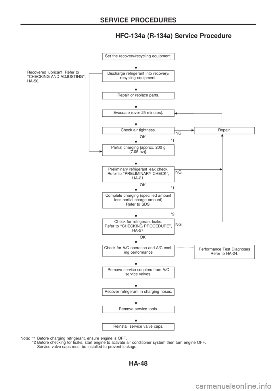
HFC-134a (R-134a) Service Procedure
Set the recovery/recycling equipment.
Recovered lubricant. Refer to
``CHECKING AND ADJUSTING'',
HA-50.
c
Discharge refrigerant into recovery/
recycling equipment.
Repair or replace parts.
Evacuate (over 25 minutes).b
Check air tightness.
OK
*1
cNGRepair.m
Partial charging [approx. 200 g
(7.05 oz)].
Preliminary refrigerant leak check.
Refer to ``PRELIMINARY CHECK'',
HA-21.
OK
*1
cNG
Complete charging (specified amount
less partial charge amount)
Refer to SDS.
*2
Check for refrigerant leaks.
Refer to ``CHECKING PROCEDURE'',
HA-57.
OK
NG
Check for A/C operation and A/C cool-
ing performance..................
Performance Test Diagnoses
Refer to HA-24.
Remove service couplers from A/C
service valves.
Recover refrigerant in charging hoses.
Remove service tools.
Reinstall service valve caps.
Note: *1 Before charging refrigerant, ensure engine is OFF.
*2 Before checking for leaks, start engine to activate air conditioner system then turn engine OFF.
Service valve caps must be installed to prevent leakage.
.
.
.
.
.
.
.
.
.
.
.
.
.
SERVICE PROCEDURES
HA-48
Page 921 of 1659
Maintenance of Lubricant Quantity in
Compressor
The lubricant used to lubricate the compressor circulates through
the system with the refrigerant. Add lubricant to compressor
when replacing any component or after a large gas leakage
occurred. It is important to maintain the specified amount.
If lubricant quantity is not maintained properly, the following mal-
functions may result:
lLack of lubricant: May lead to a seized compressor
lExcessive lubricant: Inadequate cooling (thermal exchange
interference)
LUBRICANT
Name: Nissan A/C System Oil Type R
Part number: KLH00-PAGR0
CHECKING AND ADJUSTING
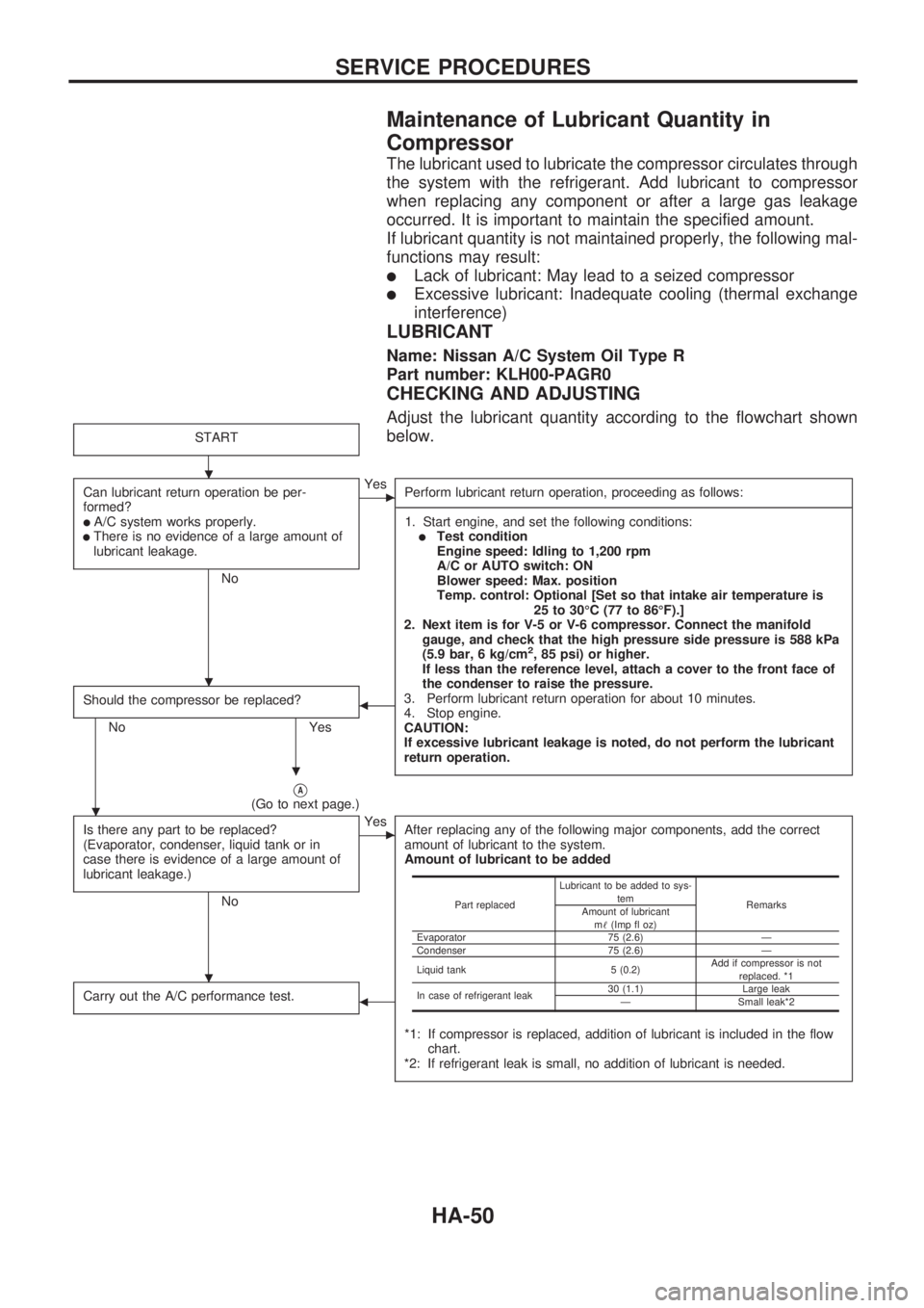
Adjust the lubricant quantity according to the flowchart shown
below.
START
Can lubricant return operation be per-
formed?
lA/C system works properly.lThere is no evidence of a large amount of
lubricant leakage.
No
cYes
Perform lubricant return operation, proceeding as follows:
-----------------------------------------------------------------------------------------------------------------------------------------------------------------------------------------------------------------------------------------------------------------------------------------------------------------------------------------------------------------------------------------------------------------------------------------------------------------------------------------------------------------------------------
1. Start engine, and set the following conditions:
lTest condition
Engine speed: Idling to 1,200 rpm
A/C or AUTO switch: ON
Blower speed: Max. position
Temp. control: Optional [Set so that intake air temperature is
25 to 30ÉC (77 to 86ÉF).]
2. Next item is for V-5 or V-6 compressor. Connect the manifold
gauge, and check that the high pressure side pressure is 588 kPa
(5.9 bar, 6 kg/cm
2, 85 psi) or higher.
If less than the reference level, attach a cover to the front face of
the condenser to raise the pressure.
3. Perform lubricant return operation for about 10 minutes.
4. Stop engine.
CAUTION:
If excessive lubricant leakage is noted, do not perform the lubricant
return operation.
Should the compressor be replaced?
No Yes
b
VA(Go to next page.)
Is there any part to be replaced?
(Evaporator, condenser, liquid tank or in
case there is evidence of a large amount of
lubricant leakage.)
No
cYes
After replacing any of the following major components, add the correct
amount of lubricant to the system.
Amount of lubricant to be added
*1: If compressor is replaced, addition of lubricant is included in the flow
chart.
*2: If refrigerant leak is small, no addition of lubricant is needed.
Carry out the A/C performance test.b
Part replacedLubricant to be added to sys-
tem
Remarks
Amount of lubricant
m!(Imp fl oz)
Evaporator 75 (2.6) Ð
Condenser 75 (2.6) Ð
Liquid tank 5 (0.2)Add if compressor is not
replaced. *1
In case of refrigerant leak30 (1.1) Large leak
Ð Small leak*2
.
.
.
.
.
SERVICE PROCEDURES
HA-50