Page 928 of 1659
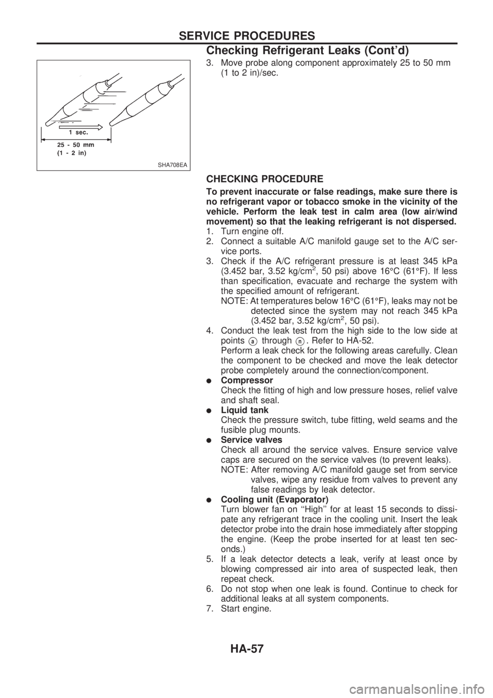
3. Move probe along component approximately 25 to 50 mm
(1 to 2 in)/sec.
CHECKING PROCEDURE
To prevent inaccurate or false readings, make sure there is
no refrigerant vapor or tobacco smoke in the vicinity of the
vehicle. Perform the leak test in calm area (low air/wind
movement) so that the leaking refrigerant is not dispersed.
1. Turn engine off.
2. Connect a suitable A/C manifold gauge set to the A/C ser-
vice ports.
3. Check if the A/C refrigerant pressure is at least 345 kPa
(3.452 bar, 3.52 kg/cm
2, 50 psi) above 16ÉC (61ÉF). If less
than specification, evacuate and recharge the system with
the specified amount of refrigerant.
NOTE: At temperatures below 16ÉC (61ÉF), leaks may not be
detected since the system may not reach 345 kPa
(3.452 bar, 3.52 kg/cm
2, 50 psi).
4. Conduct the leak test from the high side to the low side at
points
VathroughVn. Refer to HA-52.
Perform a leak check for the following areas carefully. Clean
the component to be checked and move the leak detector
probe completely around the connection/component.
lCompressor
Check the fitting of high and low pressure hoses, relief valve
and shaft seal.
lLiquid tank
Check the pressure switch, tube fitting, weld seams and the
fusible plug mounts.
lService valves
Check all around the service valves. Ensure service valve
caps are secured on the service valves (to prevent leaks).
NOTE: After removing A/C manifold gauge set from service
valves, wipe any residue from valves to prevent any
false readings by leak detector.
lCooling unit (Evaporator)
Turn blower fan on ``High'' for at least 15 seconds to dissi-
pate any refrigerant trace in the cooling unit. Insert the leak
detector probe into the drain hose immediately after stopping
the engine. (Keep the probe inserted for at least ten sec-
onds.)
5. If a leak detector detects a leak, verify at least once by
blowing compressed air into area of suspected leak, then
repeat check.
6. Do not stop when one leak is found. Continue to check for
additional leaks at all system components.
7. Start engine.
SHA708EA
SERVICE PROCEDURES
Checking Refrigerant Leaks (Cont'd)
HA-57
Page 929 of 1659
8. Set the heater A/C control as follows:
a. A/C switch ON
b. Face mode
c. Recirculation switch ON
d. Max cold temperature
e. Fan speed high
9. Run engine at 1,500 rpm for at least 2 minutes.
10. Turn engine off and perform leak check again following steps
4 through 6 above.
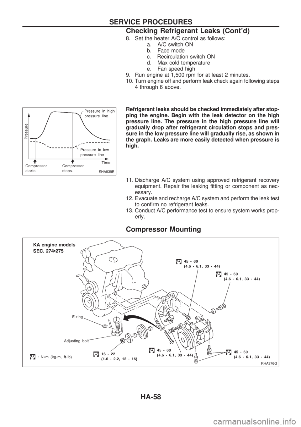
Refrigerant leaks should be checked immediately after stop-
ping the engine. Begin with the leak detector on the high
pressure line. The pressure in the high pressure line will
gradually drop after refrigerant circulation stops and pres-
sure in the low pressure line will gradually rise, as shown in
the graph. Leaks are more easily detected when pressure is
high.
11. Discharge A/C system using approved refrigerant recovery
equipment. Repair the leaking fitting or component as nec-
essary.
12. Evacuate and recharge A/C system and perform the leak test
to confirm no refrigerant leaks.
13. Conduct A/C performance test to ensure system works prop-
erly.
Compressor Mounting
SHA839E
RHA376G
SERVICE PROCEDURES
Checking Refrigerant Leaks (Cont'd)
HA-58
Page 938 of 1659
General Specifications
COMPRESSOR
Model ZEXEL make DKV-14C
Type Vane rotary
Displacement cm
3(cu in)/rev. 140 (8.54)
Direction of rotationClockwise
(Viewed from drive end)
Drive belt A Type
LUBRICANT
Model ZEXEL make DKV-14C
Type KLH00-PAGR0
Capacity m!(lmp fl oz)
Total in system 200 (7.0)
Compressor (Service parts)
charging amount200 (7.0)
Inspection and Adjustment
REFRIGERANT
Type HFC-134a (R-134a)
Capacity kg (lb)0.60 - 0.70
(1.32 - 1.54)
ENGINE IDLING SPEED (When A/C is ON.)
lRefer to EC section.
BELT TENSION
lRefer to MA section (``Checking Drive
Belts'', ``ENGINE MAINTENANCE'').
COMPRESSOR
Model DKS-17CH DKV-14C
Clutch disc-to-pulley
clearance mm (in)0.3 - 0.6
(0.012 - 0.024)0.3 - 0.6
(0.012 - 0.024)
SERVICE DATA AND SPECIFICATIONS (SDS)
HA-67
Page 939 of 1659
ENGINE LUBRICATION &
COOLING SYSTEMS
SECTION
LC
CONTENTS
PRECAUTIONS AND PREPARATION..................... 1
Liquid Gasket Application Procedure .................... 1
Special Service Tools ............................................ 2
KA
ENGINE LUBRICATION SYSTEM............................ 3
Lubrication Circuit .................................................. 3
Oil Pressure Check ................................................ 4
Oil Pump ................................................................ 4
ENGINE COOLING SYSTEM.................................... 6
Cooling Circuit........................................................ 6
System Check ........................................................ 6
Water Pump ........................................................... 7
Thermostat ............................................................. 8
Radiator.................................................................. 9
Cooling Fan (Crankshaft driven).......................... 10
TD
ENGINE LUBRICATION SYSTEM.......................... 12
Lubrication Circuit ................................................ 12
Oil Pressure Check (On-vehicle service) ............ 13
Oil Pump .............................................................. 14
Oil Filter Bracket .................................................. 16
Oil Cooler ............................................................. 17Oil Jet ................................................................... 18
ENGINE COOLING SYSTEM.................................. 19
Cooling Circuit...................................................... 19
Cooling System Inspection .................................. 20
Water Pump and Cooling Fan (Camshaft
driven) .................................................................. 21
Thermostat ........................................................... 23
Radiator................................................................ 24
Refilling Engine Coolant ...................................... 24
ENGINE ROOM FAN MOTOR ELECTRICAL
CIRCUIT................................................................... 25
Wiring Diagram .................................................... 25
Cooling Fan (Motor driven) .................................. 26
Electrical Components Inspection ....................... 26
ENGINE COOLING SYSTEM.................................. 28
Radiator (Aluminum type) .................................... 28
Overheating Cause Analysis ............................... 31
SERVICE DATA AND SPECIFICATIONS (SDS)... 32
Engine Lubrication System (KA).......................... 32
Engine Cooling System (KA) ............................... 32
Engine Lubrication System (TD).......................... 32
Engine Cooling System (TD) ............................... 32
LC
Page 943 of 1659
Oil Pressure Check
WARNING:
lBe careful not to burn yourself, as the engine and oil
may be hot.
lPut gearshift lever in Neutral N position.
1. Check oil level.
2. Remove oil pressure switch.
3. Install pressure gauge.
4. Start engine and warm it up to normal operating temperature.
5. Check oil pressure with engine running under no-load.
Engine speed
rpmApproximate discharge pressure
kPa (bar, kg/cm2, psi)
Idle speed More than 78 (0.78, 0.8, 11)
3,000 412 - 481 (4.12 - 4.81, 4.2 - 4.9, 60 - 70)
lIf difference is extreme, check oil passage and oil pump
for oil leaks.
6. Install oil pressure switch with sealant.
Oil Pump
SLC183A
SLC770A
SLC229B
ENGINE LUBRICATION SYSTEMKA
LC-4
Page 944 of 1659
lAlways replace with new oil seal and gasket.
lWhen removing oil pump, turn crankshaft so that No. 1
piston is at TDC on its compression stroke.
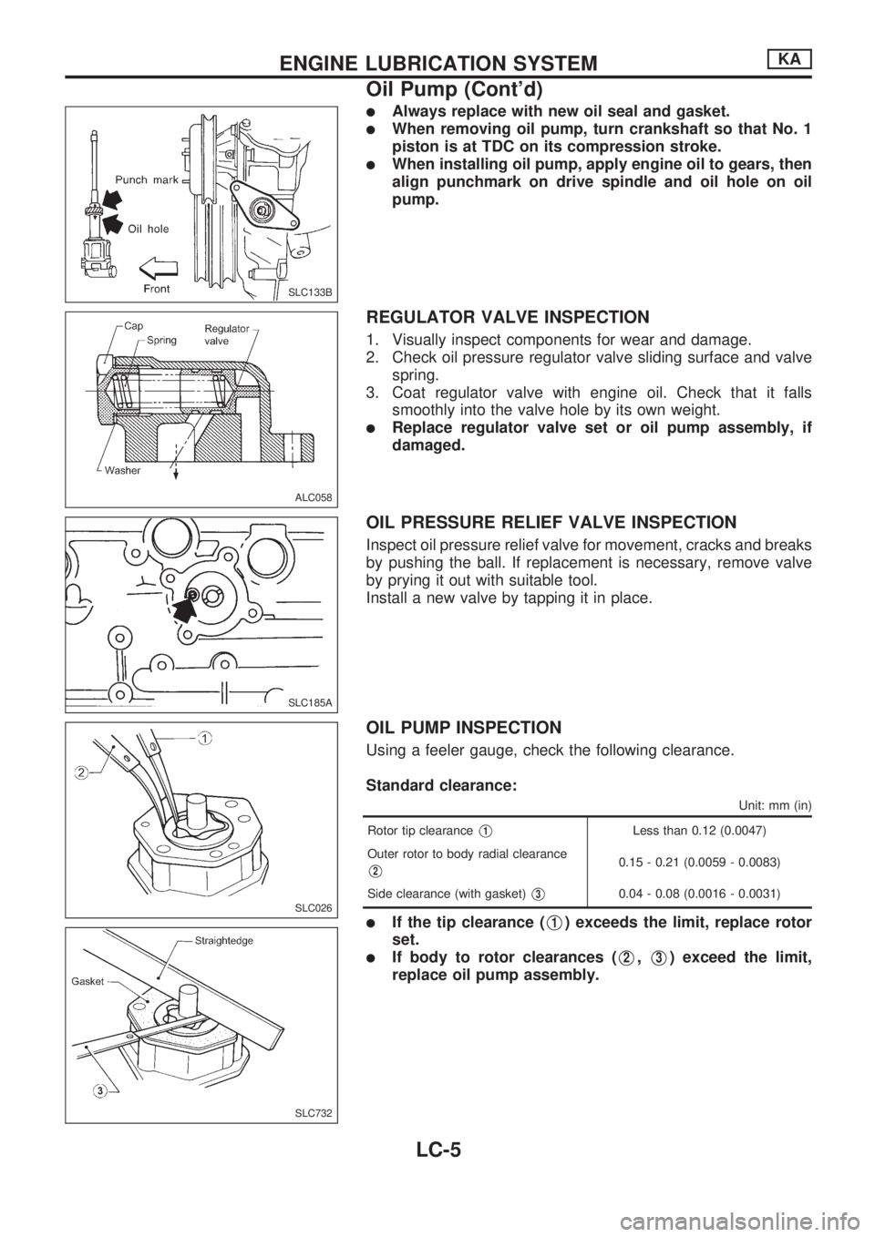
lWhen installing oil pump, apply engine oil to gears, then
align punchmark on drive spindle and oil hole on oil
pump.
REGULATOR VALVE INSPECTION
1. Visually inspect components for wear and damage.
2. Check oil pressure regulator valve sliding surface and valve
spring.
3. Coat regulator valve with engine oil. Check that it falls
smoothly into the valve hole by its own weight.
lReplace regulator valve set or oil pump assembly, if
damaged.
OIL PRESSURE RELIEF VALVE INSPECTION
Inspect oil pressure relief valve for movement, cracks and breaks
by pushing the ball. If replacement is necessary, remove valve
by prying it out with suitable tool.
Install a new valve by tapping it in place.
OIL PUMP INSPECTION
Using a feeler gauge, check the following clearance.
Standard clearance:
Unit: mm (in)
Rotor tip clearanceV1Less than 0.12 (0.0047)
Outer rotor to body radial clearance
V20.15 - 0.21 (0.0059 - 0.0083)
Side clearance (with gasket)
V30.04 - 0.08 (0.0016 - 0.0031)
lIf the tip clearance (V1) exceeds the limit, replace rotor
set.
lIf body to rotor clearances (V2,V3) exceed the limit,
replace oil pump assembly.
SLC133B
ALC058
SLC185A
SLC026
SLC732
ENGINE LUBRICATION SYSTEMKA
Oil Pump (Cont'd)
LC-5
Page 945 of 1659
Cooling Circuit
System Check
WARNING:
Never remove the radiator cap when the engine is hot. Seri-
ous burns could occur from high pressure coolant escaping
from the radiator.
Wrap a thick cloth around the cap. Slowly turn it a quarter
turn to allow built-up pressure to escape. Carefully remove
the cap by turning it all the way.
CHECKING COOLING SYSTEM HOSES
Check hoses for the following:
lImproper attachment
lLeaks
lCracks
lDamage
lChafing
lDeterioration
SLC138B
ENGINE COOLING SYSTEMKA
LC-6
Page 946 of 1659
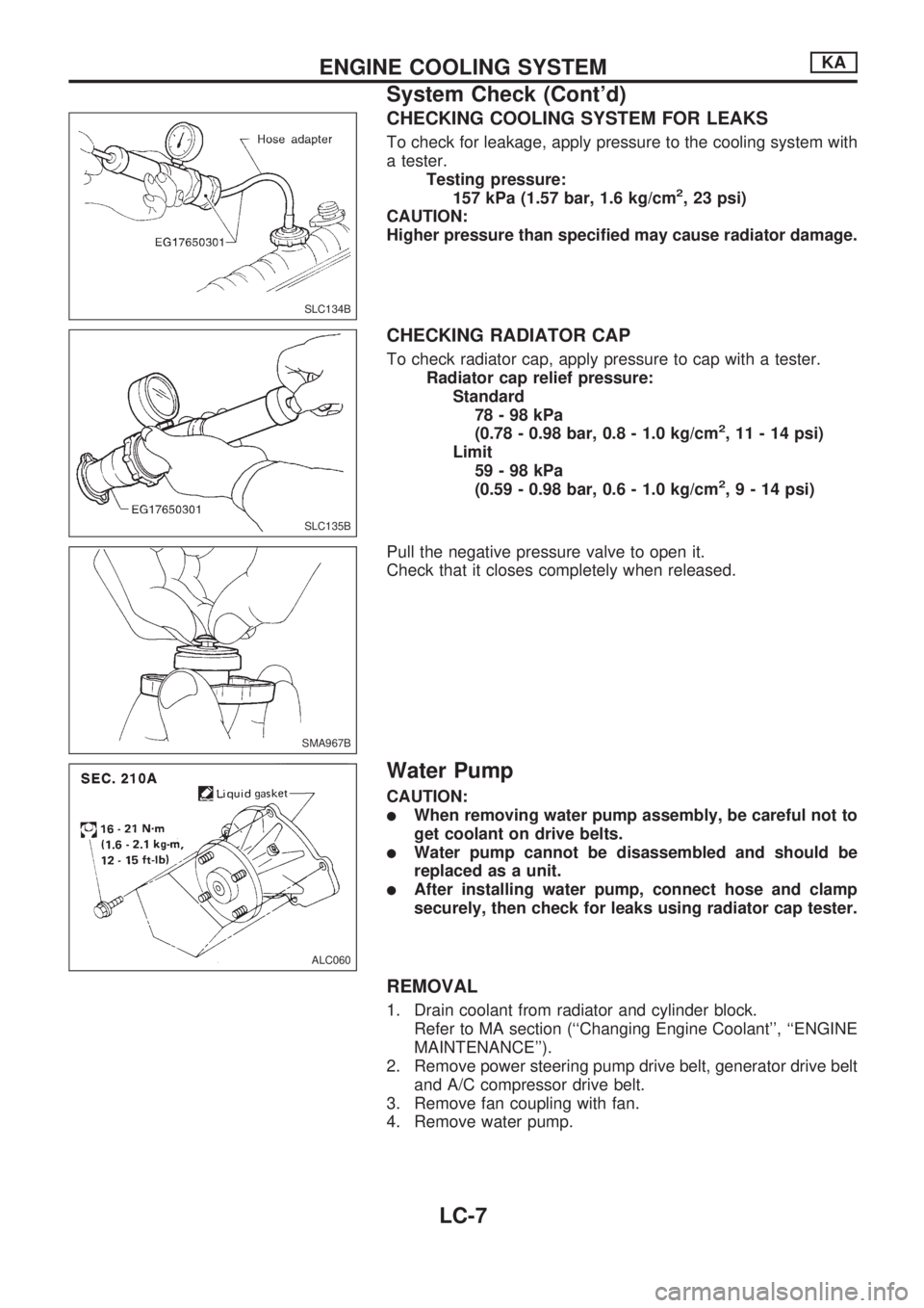
CHECKING COOLING SYSTEM FOR LEAKS
To check for leakage, apply pressure to the cooling system with
a tester.
Testing pressure:
157 kPa (1.57 bar, 1.6 kg/cm
2, 23 psi)
CAUTION:
Higher pressure than specified may cause radiator damage.
CHECKING RADIATOR CAP
To check radiator cap, apply pressure to cap with a tester.
Radiator cap relief pressure:
Standard
78-98kPa
(0.78 - 0.98 bar, 0.8 - 1.0 kg/cm
2, 11 - 14 psi)
Limit
59-98kPa
(0.59 - 0.98 bar, 0.6 - 1.0 kg/cm
2,9-14psi)
Pull the negative pressure valve to open it.
Check that it closes completely when released.
Water Pump
CAUTION:
lWhen removing water pump assembly, be careful not to
get coolant on drive belts.
lWater pump cannot be disassembled and should be
replaced as a unit.
lAfter installing water pump, connect hose and clamp
securely, then check for leaks using radiator cap tester.
REMOVAL
1. Drain coolant from radiator and cylinder block.
Refer to MA section (``Changing Engine Coolant'', ``ENGINE
MAINTENANCE'').
2. Remove power steering pump drive belt, generator drive belt
and A/C compressor drive belt.
3. Remove fan coupling with fan.
4. Remove water pump.
SLC134B
SLC135B
SMA967B
ALC060
ENGINE COOLING SYSTEMKA
System Check (Cont'd)
LC-7