1998 NISSAN PICK-UP lock
[x] Cancel search: lockPage 3 of 1659
BRAKE SYSTEM
SECTIONBR
CONTENTS
PRECAUTIONS AND PREPARATION..................... 1
Supplemental Restraint System (SRS) ``AIR
BAG'' (4WD models).............................................. 1
Supplemental Restraint System (SRS) ``AIR
BAG'' (2WD models).............................................. 1
Precautions for Brake System ............................... 1
Special Service Tools ............................................ 2
Commercial Service Tools ..................................... 2
CHECK AND ADJUSTMENT.................................... 3
Checking Brake Fluid Level ................................... 3
Checking Brake Line.............................................. 3
Changing Brake Fluid ............................................ 3
Bleeding Brake System ......................................... 4
BRAKE HYDRAULIC LINE....................................... 5
CONTROL VALVE..................................................... 7
Load Sensing Valve ............................................... 7
BRAKE PEDAL AND BRACKET............................ 10
Removal and Installation ..................................... 10
Inspection ............................................................. 11
Adjustment ........................................................... 11
MASTER CYLINDER............................................... 12
Removal ............................................................... 12
Disassembly ......................................................... 13
Inspection ............................................................. 13
Assembly.............................................................. 13
Installation ............................................................ 14
BRAKE BOOSTER.................................................. 15
On-vehicle Service ............................................... 15
Removal ............................................................... 15
Inspection ............................................................. 15
Installation ............................................................ 16
VACUUM HOSE...................................................... 17
Removal and Installation ..................................... 17Inspection ............................................................. 17
VACUUM PUMP...................................................... 19
Removal and Installation ..................................... 19
Inspection ............................................................. 19
FRONT DISC BRAKE............................................. 21
Pad Replacement ................................................ 21
Removal ............................................................... 22
Disassembly ......................................................... 23
Inspection - Caliper .............................................. 23
Inspection - Rotor ................................................ 23
Assembly.............................................................. 24
Installation ............................................................ 24
Brake Burnishing Procedure ................................ 24
REAR DRUM BRAKE............................................. 26
Removal ............................................................... 27
Inspection - Wheel Cylinder................................. 28
Wheel Cylinder Overhaul ..................................... 28
Inspection - Drum ................................................ 28
Inspection - Lining................................................ 28
Installation ............................................................ 28
PARKING BRAKE CONTROL................................ 30
Removal and Installation ..................................... 31
Inspection ............................................................. 31
Adjustment ........................................................... 31
ANTI-LOCK BRAKE SYSTEM................................ 32
Purpose ................................................................ 32
Operation ............................................................. 32
ABS Hydraulic Circuit .......................................... 32
System Components............................................ 33
System Description .............................................. 33
Removal and Installation ..................................... 35
TROUBLE DIAGNOSES......................................... 38
BR
Page 10 of 1659
REMOVAL
CAUTION:
lBe careful not to splash brake fluid on painted areas; it
may cause paint damage. If brake fluid is splashed on
painted areas, wash it away with water immediately.
lAll hoses must be free from excessive bending, twisting
and pulling.
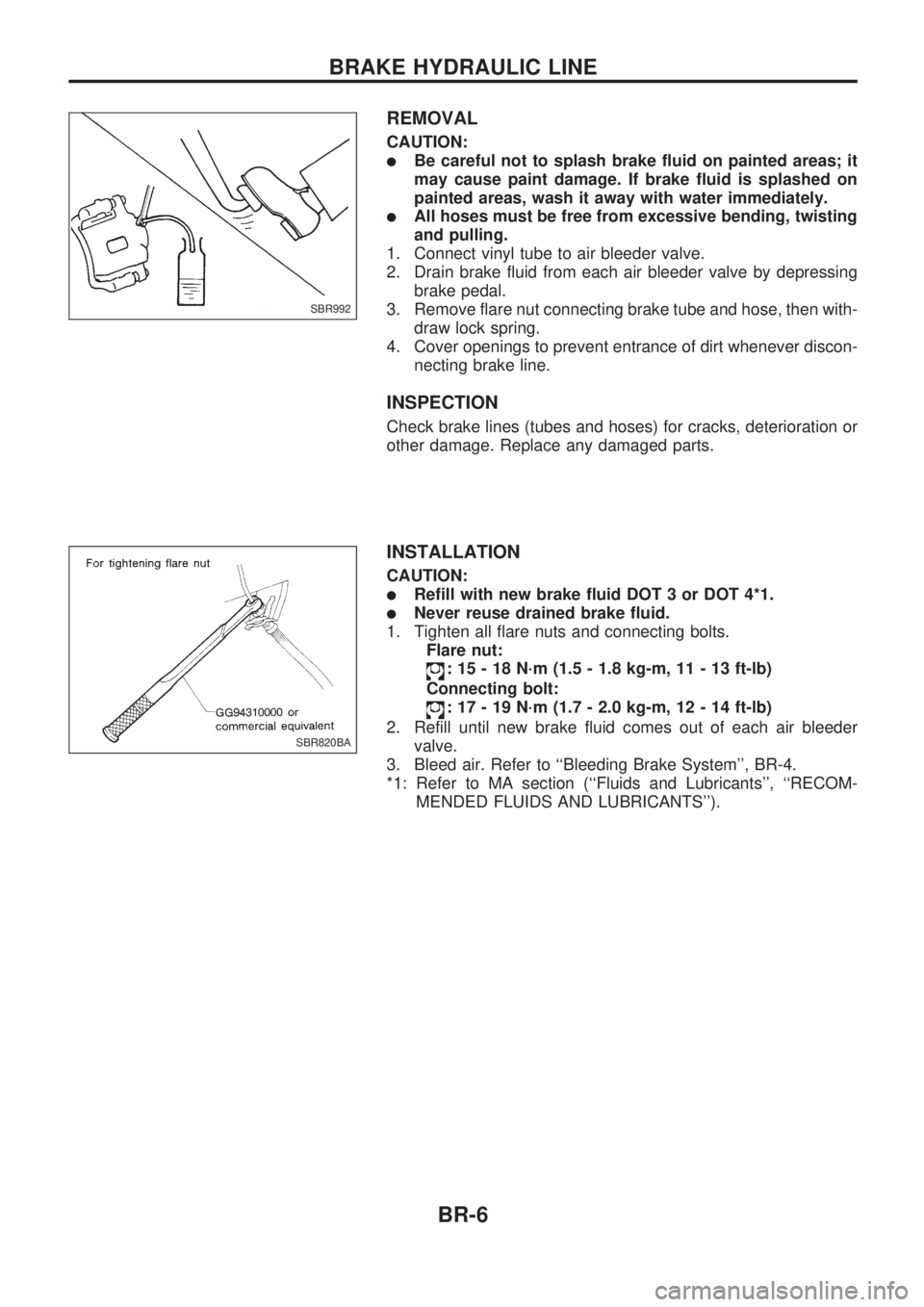
1. Connect vinyl tube to air bleeder valve.
2. Drain brake fluid from each air bleeder valve by depressing
brake pedal.
3. Remove flare nut connecting brake tube and hose, then with-
draw lock spring.
4. Cover openings to prevent entrance of dirt whenever discon-
necting brake line.
INSPECTION
Check brake lines (tubes and hoses) for cracks, deterioration or
other damage. Replace any damaged parts.
INSTALLATION
CAUTION:
lRefill with new brake fluid DOT 3 or DOT 4*1.
lNever reuse drained brake fluid.
1. Tighten all flare nuts and connecting bolts.
Flare nut:
: 15 - 18 N´m (1.5 - 1.8 kg-m, 11 - 13 ft-lb)
Connecting bolt:
: 17 - 19 N´m (1.7 - 2.0 kg-m, 12 - 14 ft-lb)
2. Refill until new brake fluid comes out of each air bleeder
valve.
3. Bleed air. Refer to ``Bleeding Brake System'', BR-4.
*1: Refer to MA section (``Fluids and Lubricants'', ``RECOM-
MENDED FLUIDS AND LUBRICANTS'').
SBR992
SBR820BA
BRAKE HYDRAULIC LINE
BR-6
Page 13 of 1659

INSPECTION
1. Ensure vehicle is unladen condition*.
* Fuel, radiator coolant and engine oil full. Spare tire, jack,
hand tools and mats in designated positions.
2. Have a driver sit in the driver's seat and one person sit on
the rear of the vehicle. Then have the person on the rear of
the vehicle slowly get off. This is necessary to stabilize sus-
pension deflection.
3. Adjust length ``L'' as follows:
a. Loosen stopper bolt locknut (2WD JIDOSHA KIKI make).
b. Pull lever against stopper bolt and adjust by turning stopper
bolt.
c. Tighten stopper bolt locknut (2WD JIDOSHA KIKI make).
Length ``L'':
2WD models
Approx. 187.3 mm (7.37 in)
4WD models
Approx. 158.1 mm (6.22 in)
4. Install pressure gauge to front and rear brake air bleeder.
5. Bleed air from the Tool.
6. Raise front brake pressure to 4,904 kPa (49.0 bar, 50
kg/cm
2, 711 psi) and 9,807 kPa (98.1 bar, 100 kg/cm2, 1,422
psi) and check rear brake pressure.
Rear brake pressure:
Refer to table below.
7. Set down weight slowly over axle center so that sensor
spring length becomes the same as when in loaded condi-
tion (refer to table below). Check rear brake pressure in the
same way described in step 6.
Unit: kPa (bar, kg/cm2, psi)
Front brake
pressureRear brake pressure
2WD 4WD
Unladen
condition
L = 187.3 mm
(7.37 in)Loaded
condition
L = 204.0 mm
(8.03 in)Unladen
condition
L = 158.1 mm
(6.22 in)Loaded
condition
L = 184.0 mm
(7.24 in)
4,904
(49.0, 50, 711)1,667 - 2,648
(16.7 - 26.5, 17
- 27, 242 - 384)3,334 - 4,315
(33.3 - 43.2, 34
- 44, 483 - 626)1,863 - 2,844
(18.6 - 28.4, 19
- 29, 270 - 412)3,334 - 4,315
(33.3 - 43.2, 34
- 44, 483 - 626)
9,807
(98.1, 100,
1,422)2,844 - 3,825
(28.4 - 38.2, 29
- 39, 412 - 555)3,629 - 5,590
(36.3 - 55.9, 37
- 57, 526 - 811)2,059 - 4,021
(20.6 - 40.2, 21
- 41, 299 - 583)3,629 - 5,590
(36.3 - 55.9, 37
- 57, 526 - 811)
SBR967D
SBR968D
SBR013B
SBR014B
CONTROL VALVE
Load Sensing Valve (Cont'd)
BR-9
Page 15 of 1659
Inspection
Check brake pedal for following items:
lBrake pedal bend
lClevis pin deformation
lCrack of any welded portion
lCrack or deformation of clevis pin stopper
Adjustment
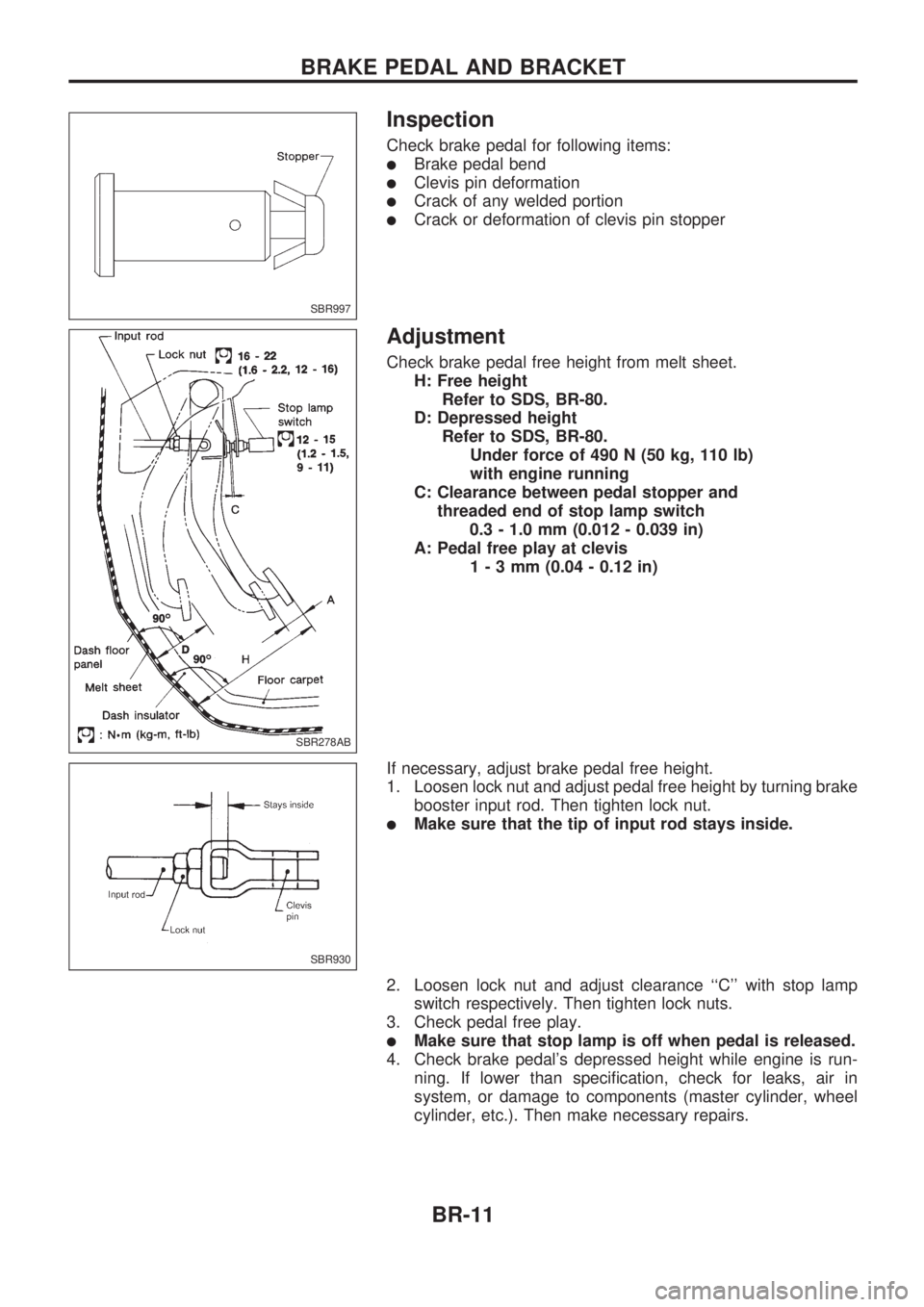
Check brake pedal free height from melt sheet.
H: Free height
Refer to SDS, BR-80.
D: Depressed height
Refer to SDS, BR-80.
Under force of 490 N (50 kg, 110 lb)
with engine running
C: Clearance between pedal stopper and
threaded end of stop lamp switch
0.3 - 1.0 mm (0.012 - 0.039 in)
A: Pedal free play at clevis
1-3mm(0.04 - 0.12 in)
If necessary, adjust brake pedal free height.
1. Loosen lock nut and adjust pedal free height by turning brake
booster input rod. Then tighten lock nut.
lMake sure that the tip of input rod stays inside.
2. Loosen lock nut and adjust clearance ``C'' with stop lamp
switch respectively. Then tighten lock nuts.
3. Check pedal free play.
lMake sure that stop lamp is off when pedal is released.
4. Check brake pedal's depressed height while engine is run-
ning. If lower than specification, check for leaks, air in
system, or damage to components (master cylinder, wheel
cylinder, etc.). Then make necessary repairs.
SBR997
SBR278AB
SBR930
BRAKE PEDAL AND BRACKET
BR-11
Page 20 of 1659
Installation
CAUTION:
lBe careful not to deform or bend brake pipes during
installation of booster.
lReplace clevis pin if damaged.
lRefill with new brake fluid DOT 3 or DOT 4*1.
lNever reuse drained brake fluid.
lTake care not to damage brake booster mounting bolt
thread when installing. Due to the narrow angle of
installation, the threads can be damaged by the dash
panel.
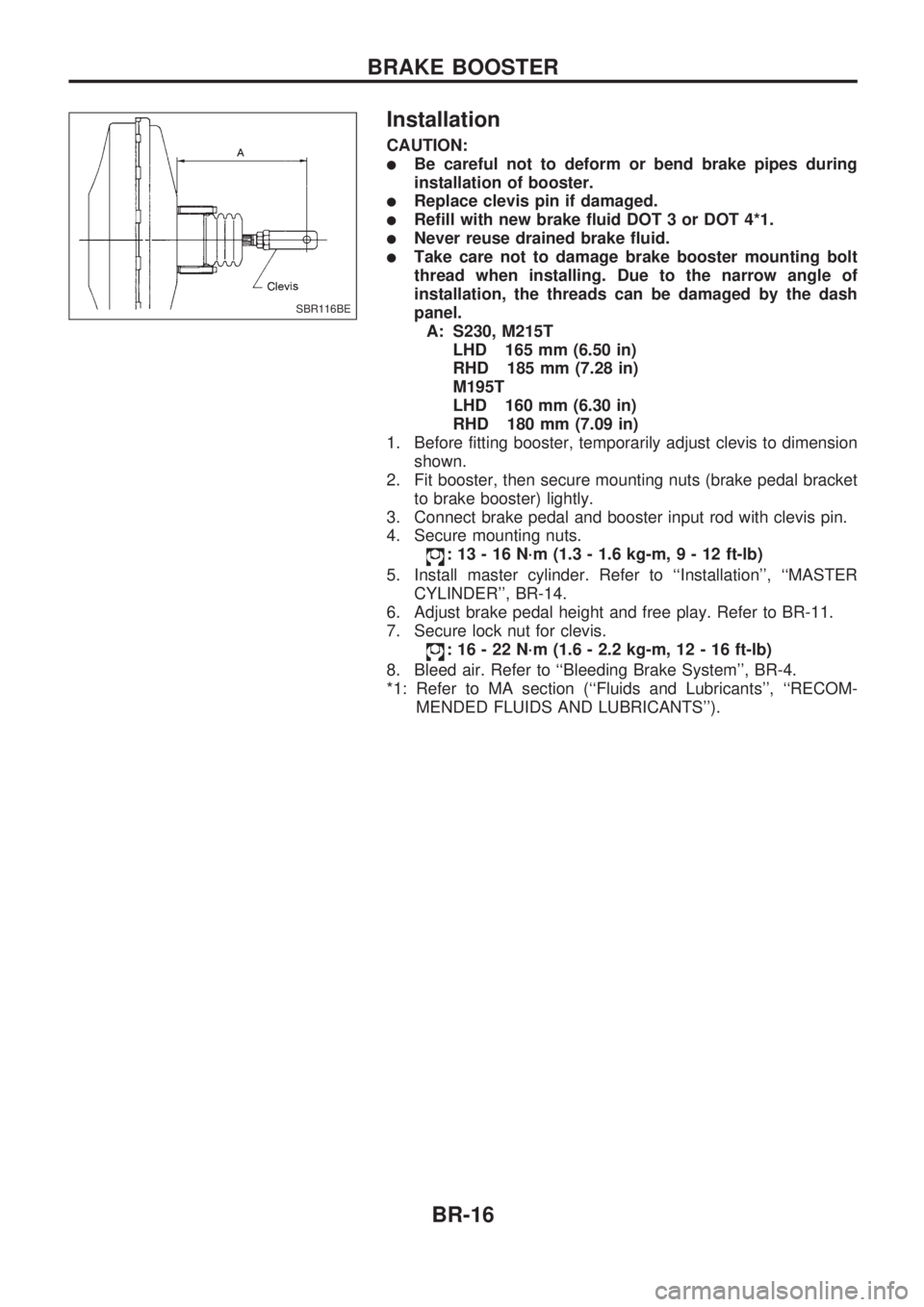
A: S230, M215T
LHD 165 mm (6.50 in)
RHD 185 mm (7.28 in)
M195T
LHD 160 mm (6.30 in)
RHD 180 mm (7.09 in)
1. Before fitting booster, temporarily adjust clevis to dimension
shown.
2. Fit booster, then secure mounting nuts (brake pedal bracket
to brake booster) lightly.
3. Connect brake pedal and booster input rod with clevis pin.
4. Secure mounting nuts.
: 13 - 16 N´m (1.3 - 1.6 kg-m,9-12ft-lb)
5. Install master cylinder. Refer to ``Installation'', ``MASTER
CYLINDER'', BR-14.
6. Adjust brake pedal height and free play. Refer to BR-11.
7. Secure lock nut for clevis.
: 16 - 22 N´m (1.6 - 2.2 kg-m, 12 - 16 ft-lb)
8. Bleed air. Refer to ``Bleeding Brake System'', BR-4.
*1: Refer to MA section (``Fluids and Lubricants'', ``RECOM-
MENDED FLUIDS AND LUBRICANTS'').
SBR116BE
BRAKE BOOSTER
BR-16
Page 27 of 1659
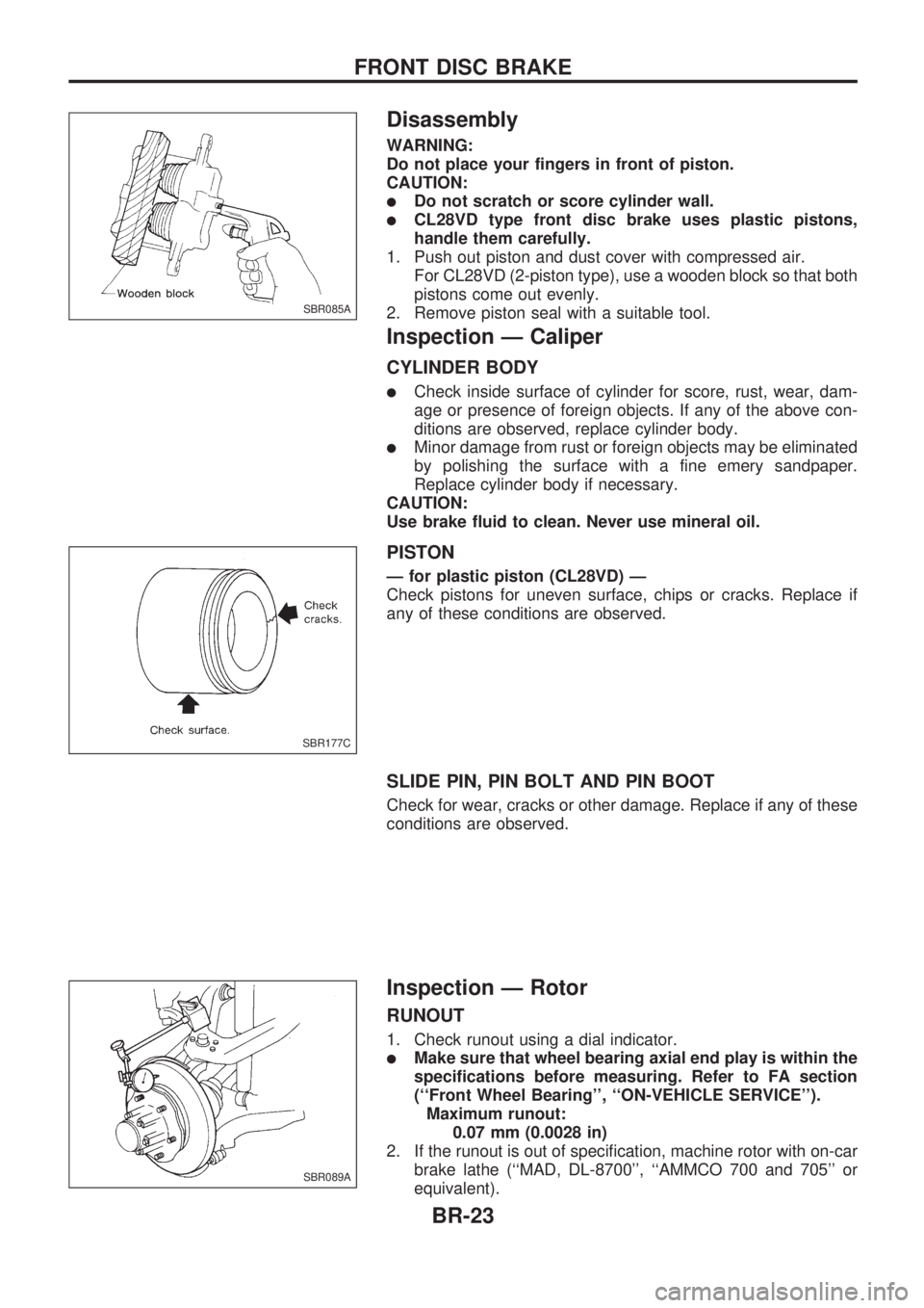
Disassembly
WARNING:
Do not place your fingers in front of piston.
CAUTION:
lDo not scratch or score cylinder wall.
lCL28VD type front disc brake uses plastic pistons,
handle them carefully.
1. Push out piston and dust cover with compressed air.
For CL28VD (2-piston type), use a wooden block so that both
pistons come out evenly.
2. Remove piston seal with a suitable tool.
Inspection Ð Caliper
CYLINDER BODY
lCheck inside surface of cylinder for score, rust, wear, dam-
age or presence of foreign objects. If any of the above con-
ditions are observed, replace cylinder body.
lMinor damage from rust or foreign objects may be eliminated
by polishing the surface with a fine emery sandpaper.
Replace cylinder body if necessary.
CAUTION:
Use brake fluid to clean. Never use mineral oil.
PISTON
Ð for plastic piston (CL28VD) Ð
Check pistons for uneven surface, chips or cracks. Replace if
any of these conditions are observed.
SLIDE PIN, PIN BOLT AND PIN BOOT
Check for wear, cracks or other damage. Replace if any of these
conditions are observed.
Inspection Ð Rotor
RUNOUT
1. Check runout using a dial indicator.
lMake sure that wheel bearing axial end play is within the
specifications before measuring. Refer to FA section
(``Front Wheel Bearing'', ``ON-VEHICLE SERVICE'').
Maximum runout:
0.07 mm (0.0028 in)
2. If the runout is out of specification, machine rotor with on-car
brake lathe (``MAD, DL-8700'', ``AMMCO 700 and 705'' or
equivalent).
SBR085A
SBR177C
SBR089A
FRONT DISC BRAKE
BR-23
Page 33 of 1659
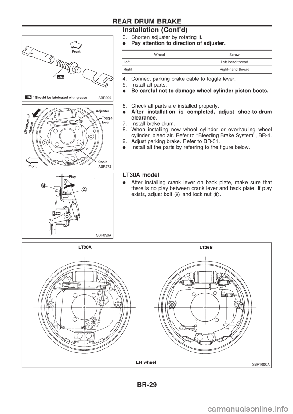
3. Shorten adjuster by rotating it.
lPay attention to direction of adjuster.
Wheel Screw
Left Left-hand thread
Right Right-hand thread
4. Connect parking brake cable to toggle lever.
5. Install all parts.
lBe careful not to damage wheel cylinder piston boots.
6. Check all parts are installed properly.
lAfter installation is completed, adjust shoe-to-drum
clearance.
7. Install brake drum.
8. When installing new wheel cylinder or overhauling wheel
cylinder, bleed air. Refer to ``Bleeding Brake System'', BR-4.
9. Adjust parking brake. Refer to BR-31.
lInstall all the parts by referring to the figure below.
LT30A model
lAfter installing crank lever on back plate, make sure that
there is no play between crank lever and back plate. If play
exists, adjust bolt
VAand lock nutVB.
ABR396
ABR372
SBR099A
SBR100CA
REAR DRUM BRAKE
Installation (Cont'd)
BR-29
Page 36 of 1659
Purpose
The Anti-Lock Brake System (ABS) consists of electronic and hydraulic components. It allows for control of
braking force so locking of the wheels can be avoided.
The ABS:
1) Improves proper tracking performance through steering wheel operation.
2) Eases obstacle avoidance through steering wheel operation.
3) Improves vehicle stability.
Operation
lWhen the vehicle speed is less than 10 km/h (6 MPH) this system does not work.
lThe Anti-Lock Brake System (ABS) has a self-test function. The system turns on the ABS warning lamp
for 1 second each time the ignition switch is turned ``ON''. After the engine is started, the ABS warning
lamp turns off. The system performs a test the first time the vehicle reaches 6 km/h (4 MPH). A
mechanical noise may be heard as the ABS performs this self-test. This is a normal part of the self-test
feature. If a malfunction is found during this check, the ABS warning lamp will stay on.
lWhile driving, a mechanical noise may be heard during ABS operation. This is a normal condition.
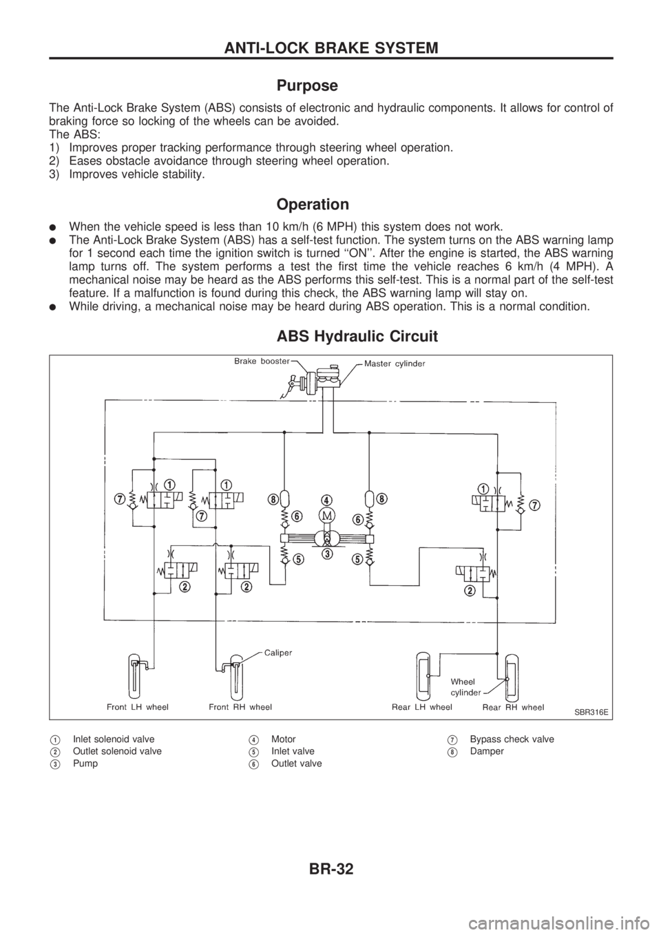
ABS Hydraulic Circuit
V1Inlet solenoid valve
V2Outlet solenoid valve
V3Pump
V4Motor
V5Inlet valve
V6Outlet valve
V7Bypass check valve
V8Damper
SBR316E
ANTI-LOCK BRAKE SYSTEM
BR-32