Page 1779 of 1807
- SERVICE SPECIFICATIONSBODY ELECTRICAL
SS-67
224 Author�: Date�:
1997 SUPRA (RM502U) (Seat Belt Warning)
1 - Ground (Constant)Battery positive voltage
9 - Ground (Ignition SW LOCK or ACC)No voltage
9 - Ground (Ignition SW ON)Battery positive voltage
ANTENNA MOTOR CONTROL RELAY
(Wire Harness Side)
1 - Ground (Constant)Battery positive voltage
4 - Ground (Ignition switch position ON)Battery positive voltage
5 - Ground (Ignition position ACC or ON)Battery positive voltage
7 - Ground (Ignition SW position ACC or ON and radio SW ON)Battery positive voltage
8 - Ground (Ignition SW position ACC or ON)Battery positive voltage
Page 1780 of 1807

SS0D7-01
SS-68
- SERVICE SPECIFICATIONSBODY
225 Author�: Date�:
1997 SUPRA (RM502U)
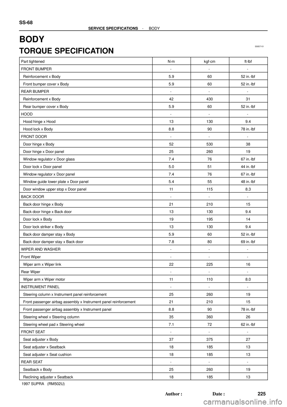
BODY
TORQUE SPECIFICATION
Part tightenedN´mkgf´cmft´lbf
FRONT BUMPER---
Reinforcement x Body5.96052 in.´lbf
Front bumper cover x Body5.96052 in.´lbf
REAR BUMPER---
Reinforcement x Body4243031
Rear bumper cover x Body5.96052 in.´lbf
HOOD---
Hood hinge x Hood131309.4
Hood lock x Body8.89078 in.´lbf
FRONT DOOR---
Door hinge x Body5253038
Door hinge x Door panel2526019
Window regulator x Door glass7.47667 in.´lbf
Door lock x Door panel5.05144 in.´lbf
Window regulator x Door panel7.47667 in.´lbf
Window guide lower plate x Door panel5.45548 in.´lbf
Door window upper stop x Door panel1111 58.3
BACK DOOR---
Back door hinge x Body2121015
Back door hinge x Back door131309.4
Door lock x Body1919514
Door lock striker x Body131309.4
Back door damper stay x Body5.96052 in.´lbf
Back door damper stay x Back door7.88069 in.´lbf
WIPER AND WASHER---
Front Wiper---
Wiper arm x Wiper link2222516
Rear Wiper---
Wiper arm x Wiper motor1111 08.0
INSTRUMENT PANEL---
Steering column x Instrument panel reinforcement2526019
Front passenger airbag assembly x Instrument panel reinforcement2121015
Front passenger airbag assembly x Instrument panel8.89078 in.´lbf
Steering wheel x Steering column3536026
Steering wheel pad x Steering wheel7.17262 in.´lbf
FRONT SEAT---
Seat adjuster x Body3737527
Seat adjuster x Seatback1818513
Seat adjuster x Seat cushion1818513
REAR SEAT---
Seatback x Body2526019
Reclining adjuster x Seatback1818513
Page 1794 of 1807

P12025
P11349
Rear
SideFront
Side
P11444
Engine
Wire
Protector(2)
(1)
P11403
Engine Wire
(2)(1) Clamp
Clamp
P11402
(2)(1)
Clamp
Clamp
Clamp
- TURBOCHARGING (2JZ-GTE)TURBOCHARGER
TC-1 1
1211 Author�: Date�:
1997 SUPRA (RM502U)
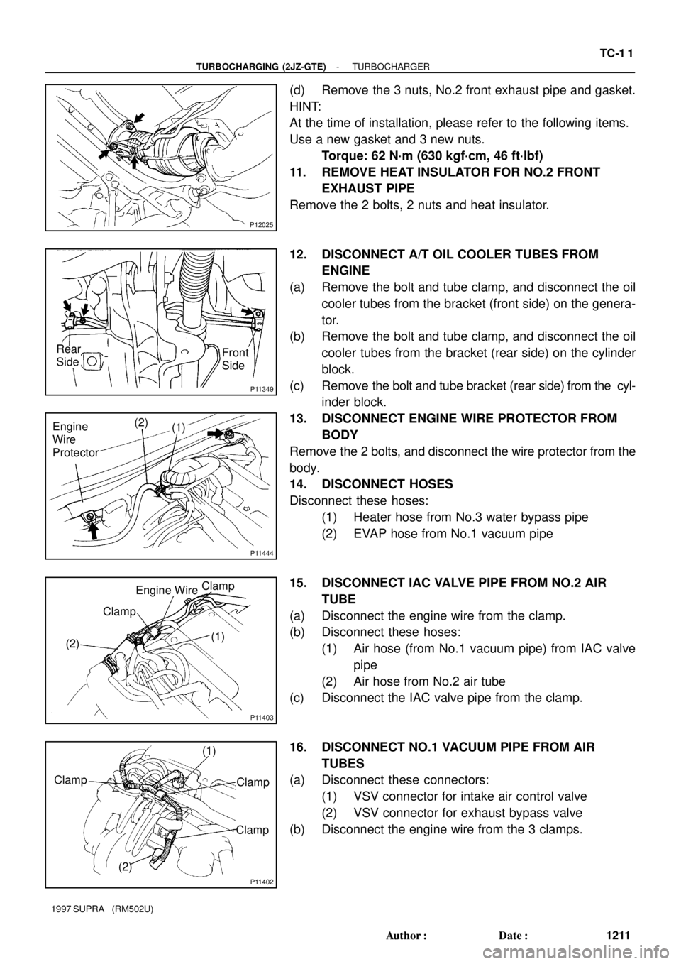
(d) Remove the 3 nuts, No.2 front exhaust pipe and gasket.
HINT:
At the time of installation, please refer to the following items.
Use a new gasket and 3 new nuts.
Torque: 62 N´m (630 kgf´cm, 46 ft´lbf)
11. REMOVE HEAT INSULATOR FOR NO.2 FRONT
EXHAUST PIPE
Remove the 2 bolts, 2 nuts and heat insulator.
12. DISCONNECT A/T OIL COOLER TUBES FROM
ENGINE
(a) Remove the bolt and tube clamp, and disconnect the oil
cooler tubes from the bracket (front side) on the genera-
tor.
(b) Remove the bolt and tube clamp, and disconnect the oil
cooler tubes from the bracket (rear side) on the cylinder
block.
(c) Remove the bolt and tube bracket (rear side) from the cyl-
inder block.
13. DISCONNECT ENGINE WIRE PROTECTOR FROM
BODY
Remove the 2 bolts, and disconnect the wire protector from the
body.
14. DISCONNECT HOSES
Disconnect these hoses:
(1) Heater hose from No.3 water bypass pipe
(2) EVAP hose from No.1 vacuum pipe
15. DISCONNECT IAC VALVE PIPE FROM NO.2 AIR
TUBE
(a) Disconnect the engine wire from the clamp.
(b) Disconnect these hoses:
(1) Air hose (from No.1 vacuum pipe) from IAC valve
pipe
(2) Air hose from No.2 air tube
(c) Disconnect the IAC valve pipe from the clamp.
16. DISCONNECT NO.1 VACUUM PIPE FROM AIR
TUBES
(a) Disconnect these connectors:
(1) VSV connector for intake air control valve
(2) VSV connector for exhaust bypass valve
(b) Disconnect the engine wire from the 3 clamps.
Page 1798 of 1807

P11426
Oil Hole
No.1
No.2Oil Hole
Oil Hole
Oil Hole
P11424
(1)
(2)
- TURBOCHARGING (2JZ-GTE)TURBOCHARGER
TC-15
1215 Author�: Date�:
1997 SUPRA (RM502U)
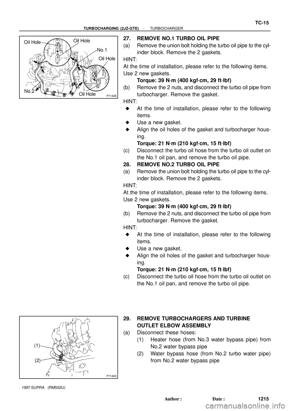
27. REMOVE NO.1 TURBO OIL PIPE
(a) Remove the union bolt holding the turbo oil pipe to the cyl-
inder block. Remove the 2 gaskets.
HINT:
At the time of installation, please refer to the following items.
Use 2 new gaskets.
Torque: 39 N´m (400 kgf´cm, 29 ft´lbf)
(b) Remove the 2 nuts, and disconnect the turbo oil pipe from
turbocharger. Remove the gasket.
HINT:
�At the time of installation, please refer to the following
items.
�Use a new gasket.
�Align the oil holes of the gasket and turbocharger hous-
ing.
Torque: 21 N´m (210 kgf´cm, 15 ft´lbf)
(c) Disconnect the turbo oil hose from the turbo oil outlet on
the No.1 oil pan, and remove the turbo oil pipe.
28. REMOVE NO.2 TURBO OIL PIPE
(a) Remove the union bolt holding the turbo oil pipe to the cyl-
inder block. Remove the 2 gaskets.
HINT:
At the time of installation, please refer to the following items.
Use 2 new gaskets.
Torque: 39 N´m (400 kgf´cm, 29 ft´lbf)
(b) Remove the 2 nuts, and disconnect the turbo oil pipe from
turbocharger. Remove the gasket.
HINT:
�At the time of installation, please refer to the following
items.
�Use a new gasket.
�Align the oil holes of the gasket and turbocharger hous-
ing.
Torque: 21 N´m (210 kgf´cm, 15 ft´lbf)
(c) Disconnect the turbo oil hose from the turbo oil outlet on
the No.1 oil pan, and remove the turbo oil pipe.
29. REMOVE TURBOCHARGERS AND TURBINE
OUTLET ELBOW ASSEMBLY
(a) Disconnect these hoses:
(1) Heater hose (from No.3 water bypass pipe) from
No.2 water bypass pipe
(2) Water bypass hose (from No.2 turbo water pipe)
from No.2 water bypass pipe