Page 1660 of 1807
SA0PK-02
W00616
Washer
Drive Shaft
Parking Brake CableBrake Caliper
Hub Bolt ABS Speed
SensorUpper Suspension Arm
Shoe Guide Plate
Lower Suspension
Arm No. 1Rear Shock
Absorber
Parking Brake
Exhaust Pipe Supprot
O-Ring Lower Suspension
Arm No. 2
Lower Suspension
Arm BraceStrut Rod
Exhaust PipeCotter Pin
Exhaust Pipe Supprot
RingDisc
Lock Cap
� Non-reusable part
- SUSPENSION AND AXLEREAR AXLE HUB
SA-41
1731 Author�: Date�:
1997 SUPRA (RM502U)
REAR AXLE HUB
COMPONENTS
Page 1662 of 1807

SA0PL-02
Z18437
R 1111 0
- SUSPENSION AND AXLEREAR AXLE HUB
SA-43
1733 Author�: Date�:
1997 SUPRA (RM502U)
REMOVAL
1. REMOVE REAR WHEEL
Torque: 103 N´m (1,050 kgf´cm, 76 ft´lbf)
2. REMOVE BRAKE CALIPER AND DISC
(a) Remove the 2 bolts and brake caliper from the rear axle
hub.
Torque: 104 N´m (1,065 kgf´cm, 77 ft´lbf)
(b) Support the brake caliper securely.
(c) Place matchmarks on the disc and axle hub.
(d) Remove the disc.
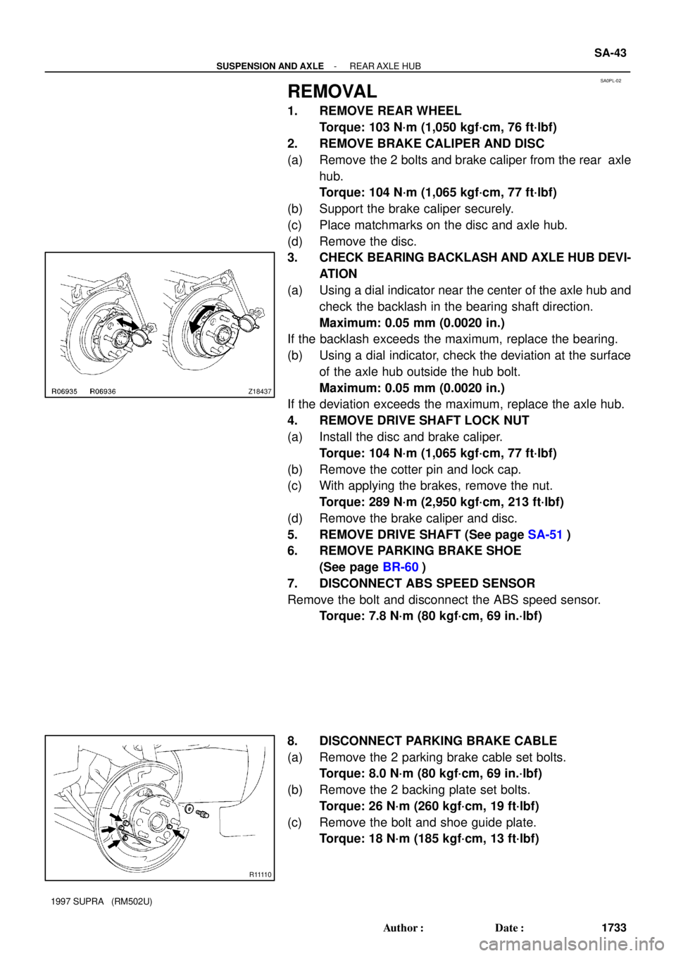
3. CHECK BEARING BACKLASH AND AXLE HUB DEVI-
ATION
(a) Using a dial indicator near the center of the axle hub and
check the backlash in the bearing shaft direction.
Maximum: 0.05 mm (0.0020 in.)
If the backlash exceeds the maximum, replace the bearing.
(b) Using a dial indicator, check the deviation at the surface
of the axle hub outside the hub bolt.
Maximum: 0.05 mm (0.0020 in.)
If the deviation exceeds the maximum, replace the axle hub.
4. REMOVE DRIVE SHAFT LOCK NUT
(a) Install the disc and brake caliper.
Torque: 104 N´m (1,065 kgf´cm, 77 ft´lbf)
(b) Remove the cotter pin and lock cap.
(c) With applying the brakes, remove the nut.
Torque: 289 N´m (2,950 kgf´cm, 213 ft´lbf)
(d) Remove the brake caliper and disc.
5. REMOVE DRIVE SHAFT (See page SA-51)
6. REMOVE PARKING BRAKE SHOE
(See page BR-60)
7. DISCONNECT ABS SPEED SENSOR
Remove the bolt and disconnect the ABS speed sensor.
Torque: 7.8 N´m (80 kgf´cm, 69 in.´lbf)
8. DISCONNECT PARKING BRAKE CABLE
(a) Remove the 2 parking brake cable set bolts.
Torque: 8.0 N´m (80 kgf´cm, 69 in.´lbf)
(b) Remove the 2 backing plate set bolts.
Torque: 26 N´m (260 kgf´cm, 19 ft´lbf)
(c) Remove the bolt and shoe guide plate.
Torque: 18 N´m (185 kgf´cm, 13 ft´lbf)
Page 1668 of 1807
SA0PQ-02
W02907
Washer
Drive Shaft
Lower Suspension
Arm BraceLock Cap
Cotter Pin
Boot Clamp
Exhaust Pipe
Supprot Ring
Outboard Joint
with Drive Shaft Washer Washer
Washer
Boot Clamp Exhaust Pipe2JZ-GTE:
2JZ-GTE:
Boot Clamp Boot Clamp
Boot
Snap Ring
Inboard Joint
End Cover
Gasket
2JZ-GTE:
End CoverInboard Joint
Inboard Joint Cover
Boot Clamp
Boot Clamp
Boot
Non-reusable part SA-50
- SUSPENSION AND AXLEREAR DRIVE SHAFT
1740 Author�: Date�:
1997 SUPRA (RM502U)
REAR DRIVE SHAFT
COMPONENTS
Page 1669 of 1807

SA0PR-02
Z08967
TailpipeCenter Pipe
R07037
Matchmarks
R07024
R06937
- SUSPENSION AND AXLEREAR DRIVE SHAFT
SA-51
1741 Author�: Date�:
1997 SUPRA (RM502U)
REMOVAL
1. REMOVE REAR WHEEL
Torque: 103 N´m (1,050 kgf´cm, 76 ft´lbf)
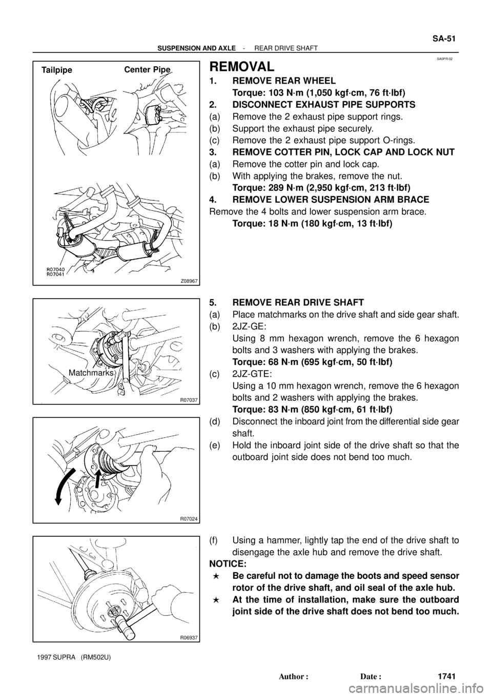
2. DISCONNECT EXHAUST PIPE SUPPORTS
(a) Remove the 2 exhaust pipe support rings.
(b) Support the exhaust pipe securely.
(c) Remove the 2 exhaust pipe support O-rings.
3. REMOVE COTTER PIN, LOCK CAP AND LOCK NUT
(a) Remove the cotter pin and lock cap.
(b) With applying the brakes, remove the nut.
Torque: 289 N´m (2,950 kgf´cm, 213 ft´lbf)
4. REMOVE LOWER SUSPENSION ARM BRACE
Remove the 4 bolts and lower suspension arm brace.
Torque: 18 N´m (180 kgf´cm, 13 ft´lbf)
5. REMOVE REAR DRIVE SHAFT
(a) Place matchmarks on the drive shaft and side gear shaft.
(b) 2JZ-GE:
Using 8 mm hexagon wrench, remove the 6 hexagon
bolts and 3 washers with applying the brakes.
Torque: 68 N´m (695 kgf´cm, 50 ft´lbf)
(c) 2JZ-GTE:
Using a 10 mm hexagon wrench, remove the 6 hexagon
bolts and 2 washers with applying the brakes.
Torque: 83 N´m (850 kgf´cm, 61 ft´lbf)
(d) Disconnect the inboard joint from the differential side gear
shaft.
(e) Hold the inboard joint side of the drive shaft so that the
outboard joint side does not bend too much.
(f) Using a hammer, lightly tap the end of the drive shaft to
disengage the axle hub and remove the drive shaft.
NOTICE:
�Be careful not to damage the boots and speed sensor
rotor of the drive shaft, and oil seal of the axle hub.
�At the time of installation, make sure the outboard
joint side of the drive shaft does not bend too much.
Page 1674 of 1807

W00623
SST
30°
R06938
0.8 mm (0.031 in.)
or less
SST
R08199
SA1465
SA-56
- SUSPENSION AND AXLEREAR DRIVE SHAFT
1746 Author�: Date�:
1997 SUPRA (RM502U)
6. 2JZ-GTE:
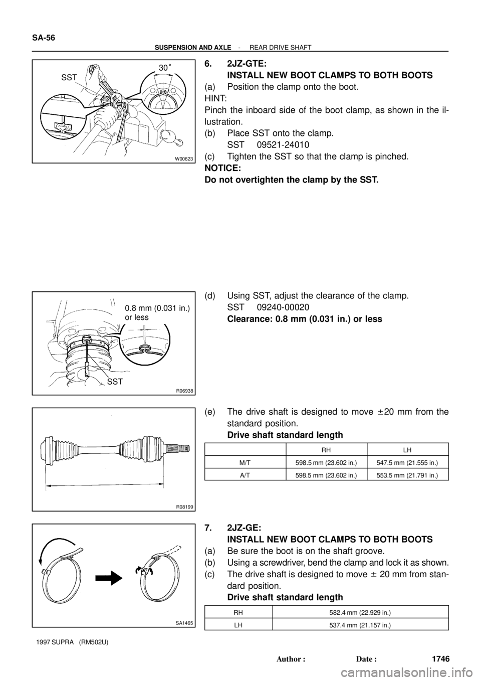
INSTALL NEW BOOT CLAMPS TO BOTH BOOTS
(a) Position the clamp onto the boot.
HINT:
Pinch the inboard side of the boot clamp, as shown in the il-
lustration.
(b) Place SST onto the clamp.
SST 09521-24010
(c) Tighten the SST so that the clamp is pinched.
NOTICE:
Do not overtighten the clamp by the SST.
(d) Using SST, adjust the clearance of the clamp.
SST 09240-00020
Clearance: 0.8 mm (0.031 in.) or less
(e) The drive shaft is designed to move ±20 mm from the
standard position.
Drive shaft standard length
RHLH
M/T598.5 mm (23.602 in.)547.5 mm (21.555 in.)
A/T598.5 mm (23.602 in.)553.5 mm (21.791 in.)
7. 2JZ-GE:
INSTALL NEW BOOT CLAMPS TO BOTH BOOTS
(a) Be sure the boot is on the shaft groove.
(b) Using a screwdriver, bend the clamp and lock it as shown.
(c) The drive shaft is designed to move ± 20 mm from stan-
dard position.
Drive shaft standard length
RH582.4 mm (22.929 in.)
LH537.4 mm (21.157 in.)
Page 1676 of 1807
SA0PV-02
W02906
Differential
Differential Side Gear Shaft Oil Seal
Rear Drive Shaft Washer
Exhaust Pipe Lower Suspension Arm Brace
O-Ring
Exhaust Pipe
Support Ring Gasket
Non-reusable partWasher
WasherSnap Ring
Cotter Pin
Lock Cap 2JZ-GTE
- SUSPENSION AND AXLEREAR DIFFERENTIAL SIDE GEAR SHAFT OIL SEAL
SA-59
1749 Author�: Date�:
1997 SUPRA (RM502U)
REAR DIFFERENTIAL SIDE GEAR SHAFT OIL SEAL
COMPONENTS
Page 1692 of 1807

SA1143
Boiling Water
SA1158
Matchmarks
SA1148
SA1180
64 N´m (650 kgf´cm, 47 ft´lbf)
60 - 90°
R15897
SST
SST
- SUSPENSION AND AXLEREAR DIFFERENTIAL CARRIER
SA-75
1765 Author�: Date�:
1997 SUPRA (RM502U)
3. INSTALL RING GEAR ON DIFFERENTIAL CASE
(a) Clean the contact surfaces of the differential case, the
threads of the ring gear and differential case.
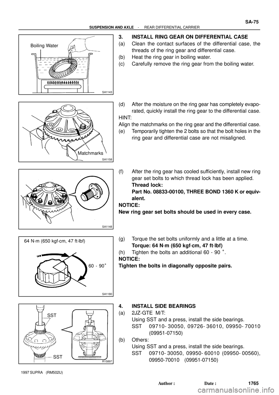
(b) Heat the ring gear in boiling water.
(c) Carefully remove the ring gear from the boiling water.
(d) After the moisture on the ring gear has completely evapo-
rated, quickly install the ring gear to the differential case.
HINT:
Align the matchmarks on the ring gear and the differential case.
(e) Temporarily tighten the 2 bolts so that the bolt holes in the
ring gear and differential case are not misaligned.
(f) After the ring gear has cooled sufficiently, install new ring
gear set bolts to which thread lock has been applied.
Thread lock:
Part No. 08833-00100, THREE BOND 1360 K or equiv-
alent.
NOTICE:
New ring gear set bolts should be used in every case.
(g) Torque the set bolts uniformly and a little at a time.
Torque: 64 N´m (650 kgf´cm, 47 ft´lbf)
(h) Tighten the bolts an additional 60 - 90 °.
NOTICE:
Tighten the bolts in diagonally opposite pairs.
4. INSTALL SIDE BEARINGS
(a) 2JZ-GTE M/T:
Using SST and a press, install the side bearings.
SST 09710- 30050, 09726- 36010, 09950- 70010
(09951-07150)
(b) Others:
Using SST and a press, install the side bearings.
SST 09710- 30050, 09950- 60010 (09950- 00560),
09950-70010 (09951-07150)
Page 1712 of 1807
SA0QB-02
W02905
Bushing
Shock Absorber
Stabilizer
Bar Link
Adjusting Cam Washer
Lower Suspension
Arm No. 2
Brake
Caliper Drive ShaftABS Speed
Sensor
Lower Suspension
Arm No. 1
Bushing
Upper Suspension
Arm
�
Cotter Pin Lock Cap
Exhaust Pipe Support O-Ring Nut
Strut Rod Lower Suspension
Arm BraceAdjusting
Cam
Parking Brake Cable
Bushing
Exhaust Pipe Support Ring
Exhaust Pipe
Non-reusable part
SA-96
- SUSPENSION AND AXLEREAR UPPER SUSPENSION ARM
1786 Author�: Date�:
1997 SUPRA (RM502U)
REAR UPPER SUSPENSION ARM
COMPONENTS