Page 1464 of 1807

Q08242
TOYOTA Hand-Held Tester
DLC3
P11445
Fuel Return
Hose
Pinch SF-4
- SFI (2JZ-GTE)SFI SYSTEM
1330 Author�: Date�:
1997 SUPRA (RM502U)
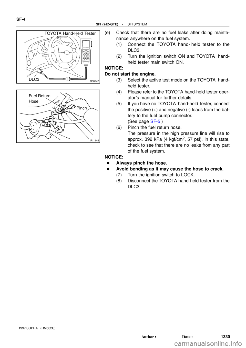
(e) Check that there are no fuel leaks after doing mainte-
nance anywhere on the fuel system.
(1) Connect the TOYOTA hand- held tester to the
DLC3.
(2) Turn the ignition switch ON and TOYOTA hand-
held tester main switch ON.
NOTICE:
Do not start the engine.
(3) Select the active test mode on the TOYOTA hand-
held tester.
(4) Please refer to the TOYOTA hand-held tester oper-
ator 's manual for further details.
(5) If you have no TOYOTA hand-held tester, connect
the positive (+) and negative (-) leads from the bat-
tery to the fuel pump connector.
(See page SF-5)
(6) Pinch the fuel return hose.
The pressure in the high pressure line will rise to
approx. 392 kPa (4 kgf/cm
2, 57 psi). In this state,
check to see that there are no leaks from any part
of the fuel system.
NOTICE:
�Always pinch the hose.
�Avoid bending as it may cause the hose to crack.
(7) Turn the ignition switch to LOCK.
(8) Disconnect the TOYOTA hand-held tester from the
DLC3.
Page 1465 of 1807

Q08242
TOYOTA Hand-Held Tester
DLC3
P11446Fuel Inlet Hose
P12558
Fuel Inlet
Hose
SF0GH-01
Z13307
Fuel Inlet HoseSST
Gasket
SSTSST
Gasket(Union)
- SFI (2JZ-GTE)FUEL PUMP
SF-5
1331 Author�: Date�:
1997 SUPRA (RM502U)
FUEL PUMP
ON-VEHICLE INSPECTION
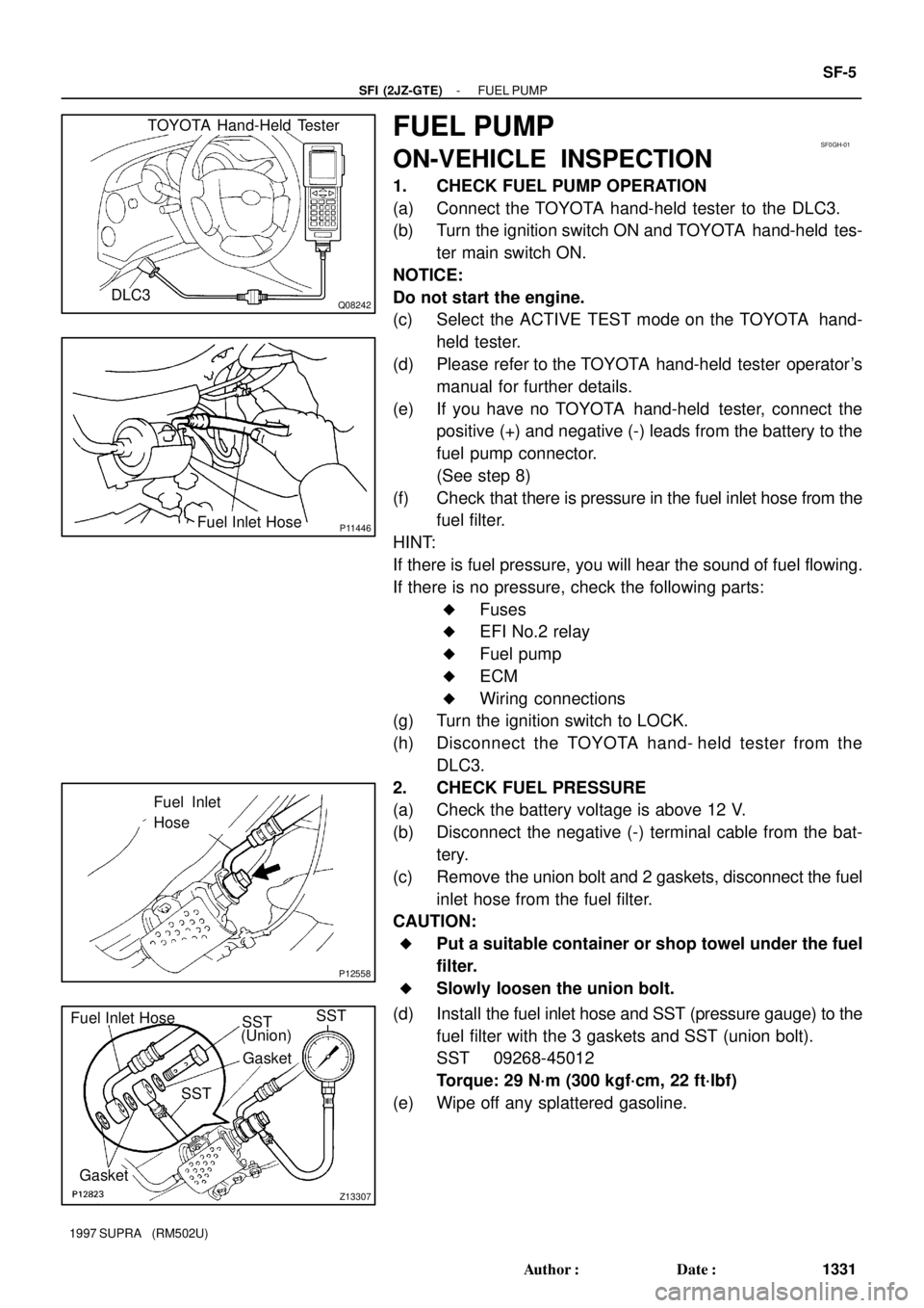
1. CHECK FUEL PUMP OPERATION
(a) Connect the TOYOTA hand-held tester to the DLC3.
(b) Turn the ignition switch ON and TOYOTA hand-held tes-
ter main switch ON.
NOTICE:
Do not start the engine.
(c) Select the ACTIVE TEST mode on the TOYOTA hand-
held tester.
(d) Please refer to the TOYOTA hand-held tester operator's
manual for further details.
(e) If you have no TOYOTA hand-held tester, connect the
positive (+) and negative (-) leads from the battery to the
fuel pump connector.
(See step 8)
(f) Check that there is pressure in the fuel inlet hose from the
fuel filter.
HINT:
If there is fuel pressure, you will hear the sound of fuel flowing.
If there is no pressure, check the following parts:
�Fuses
�EFI No.2 relay
�Fuel pump
�ECM
�Wiring connections
(g) Turn the ignition switch to LOCK.
(h) Disconnect the TOYOTA hand- held tester from the
DLC3.
2. CHECK FUEL PRESSURE
(a) Check the battery voltage is above 12 V.
(b) Disconnect the negative (-) terminal cable from the bat-
tery.
(c) Remove the union bolt and 2 gaskets, disconnect the fuel
inlet hose from the fuel filter.
CAUTION:
�Put a suitable container or shop towel under the fuel
filter.
�Slowly loosen the union bolt.
(d) Install the fuel inlet hose and SST (pressure gauge) to the
fuel filter with the 3 gaskets and SST (union bolt).
SST 09268-45012
Torque: 29 N´m (300 kgf´cm, 22 ft´lbf)
(e) Wipe off any splattered gasoline.
Page 1486 of 1807

Q08242
TOYOTA Hand-Held Tester
DLC3
P12548
SST (Wire)
Connect
P12549
- SFI (2JZ-GTE)INJECTOR
SF-27
1353 Author�: Date�:
1997 SUPRA (RM502U)
(i) Connect the TOYOTA hand-held tester to the DLC3.
(j) Turn the ignition switch ON and TOYOTA hand-held tes-
ter main switch ON.
NOTICE:
Do not start the engine.
(k) Select the active test mode on the TOYOTA hand-held
tester.
(l) Please refer to the TOYOTA hand-held tester operator's
manual for further details.
(m) If you have no TOYOTA hand-held tester, connect the
positive (+) and negative (-) leads from the battery to the
fuel pump connector.
(n) Connect SST (wire) to the injector and battery for 15 se-
conds, and measure the injection volume with a gra-
duated cylinder. Test each injector 2 or 3 times.
SST 09842-30060
Injection volume:
111 - 141 cm
3 (6.8 - 8.6 cu in.) per 15 sec.
Difference between each injector:
10 cm
3 (0.6 cu in.) or less
If the injection volume is not as specified, replace the injector.
2. INSPECT LEAKAGE
(a) In the condition above, disconnect the tester probes of
SST (wire) from the battery and check the fuel leakage
from the injector.
SST 09842-30060
Fuel drop:
One drop or less per minutes
(b) Turn the ignition switch to LOCK.
(c) Disconnect the negative (-) terminal cable from the bat-
tery.
(d) Remove the SST.
SST 09268-41046
(e) Reconnect the fuel inlet hose to the fuel filter with 2 new
gaskets and the union bolt.
Torque: 29 N´m (300 kgf´cm, 22 ft´lbf)
(f) Reconnect the fuel return hose to the fuel return pipe.
(g) Remove the 6 bolts, 3 injector holders and 6 insulators.
(h) Disconnect the TOYOTA hand- held tester from the
DLC3.
Page 1501 of 1807
Z09125
0.65 mm
S00022
Ohmmeter
IDL
E2 Turn
B02446
B02858
0.54 or 0.70 mm
Ohmmeter
E2IDL
P11455
Ohmmeter
A B
A-B-
- SFI (2JZ-GTE)THROTTLE BODY
SF-45
1371 Author�: Date�:
1997 SUPRA (RM502U)
(b) Insert a 0.65 mm (0.026 in.) feeler gauge between the
throttle stop screw and stop lever.
(c) Connect the tester probe of an ohmmeter to the terminals
IDL and E2 of the sensor.
(d) Gradually turn the sensor clockwise until the ohmmeter
deflects, and secure it with the 2 set screws.
(e) Recheck the continuity between terminals IDL and E2.
Clearance between
lever and stop screwContinuity (IDL - E2)
0.54 mm (0.021 in.)Continuity
0.75 mm (0.028 in.)No continuity
(f) Reconnect the vacuum hose to the throttle body.
5. INSPECT SUB-THROTTLE ACTUATOR
Using an ohmmeter, measure the resistance between the ter-
minals (A and A-,to B and B-).
Resistance: 0.82 - 0.98 W at 20°C (68°F)
If the resistance is not as specified, replace the actuator.
Page 1503 of 1807
Z09127
Sub-Throttle
Valve
Closed0.45 mm
S00023
Ohmmeter
E2
IDL
Turn
Z09130
Sub-Throttle
Valve
0.41 or
0.48 mm
Closed
Ohmmeter
E2
IDL
VTA
VC
- SFI (2JZ-GTE)THROTTLE BODY
SF-47
1373 Author�: Date�:
1997 SUPRA (RM502U)
(b) Set the sub-throttle valve to fully closed position.
(c) Insert a 0.45 mm (0.018 in.) feeler gauge, between the
throttle stop screw and throttle valve gear.
(d) Connect the tester probe of an ohmmeter to the terminals
IDL and E2 of the sensor.
(e) Gradually turn the sensor clockwise until the ohmmeter
deflects, and secure it with the 2 set screws.
(f) Recheck the continuity between terminals IDL and E2.
Clearance between
lever and stop screwContinuity (IDL - E2)
0.41 mm (0.016 in.)Continuity
0.48 mm (0.019 in.)No continuity
10. REINSTALL SUB-THROTTLE ACTUATOR
Install the sub-throttle actuator with the 4 screws.
Page 1543 of 1807

Z05962
P11595
P11594
P10652
Type A
Type BAB
AB
Z05963
CORRECT WRONGWRONG
- CHARGINGCHARGING SYSTEM
CH-3
1526 Author�: Date�:
1997 SUPRA (RM502U)
5. INSPECT DRIVE BELT
HINT:
A belt tensioner is used, so checking the belt tension is not nec-
essary.
(a) Visually check the drive belt for excessive wear, frayed
cords, etc.
If necessary, replace the drive belt.
HINT:
�Cracks on the rib side of a drive belt are considered ac-
ceptable. If the drive belt has chunks missing from the
ribs, it should be replaced.
�The drive belt tension can be released by turning the belt
tensioner clockwise.
(b) Check the belt tensioner operation.
�Check that the belt tensioner moves downward
when the drive belt is pressed down at the points in-
dicated in the illustration with approx. 98 N (10 kgf,
22.0 lbf) of force.
�Check the alignment of the belt tensioner pulley to
make sure the drive belt will not slip off the pulley.
If necessary, replace the belt tensioner.
�Check that the arrow mark on the belt tensioner falls
within area A of the scale.
If it is outside area A, replace the drive belt.
HINT:
�When a new belt is installed, it should lie within area B. If
not, the drive belt is not correct.
�After installing a drive belt, check that it fits properly in the
ribbed grooves.
�Check by hand to confirm that the belt has not slipped out
of the groove on the bottom of the pulley.
Page 1550 of 1807
P10835
Turn
SST (B)SST (A)
Z00040
SST (C)
Turn
P10836
Turn
SST (B)SST (A)
P10635
P18676
SST CH-10
- CHARGINGGENERATOR
1533 Author�: Date�:
1997 SUPRA (RM502U)
5. REMOVE PULLEY
(a) Hold SST (A) with a torque wrench, and tighten SST (B)
clockwise to the specified torque.
SST 09820-63010
Torque: 39 N´m (400 kgf´cm, 29 ft´lbf)
(b) Check that SST (A) is secured to the rotor shaft.
(c) Mount SST (C) in a vise.
(d) Insert SST (B) into SST (C), and attach the pulley nut to
SST (C).
(e) To loosen the pulley nut, turn SST (A) in the direction
shown in the illustration.
NOTICE:
To prevent damage to the rotor shaft, do not loosen the
pulley nut more than one-half of a turn.
(f) Remove the generator from SST (C).
(g) Turn SST (B), and remove SST (A and B).
(h) Remove the pulley nut and pulley.
6. REMOVE RECTIFIER END FRAME
(a) Remove the 3 nuts.
(b) Using SST, remove the rectifier end frame.
SST 09950-40010
(c) Remove the generator washer.
7. REMOVE ROTOR FROM DRIVE END FRAME
Page 1555 of 1807

CH03Q-01
P10637
P10640
29 mm
Socket
Wrench
P10635
P10835
Turn
SST (A)
SST (B)
Z00045
SST (C)
- CHARGINGGENERATOR
CH-15
1538 Author�: Date�:
1997 SUPRA (RM502U)
REASSEMBLY
1. PLACE DRIVE END FRAME ON PULLEY
2. INSTALL ROTOR TO DRIVE END FRAME
3. INSTALL RECTIFIER END FRAME
(a) Place the generator washer on the rotor.
(b) Using a 29 mm socket wrench and press, slowly press in
the rectifier end frame.
(c) Install the 3 nuts.
Torque: 4.5 N´m (46 kgf´cm, 40 in.´lbf)
4. INSTALL PULLEY
(a) Install the pulley to the rotor shaft by tightening the pulley
nut by hand.
(b) Hold SST (A) with a torque wrench, and tighten SST (B)
clockwise to the specified torque.
SST 09820-63010
Torque: 39 N´m (400 kgf´cm, 29 ft´lbf)
(c) Check that SST (A) is secured to the pulley shaft.
(d) Mount SST (C) in a vise.
(e) Insert SST (B) into SST (C), and attach the pulley nut to
SST (C).
(f) To torque the pulley nut, turn SST (A) in the direction
shown in the illustration.
Torque: 110.5 N´m (1,125 kgf´cm, 81 ft´lbf)
(g) Remove the generator from SST (C).