Page 1563 of 1807

INSPECTION
1. INSPECT ARMATURE COIL
(a) Check t")
ST04F-01
P10584
Ohmmeter
Continuity
P10585
Ohmmeter
No Continuity
P10586
P10587
ST0040
- STARTINGSTARTER
ST-7
1514 Author�: Date�:
1997 SUPRA (RM502U)
INSPECTION
1. INSPECT ARMATURE COIL
(a) Check the commutator for open circuit.
Using an ohmmeter, check that there is continuity be-
tween the segments of the commutator.
If there is no continuity between any segment, replace the ar-
mature.
(b) Check the commutator for ground.
Using an ohmmeter, check that there is no continuity be-
tween the commutator and armature coil core.
If there is no continuity, replace the armature.
2. INSPECT COMMUTATOR
(a) Check the commutator for the dirty and burnt surfaces.
If the surface is dirty or burnt, correct it with sandpaper (No.400)
or on a table.
(b) Check for the commutator circle runout.
(1) Place the commutator on V-blocks.
(2) Using a dial gauge, measure the circle runout.
Maximum circle runout: 0.05 mm (0.0020 in.)
If the circle runout is greater than maximum, correct it on a lathe.
(c) Using a vernier caliper, measure the commutator diame-
ter.
Standard diameter: 30.0 mm (1.181 in.)
Minimum diameter: 29.0 mm (1.412 in.)
If the diameter is less than minimum, replace the armature.
(d) Check that the undercut depth is clean and free of foreign
materials. Smooth out the edge.
Standard undercut depth: 0.6 mm (0.024 in.)
Minimum undercut depth: 0.2 mm (0.008 in.)
If the undercut depth is less than minimum, correct it with a
hacksaw blade.
Page 1565 of 1807
")
P10592
Ohmmeter
No Continuity
P10821
Free
LOCK
P10597
Continuity
Terminal COhmmeter
Terminal 50
P10598
ContinuityOhmmeter
Terminal 50
- STARTINGSTARTER
ST-9
1516 Author�: Date�:
1997 SUPRA (RM502U)
6. INSPECT BRUSH HOLDER
Check the brush holder insulator. Using an ohmmeter, check
that there is no continuity between the positive (+) and negative
(-) brush holders.
If there is continuity, repair or replace the brush holder.
7. INSPECT CLUTCH AND GEAR
(a) Check the gear teeth on the pinion gear, idle gear and the
clutch assembly for wear or damage.
If damaged, replace the gear or clutch assembly.
If damaged, also check the drive plate ring gear for wear or
damage.
(b) Check the clutch pinion gear.
Rotate the pinion gear counterclockwise, and check that
it turns freely. Try to rotate the pinion gear clockwise and
check that it locks.
If necessary, replace the clutch assembly.
8. INSPECT MAGNETIC SWITCH
(a) Check the pull -in coil for open circuit.
Using an ohmmeter, check that there is continuity be-
tween terminals 50 and C.
If there is no continuity, check and replace the magnetic switch.
(b) Check the hold-in coil for open circuit.
Using an ohmmeter, check that there is continuity be-
tween terminal 50 and the switch body.
If there is no continuity, replace the magnetic switch.
9. INSPECT BEARING
Turn the bearing by hand and while apply inward force.
If resistance is felt or bearing sticks, replace the bearing.
(See page ST-10)
Page 1568 of 1807
 =Ram diameter (cm)
100 kgf
2x 3.14 (p)
2
(psi) =Ram diameter (in.)
221 lbf
2x 3.14 (p)
2
(kPa) = (kgf/cm2) x 98.1
(kPa) = (psi) x 6.9
P2579")
P25789
40 mm
Contact
Plate 20 mm
37 mmWooden
Block
(kgf/cm2) =Ram diameter (cm)
100 kgf
2x 3.14 (p)
2
(psi) =Ram diameter (in.)
221 lbf
2x 3.14 (p)
2
(kPa) = (kgf/cm2) x 98.1
(kPa) = (psi) x 6.9
P25790
SST
P25791
ST-12
- STARTINGSTARTER
1519 Author�: Date�:
1997 SUPRA (RM502U)
(f) Temporarily tighten the terminal nuts.
(g) Tighten the terminal nut
(1) Put a wooden block on the contact plate and press
it down with a hand press.
Dimensions of wooden block:
20 x 37 x 40 mm (0.79 x 1.46 x 1.57 in.)
Press force:
981 N (100 kgf, 221 lbf)
NOTICE:
�Check the diameter of the hand press ram. Then
calculate the gauge pressure of the press when
981 N (100 kgf, 221 lbf) of force is applied.
Gauge pressure:
�If the contact plate is not pressed down with the spe-
cified pressure, the contact plate may tilt due to coil
deformation or the tightening of the nut.
(2) Using SST, tighten the nuts to the specified torque.
SST 09810-38140
Torque: 17 N´m (173 kgf´cm, 13 ft´lbf)
NOTICE:
If the nut is over tightened, it may cause cracks on the in-
side of the insulator.
(h) Clean the contact surfaces of the remaining contact plate
and plunger with a dry shop rag.
(i) Reinstall the plunger, new gasket, end cover and lead
clamp with the 3 bolts.
Torque: 2.5 N´m (26 kgf´cm, 22 in.´lbf)
Page 1572 of 1807
SR13U-01
R07281
Normal
Abnormal
- STEERINGPOWER STEERING FLUID
SR-3
1887 Author�: Date�:
1997 SUPRA (RM502U)
POWER STEERING FLUID
BLEEDING
1. CHECK FLUID LEVEL
(See page SR-4)
2. JACK UP FRONT OF VEHICLE AND SUPPORT IT
WITH STANDS
3. TURN STEERING WHEEL
With the engine stopped, turn the steering wheel slowly from
lock to lock several times.
NOTICE:
Take care that some fluid remains in the oil reservoir.
4. LOWER VEHICLE
5. START ENGINE
Run the engine at idle for a few minutes.
6. TURN STEERING WHEEL
(a) With the engine at idling, turn the steering wheel to left or
right full lock and keep it there for 2-3 seconds, then turn
the wheel to the opposite full lock and keep it there for 2-3
seconds.
(b) Repeat (a) several times.
7. STOP ENGINE
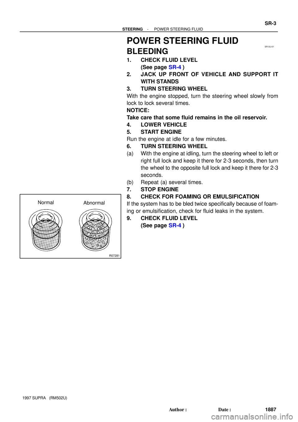
8. CHECK FOR FOAMING OR EMULSIFICATION
If the system has to be bled twice specifically because of foam-
ing or emulsification, check for fluid leaks in the system.
9. CHECK FLUID LEVEL
(See page SR-4)
Page 1573 of 1807

or less
Engine Idling Engine Stopped SR-4
- STEERINGPOWER STEERING FLUID
1888 Author�: Date�:
1997 SUPRA (RM502U)
INSPECTION
1. C")
SR13V-01
R00441
R07281
Normal Abnormal
R10552
5 mm (0.20 in.)
or less
Engine Idling Engine Stopped SR-4
- STEERINGPOWER STEERING FLUID
1888 Author�: Date�:
1997 SUPRA (RM502U)
INSPECTION
1. CHECK FLUID LEVEL
(a) Keep the vehicle level.
With the engine stopped, check the fluid level in the oil
reservoir.
If necessary, add fluid.
Fluid: ATF DEXRON® II or III
HINT:
Check that the fluid level is within the HOT LEVEL range on the
dipstick of the reservoir cap. If the fluid is cold, check that it is
within the COLD LEVEL range.
(b) Start the engine and run it at idle.
(c) Turn the steering wheel from lock to lock several times to
boost fluid temperature.
Fluid temperature: 80°C (176°F)
(d) Check for foaming or emulsification.
If there is foaming or emulsification, bleed power steering sys-
tem.
(See page SR-3)
(e) With the engine idling, measure the fluid level in the oil
reservoir.
(f) Stop the engine.
(g) Wait a few minutes and remeasure the fluid level in the
reservoir.
Maximum fluid level rise: 5mm (0.20 in.)
If a problem is found, bleed power steering system.
(See page SR-3)
(h) Check the fluid level.
Page 1574 of 1807
Z16580
INSSTSST
OUTPressure Feed Tube
Attachment
PS Vane Pump 2JZ-GE:
2JZ-GTE:
Attachment Attachment PS Vane Pump Attachment
Pressure Feed Tube
- STEERINGPOWER STEERING FLUID
SR-5
1889 Author�: Date�:
1997 SUPRA (RM502U)
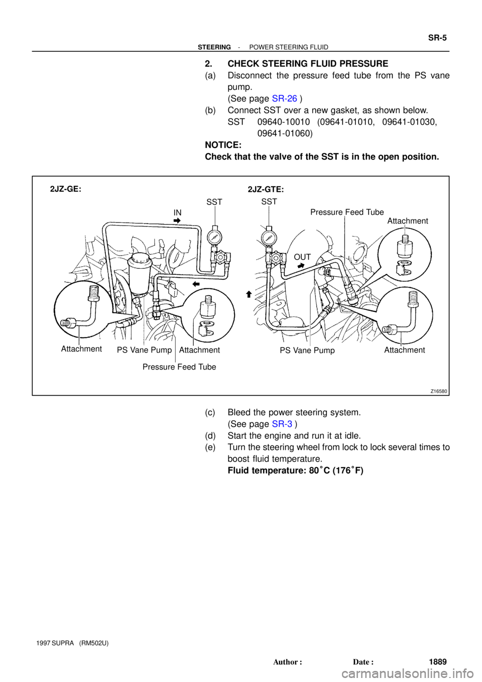
2. CHECK STEERING FLUID PRESSURE
(a) Disconnect the pressure feed tube from the PS vane
pump.
(See page SR-26)
(b) Connect SST over a new gasket, as shown below.
SST 09640-10010 (09641-01010, 09641-01030,
09641-01060)
NOTICE:
Check that the valve of the SST is in the open position.
(c) Bleed the power steering system.
(See page SR-3)
(d) Start the engine and run it at idle.
(e) Turn the steering wheel from lock to lock several times to
boost fluid temperature.
Fluid temperature: 80°C (176°F)
Page 1575 of 1807

Z15498
PS GearOil
Reservior
PS Vane
Pump Closed
SST
Z15499
PS GearOil
Reservior
PS Vane
Pump
SST Open
Z15500
PS GearOil
Reservior
PS Vane
Pump
SST Open SR-6
- STEERINGPOWER STEERING FLUID
1890 Author�: Date�:
1997 SUPRA (RM502U)
(f) With the engine idling, close the valve of the SST and ob-
serve the reading on the SST.
Minimum fluid pressure:
7,355 kPa (75 kgf.cm
2, 1,067 psi)
NOTICE:
�Do not keep the valve closed for more than 10 se-
conds.
�Do not let the fluid temperature become too high.
(g) With the engine idling, open the valve fully.
(h) Measure the fluid pressure at engine speeds of 1,000 rpm
and 3,000 rpm.
Difference fluid pressure:
490 kPa (5 kgf.cm
2, 71 psi) or less
NOTICE:
Do not turn the steering wheel.
(i) With the engine idling and valve fully opened, turn the
wheel to full lock.
Minimum fluid pressure:
7,355 kpa (75 kgf,cm
2, 1,067 psi)
NOTICE:
�Do not maintain lock position for more than 10 se-
conds.
�Do not let the fluid temperature become too high.
(j) Disconnect the SST.
(k) Connect the pressure feed tube.
(See page SR-34)
(l) Bleed the power steering system.
(See page SR-3)
Page 1583 of 1807

11. Tilt Lever Side:
REMOVE TILT LEV")
Z13448
Hexagon
Wrench
R09495
Nut
Bolt
SST Plate WasherTilt No.2 Bolt
R09496
SST
SST SR-14
- STEERINGTILT STEERING COLUMN
1898 Author�: Date�:
1997 SUPRA (RM502U)
11. Tilt Lever Side:
REMOVE TILT LEVER RETAINER
Remove the nut and E-ring.
12. Tilt Sub Lever Side:
REMOVE TILT LEVER RETAINER
(a) Using a hexagon wrench (4 mm) to hold the tilt memory
bolt, remove the nut.
(b) Remove the nut, washer and bolt.
(c) Remove the nut, E-ring and spacer.
(d) Remove the collar.
(e) Temporarily install the bolt, washer and nut.
13. REMOVE 2 TILT PAWL STOPPERS
14. REMOVE 2 TILT PAWLS
(a) Remove the bolt, nut and washer.
(b) Remove the tilt lever assembly set bolt.
15. REMOVE TILT LEVER, TILT SUB LEVER, TILT LEVER
ASSEMBLY AND TILT LEVER LOCK SHAFT
16. REMOVE TILT MEMORY BOLT AND SQUARE NUT
Using a hexagon wrench (4 mm), remove the bolt.
17. REMOVE COLUMN UPPER TUBE WITH MAIN SHAFT
ASSEMBLY
(a) Set SST, the nut (10 mm nominal diameter, 1.25 mm
pitch), plate washer (36 mm outer diameter) and bolt (10
mm nominal diameter, 1.25 mm pitch, 50 mm length) to
the tilt No.2 bolt, as shown.
SST 09910-00015 (09911-0001 1, 09912-00010)
Reference:
Nut 90170-10004
Plate washer 90201-10201
Bolt 91111-51050
(b) Remove the 2 tilt No.2 bolts by using the sliding hammer
on SST.
(c) Remove the upper tube with the shaft assembly from the
column lower tube.
18. REMOVE MAIN SHAFT ASSEMBLY
(a) Using SST, compress the compression spring.
SST 09950-40010 (09957-04010, 09958-04010)
NOTICE:
Do not bend the universal joint of the main shaft assembly
more than 20°.
(b) Using a snap ring expander, remove the snap ring.
(c) Remove the main shaft assembly from the upper tube.
(d) Remove the compression spring, thrust collar and bear-
ing from the main shaft.