Page 1585 of 1807

SR140-01
R11204
R11203
Screwdriver
Key Cylinder
R01835
SR-16
- STEERINGTILT STEERING COLUMN
1900 Author�: Date�:
1997 SUPRA (RM502U)
INSPECTION
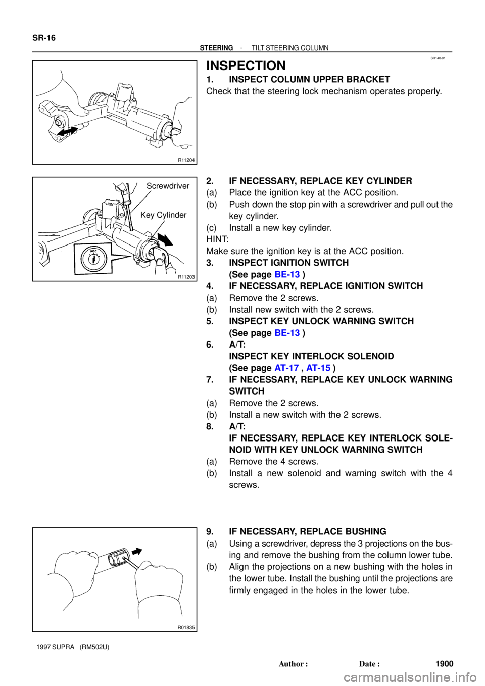
1. INSPECT COLUMN UPPER BRACKET
Check that the steering lock mechanism operates properly.
2. IF NECESSARY, REPLACE KEY CYLINDER
(a) Place the ignition key at the ACC position.
(b) Push down the stop pin with a screwdriver and pull out the
key cylinder.
(c) Install a new key cylinder.
HINT:
Make sure the ignition key is at the ACC position.
3. INSPECT IGNITION SWITCH
(See page BE-13)
4. IF NECESSARY, REPLACE IGNITION SWITCH
(a) Remove the 2 screws.
(b) Install new switch with the 2 screws.
5. INSPECT KEY UNLOCK WARNING SWITCH
(See page BE-13)
6. A/T:
INSPECT KEY INTERLOCK SOLENOID
(See page AT-17, AT-15)
7. IF NECESSARY, REPLACE KEY UNLOCK WARNING
SWITCH
(a) Remove the 2 screws.
(b) Install a new switch with the 2 screws.
8. A/T:
IF NECESSARY, REPLACE KEY INTERLOCK SOLE-
NOID WITH KEY UNLOCK WARNING SWITCH
(a) Remove the 4 screws.
(b) Install a new solenoid and warning switch with the 4
screws.
9. IF NECESSARY, REPLACE BUSHING
(a) Using a screwdriver, depress the 3 projections on the bus-
ing and remove the bushing from the column lower tube.
(b) Align the projections on a new bushing with the holes in
the lower tube. Install the bushing until the projections are
firmly engaged in the holes in the lower tube.
Page 1587 of 1807

R07550
Z13449
Nut
Bolt
R07552
SR-18
- STEERINGTILT STEERING COLUMN
1902 Author�: Date�:
1997 SUPRA (RM502U)
(b) Using a vise, press in the 2 tilt No.2 bolts.
6. INSTALL TILT MEMORY BOLT AND SQUARE NUT
(a) Apply sealant to 2 or 3 threads of the bolt.
Sealant:
Part No. 08833-00080, THREE BOND 1344,
LOCTITE 242 or equivalent.
(b) Using a hexagon wrench (4 mm), install the shorter side
of the bolt to the nut.
Torque: 6.4 N´m (65 kgf´cm, 56 in.´lbf)
7. INSTALL TILT LEVER LOCK SHAFT, TILT LEVER AS-
SEMBLY, TILT SUB LEVER AND TILT LEVER
Temporarily tighten the tilt lever assembly set bolt.
8. INSTALL 2 TILT PAWLS
(a) Temporarily install the bolt, washer and nut.
HINT:
Install the pin of the pawl into the long hole of the tilt lever / tilt
sub lever.
(b) Torque the tilt lever assembly set bolt.
Torque: 4.7 N´m (48 kgf´cm, 42 in.´lbf)
9. ENGAGE AND ADJUST 2 TILT PAWLS
(a) Engage the tilt sub lever side pawl to the center of the
ratchet.
(b) Using a spanner (17 mm), while turning the collar, com-
pletely engage the tilt lever side pawl to the ratchet.
NOTICE:
�Do not turn the collar after the tilt lever side pawl is en-
gaged.
�Keep the bolt and nut temporarily tightened.
Page 1590 of 1807

SR142-01
W02982
R07283
Matchmarks A
B
R05740
Red Mark
- STEERINGTILT STEERING COLUMN
SR-21
1905 Author�: Date�:
1997 SUPRA (RM502U)
INSTALLATION
1. INSTALL STEERING COLUMN ASSEMBLY
(a) Torque the 4 column assembly set nuts.
Torque: 25 N´m (260 kgf´cm, 19 ft´lbf)
(b) Connect the connectors.
(c) Install the brake pedal return spring.
(d) Tighten the hole cover clamp.
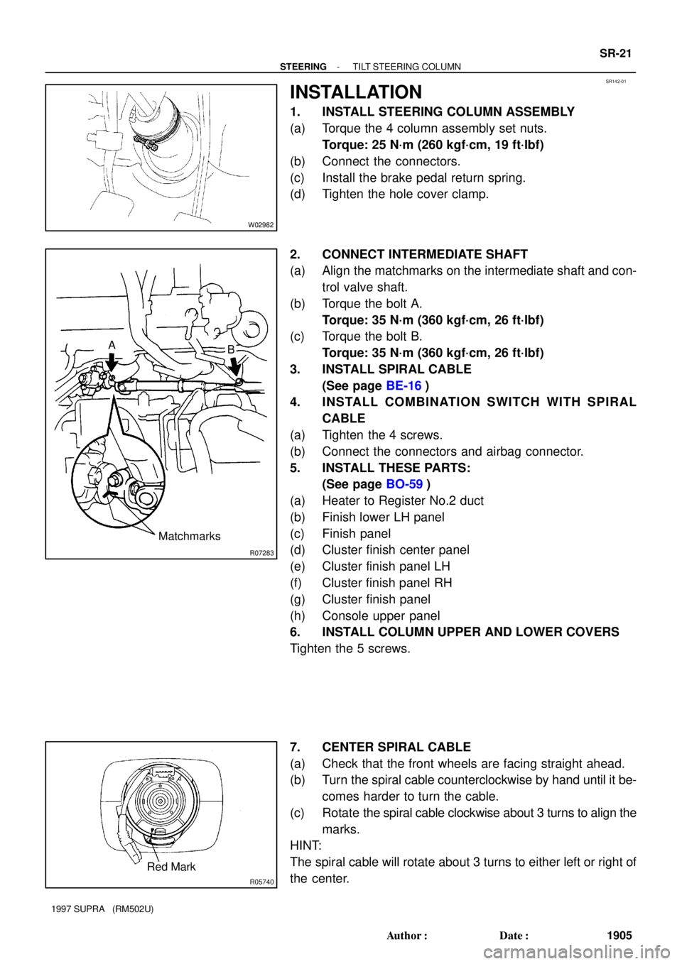
2. CONNECT INTERMEDIATE SHAFT
(a) Align the matchmarks on the intermediate shaft and con-
trol valve shaft.
(b) Torque the bolt A.
Torque: 35 N´m (360 kgf´cm, 26 ft´lbf)
(c) Torque the bolt B.
Torque: 35 N´m (360 kgf´cm, 26 ft´lbf)
3. INSTALL SPIRAL CABLE
(See page BE-16)
4. INSTALL COMBINATION SWITCH WITH SPIRAL
CABLE
(a) Tighten the 4 screws.
(b) Connect the connectors and airbag connector.
5. INSTALL THESE PARTS:
(See page BO-59)
(a) Heater to Register No.2 duct
(b) Finish lower LH panel
(c) Finish panel
(d) Cluster finish center panel
(e) Cluster finish panel LH
(f) Cluster finish panel RH
(g) Cluster finish panel
(h) Console upper panel
6. INSTALL COLUMN UPPER AND LOWER COVERS
Tighten the 5 screws.
7. CENTER SPIRAL CABLE
(a) Check that the front wheels are facing straight ahead.
(b) Turn the spiral cable counterclockwise by hand until it be-
comes harder to turn the cable.
(c) Rotate the spiral cable clockwise about 3 turns to align the
marks.
HINT:
The spiral cable will rotate about 3 turns to either left or right of
the center.
Page 1595 of 1807

SR144-01
R06091
R07429
R07432
SR-26
- STEERINGPOWER STEERING VANE PUMP
1910 Author�: Date�:
1997 SUPRA (RM502U)
REMOVAL
1. REMOVE ENGINE UNDER COVER
Remove the 10 screws.
2. REMOVE BATTERY
(a) Disconnect the 2 terminals.
(b) Remove the bolt, nut and battery clamp.
(c) Remove the battery cover.
(d) Remove the battery and battery carrier.
3. 2JZ-GTE:
REMOVE AIR HOSE No.5
4. REMOVE DRIVE BELT
Loosen the drive belt tension by turning the drive belt tensioner
clockwise, and remove the drive belt.
5. 2JZ-GTE:
DISCONNECT OIL RESERVOIR TO PUMP HOSE
Remove the clip and disconnect the hose.
NOTICE:
Take care not to spill fluid on the A/C compressor rotor.
6. 2JZ-GE:
DISCONNECT RETURN TUBE
NOTICE:
Take care not to spill fluid on the A/C compressor rotor.
7. 2JZ-GTE:
REMOVE VANE PUMP PULLEY
Using SST to stop the pulley rotating, remove the nut.
SST 09960-10010 (09962-01000, 09963-01000)
8. REMOVE PRESSURE FEED TUBE
Using a spanner (24 mm) to hold the pressure port union, re-
move the union bolt and gasket.
9. REMOVE PS VANE PUMP ASSEMBLY
Remove the 2 pump assembly set bolts.
Page 1603 of 1807

SR148-01
Z09176
Stopper
R07429
R06091
SR-34
- STEERINGPOWER STEERING VANE PUMP
1918 Author�: Date�:
1997 SUPRA (RM502U)
INSTALLATION
1. INSTALL PS VANE PUMP ASSEMBLY
Torque the 2 bolts.
Torque:
RH side bolt: 39 N´m (400 kgf´cm, 29 ft´lbf)
LH side bolt: 58 N´m (590 kgf´cm, 42 ft´lbf)
2. CONNECT PRESSURE FEED TUBE
Using a spanner (24 mm) to hold the pressure port union,
torque the union bolt with a new gasket.
HINT:
Make sure that the stopper of the tube is touching the PS vane
pump assembly as shown, before torquing the union bolt.
Torque: 49 N´m (500 kgf´cm, 36 ft´lbf)
3. 2JZ-GTE:
INSTALL VANE PUMP PULLEY
Using SST to stop the pulley rotating, torque the nut.
SST 09960-10010 (09962-01000, 09663-01000)
Torque: 43 N´m (440 kgf´cm, 32 ft´lbf)
4. 2JZ-GE:
CONNECT RETURN TUBE
5. 2JZ-GTE:
CONNECT OIL RESERVOIR TO PUMP HOSE
Connect the hose and install the clip.
6. INSTALL DRIVE BELT
Loosen the drive belt tension by turning the drive belt tensioner
clockwise, and install the drive belt.
7. 2JZ-GTE:
INSTALL AIR HOSE No.5
8. INSTALL BATTERY
(a) Install the battery carrier and battery.
(b) Install the battery cover.
(c) Install the battery clamp with bolt and nut.
(d) Connect the 2 terminals.
9. INSTALL ENGINE UNDER COVER
Install the 10 screws.
10. BLEED POWER STEERING SYSTEM
(See page SR-3)
Page 1608 of 1807

SR14B-01
R06961
SST
R07510
SST
SR4371Matchmarks
Z06090
Chisel
R07107SST
- STEERINGPOWER STEERING GEAR
SR-39
1923 Author�: Date�:
1997 SUPRA (RM502U)
DISASSEMBLY
NOTICE:
When using a vise, do not overtighten it.
1. SECURE PS GEAR ASSEMBLY IN VISE
Using SST, secure the gear assembly in a vise.
SST 09612-00012
2. REMOVE 2 TURN PRESSURE TUBES
(a) Remove the union bolt and 2 gaskets.
(b) Using SST, remove the tube.
SST 09633-00020
(c) Remove the 2 union seats from the rack housing.
3. REMOVE RH AND LH TIE ROD ENDS AND LOCK
NUTS
Place matchmarks on the tie rod end and rack end, and loosen
the lock nut.
4. REMOVE RH AND LH CLIPS, RACK BOOTS AND
CLAMPS
NOTICE:
�Be careful not to damage the boot.
�Mark the RH and LH boots.
5. REMOVE RH AND LH RACK ENDS AND CLAW WASH-
ERS
(a) Using a chisel and a hammer, unstake the washer.
NOTICE:
Avoid any impact to the steering rack.
(b) Using a spanner (22 mm) to hold the steering rack and us-
ing SST, remove the rack end.
SST 09922-10010
NOTICE:
�Use SST 09922-10010 in the direction shown in the il-
lustration.
�Mark the RH and LH rack ends.
Page 1609 of 1807

R07108
SST
R07439
SST
Self-Locking
Nut
R07336
Vinyl Tape
R07099
Vinyl Tape SR-40
- STEERINGPOWER STEERING GEAR
1924 Author�: Date�:
1997 SUPRA (RM502U)
6. REMOVE RACK GUIDE SPRING CAP LOCK NUT
Using SST, remove the nut.
SST 09922-10010
NOTICE:
Use SST 09922-10010 in the direction shown in the illustra-
tion.
7. REMOVE RACK GUIDE SPRING CAP, RACK GUIDE
SPRING, RACK GUIDE AND RACK GUIDE SEAT
Using a hexagon wrench (24 mm), remove the cap.
8. REMOVE RACK HOUSING CAP
9. REMOVE SELF- LOCKING NUT, BEARING AND
SPACER
Using SST to stop the control valve shaft rotating, remove the
nut.
SST 09616-00010
10. REMOVE DUST COVER
11. REMOVE CONTROL VALVE HOUSING WITH CON-
TROL VALVE ASSEMBLY
(a) To prevent oil seal lip damage, wind vinyl tape on the ser-
rated part of the control valve shaft.
(b) Using a hexagon wrench (6 mm), remove the 2 bolts.
(c) Remove the O-ring from the housing.
12. REMOVE CONTROL VALVE ASSEMBLY
Using a plastic hammer, tap out the control valve.
NOTICE:
Be careful not to damage the oil seal lip.
13. REMOVE CYLINDER END STOPPER AND 2 SPACERS
Using snap ring pliers, remove the snap ring from the rack hous-
ing.
Page 1611 of 1807

SR14C-01
R10072
R07288
A
B
C
BearingSST
R07109
Cutouts
SST
Oil Seal
W00209
Press
SST
Oil Seal
SST
W00210
SST
Bearing SR-42
- STEERINGPOWER STEERING GEAR
1926 Author�: Date�:
1997 SUPRA (RM502U)
INSPECTION
NOTICE:
When using a vise, do not overtighten it.
1. INSPECT STEERING RACK
(a) Using a dial indicator, check the rack for runout and for
teeth wear or damage.
Maximum runout: 0.30mm (0.018 in.)
(b) Check the back surface for wear or damage.
2. IF NECESSARY, REPLACE OIL SEAL AND BEARING
(a) Set SST to the rack housing, as shown.
SST 09612-30012
(b) Turn A clockwise and engage the tips of C on the bearing.
(c) Using a spanner (8 mm), keep A fixed while turning nut B
clockwise, and remove the bearing.
NOTICE:
Be careful not to damage the rack housing.
(d) Using SST, remove the oil seal from the rack housing.
SST 09612-30012
NOTICE:
Be careful not to damage the rack housing.
HINT:
When using SST, apply the tips of SST to the cutouts in the rack
housing.
(e) Coat a new oil seal lip with power steering fluid.
(f) Using SST, press in the oil seal.
SST 09950-60010 (09951-00280, 09951-00390,
09952-06010), 09950-70010 (09951-07100)
NOTICE:
Make sure to install the oil seal facing the correct direction.
(g) Using SST, press in the bearing.
SST 09950-60010 (09951-00460),
09950-70010 (09951-07100)