Page 1460 of 3342
3. Compressor
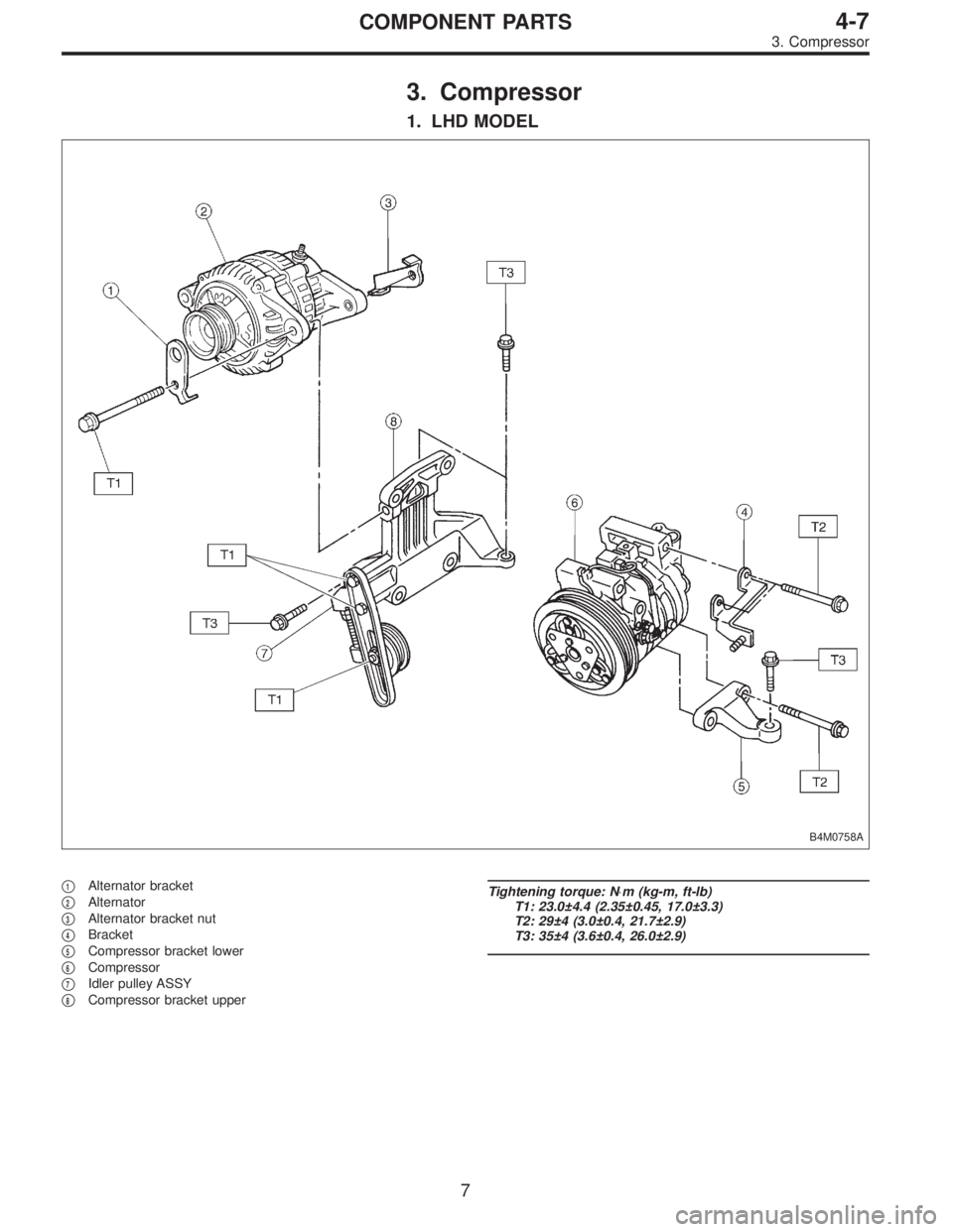
1. LHD MODEL
B4M0758A
�1Alternator bracket
�
2Alternator
�
3Alternator bracket nut
�
4Bracket
�
5Compressor bracket lower
�
6Compressor
�
7Idler pulley ASSY
�
8Compressor bracket upper
Tightening torque: N⋅m (kg-m, ft-lb)
T1: 23.0±4.4 (2.35±0.45, 17.0±3.3)
T2: 29±4 (3.0±0.4, 21.7±2.9)
T3: 35±4 (3.6±0.4, 26.0±2.9)
7
4-7COMPONENT PARTS
3. Compressor
Page 1461 of 3342
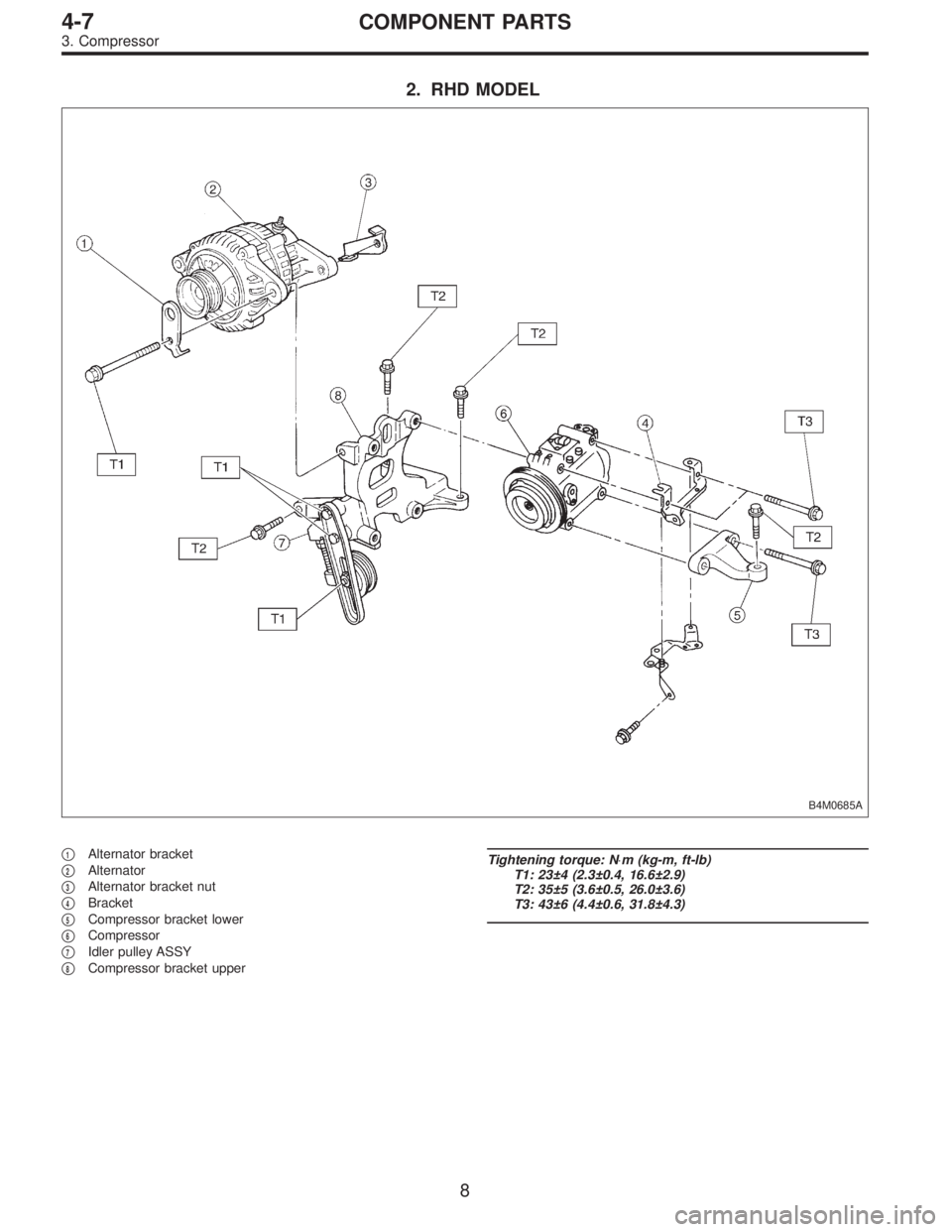
2. RHD MODEL
B4M0685A
�1Alternator bracket
�
2Alternator
�
3Alternator bracket nut
�
4Bracket
�
5Compressor bracket lower
�
6Compressor
�
7Idler pulley ASSY
�
8Compressor bracket upper
Tightening torque: N⋅m (kg-m, ft-lb)
T1: 23±4 (2.3±0.4, 16.6±2.9)
T2: 35±5 (3.6±0.5, 26.0±3.6)
T3: 43±6 (4.4±0.6, 31.8±4.3)
8
4-7COMPONENT PARTS
3. Compressor
Page 1465 of 3342

3. Tools and Equipment
The following section provides information about the tools
and equipment that will be necessary to properly service
the A/C system.
Since equipment may vary slightly depending on the
manufacturer, it is important to always read and follow the
manufacturer’s instructions.
CAUTION:
When working on vehicles with the HFC-134a system,
only use HFC-134a specified tools and parts. Do not
mix with CFC-12 tools and parts. If HFC-134a and
CFC-12 refrigerant or compressor oil is mixed, poor
lubrication will result and the compressor itself may be
destroyed.
In order to help prevent mixing HFC-134a and CFC-12
parts and liquid, the tool and screw type and the type
of service valves used are different. The gas leak
detectors for the HFC-134a and CFC-12 systems must
also not be interchanged.
HFC-134a CFC-12
Tool & screw type Millimeter size Inch size
Valve type Quick joint type Screw-in type
Tools and Equipment Description
�WRENCH
VariousWRENCHESwill be required to service any A/C
system. A 7 to 40 N⋅m (0.7 to 4.1 kg-m, 5 to 30 ft-lb) torque
wrench with various crowfoot wrenches will be needed. Open
end or flare nut wrenches will be needed for back-up on the
tube and hose fittings.
G4M0571
�APPLICATOR BOTTLE
A smallAPPLICATOR BOTTLEis recommended to apply
refrigerant oil to the various parts. They can be obtained at a
hardware or drug store.
G4M0572
12
4-7SERVICE PROCEDURE
3. Tools and Equipment
Page 1468 of 3342
 Avoid unnecessary handling and contact of O-rings with
your hands, since even clea")
4. O-ring Connections
1. GENERAL
The following points should be kept in mind when assem-
bling O-ring connections.
1) Avoid unnecessary handling and contact of O-rings with
your hands, since even clean fingers contain body acids,
which can contaminate the O-ring surface.
2) Do not handle O-rings with gloves, shop towels, etc.,
since lint particles may cling to the O-ring, possibly caus-
ing a leak upon assembly.
3) Always lubricate O-rings before assembly to allow the
O-ring to seat itself properly.
4) Be certain to use torque wrenches when tightening
O-ring fittings, because overtightening can not only dam-
age the O-ring, but it can distort the tube end as well.
G4M0581
2. REMOVE PROTECTIVE SEALS
Just prior to making the connection, remove the protective
seals.
CAUTION:
If for any reason you have to stop before making a
connection, recap the tube, component or fitting.
G4M0582
Visually inspect the O-ring surface, the O-ring mating
surface, the threads and the connection points. If a defec-
tive part is found, replace it.
The O-ring must sit square against the tube bead. If
necessary, slide the O-ring into proper positionwith clean
hands.
15
4-7SERVICE PROCEDURE
4. O-ring Connections
Page 1469 of 3342

G4M0583
3. LUBRICATE THE COMPONENTS
For lubrication of the components, use only refrigerant oil
as described in the appropriate service manual. Apply oil
from an oil squirt gun or other closed container. Do not use
your finger to spread the oil over the O-ring.
Apply a small amount of refrigerant oil to the top and sides
of the O-ring. The area covered by oil should include the
O-ring and the tube bead.
G4M0584
4. TORQUE THE FITTING
Using a back-up wrench in conjunction with a calibrated
torque wrench, torque the connection to the midrange of
the specification.
After completion of torquing, use a clean shop towel to
remove any excess oil from the connection or any oil that
may have dripped on the vehicle body or other parts.
CAUTION:
If a leak is suspected after torquing, do not retighten
or retorque the connection. Instead, disassemble the
connection, remove the O-ring, and inspect the O-ring,
threads, joints and seating surfaces.
16
4-7SERVICE PROCEDURE
4. O-ring Connections
Page 1494 of 3342
 Disconnect battery negative terminal.
2) Disconnect harness connector from fan motor.
3) Remove condenser fan bolt from radiator.
4)")
B4M0102A
15. Condenser Fan Assembly
A: REMOVAL AND INSTALLATION
1) Disconnect battery negative terminal.
2) Disconnect harness connector from fan motor.
3) Remove condenser fan bolt from radiator.
4) Pull condenser fan assembly.
5) Install the condenser fan assembly in the reverse order
of removal.
Tightening torque:
T: 7.4±2.0 N⋅m (0.75±0.2 kg-m, 5.4±1.4 ft-lb)
B4M0103
B4M0764
16. Flexible Hose
A: REMOVAL AND INSTALLATION
1) Disconnect battery negative terminal.
2) Discharge refrigerant using refrigerant recovery system.
3) Remove low-pressure hose.
(1) Remove hose attaching bolts.
CAUTION:
Plug the opening to prevent foreign matter from get-
ting in.
(2) Disconnect the connector at evaporator module.
4) Remove high-pressure hose.
(1) Disconnect hose attaching bolt (compressor side).
(2) Disconnect hose attaching bolt (condenser side).
CAUTION:
Plug the opening to prevent foreign matter from get-
ting in.
5) Installation is in the reverse order of removal.
6) Charge refrigerant.
38
4-7SERVICE PROCEDURE
15. Condenser Fan Assembly - 16. Flexible Hose
Page 1495 of 3342
 Disconnect battery negative terminal.
2) Disconnect harness connector from fan motor.
3) Remove condenser fan bolt from radiator.
4)")
B4M0102A
15. Condenser Fan Assembly
A: REMOVAL AND INSTALLATION
1) Disconnect battery negative terminal.
2) Disconnect harness connector from fan motor.
3) Remove condenser fan bolt from radiator.
4) Pull condenser fan assembly.
5) Install the condenser fan assembly in the reverse order
of removal.
Tightening torque:
T: 7.4±2.0 N⋅m (0.75±0.2 kg-m, 5.4±1.4 ft-lb)
B4M0103
B4M0764
16. Flexible Hose
A: REMOVAL AND INSTALLATION
1) Disconnect battery negative terminal.
2) Discharge refrigerant using refrigerant recovery system.
3) Remove low-pressure hose.
(1) Remove hose attaching bolts.
CAUTION:
Plug the opening to prevent foreign matter from get-
ting in.
(2) Disconnect the connector at evaporator module.
4) Remove high-pressure hose.
(1) Disconnect hose attaching bolt (compressor side).
(2) Disconnect hose attaching bolt (condenser side).
CAUTION:
Plug the opening to prevent foreign matter from get-
ting in.
5) Installation is in the reverse order of removal.
6) Charge refrigerant.
38
4-7SERVICE PROCEDURE
15. Condenser Fan Assembly - 16. Flexible Hose
Page 1532 of 3342
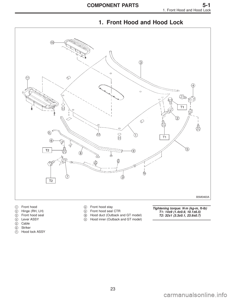
1. Front Hood and Hood Lock
B5M0460A
�1Front hood
�
2Hinge (RH, LH)
�
3Front hood seal
�
4Lever ASSY
�
5Cable
�
6Striker
�
7Hood lock ASSY�
8Front hood stay
�
9Front hood seal CTR
�
10Hood duct (Outback and GT model)
�
11Hood inner (Outback and GT model)
Tightening torque: N⋅m (kg-m, ft-lb)
T1: 14±9 (1.4±0.9, 10.1±6.5)
T2: 32±1 (3.3±0.1, 23.9±0.7)
23
5-1COMPONENT PARTS
1. Front Hood and Hood Lock