Page 254 of 3342
 Set the vehicle onto the lift.
2) Disconnect batter")
7. Valve Clearance
A: INSPECTION
1. 2200 cc MODEL
CAUTION:
Inspection and adjustment of valve clearance should
be performed while engine is cold.
1) Set the vehicle onto the lift.
2) Disconnect battery ground cable.
3) Remove timing belt cover (RH).
B2M1225A
4) Remove rocker cover.
�When inspecting #1 and #3 cylinders;
(1) Disconnect connector from mass air flow sensor.
B2M1226A
(2) Loosen clamp which connects air intake duct to air
intake chamber.
(3) Remove the two clips from air cleaner upper cover.
CAUTION:
Before installing air cleaner upper cover, align hole(s)
with protruding portions of air cleaner lower case, then
secure upper cover.
(4) Disconnect blow-by hose from air intake duct.
B2M1227
(5) Remove air intake duct and air cleaner upper cover
as a unit.
(6) Remove air cleaner element.
(7) Disconnect spark plug cords from spark plugs (#1
and #3 cylinders).
(8) Remove under cover (RH).
(9) Place suitable container under the vehicle.
(10) Disconnect PCV hose from rocker cover (RH).
(11) Remove bolts, then remove rocker cover (RH).
9
2-2
7. Valve Clearance
Page 256 of 3342
 Similar to measurement procedures used for #1
cylinder, measure #2, #3 and #4 cylinder valve clearances.
NOTE:
�Be sure to set cylinder pistons to their respective top
dead centers on comp")
B2M1230A
8) Similar to measurement procedures used for #1
cylinder, measure #2, #3 and #4 cylinder valve clearances.
NOTE:
�Be sure to set cylinder pistons to their respective top
dead centers on compression stroke before measuring
valve clearances.
�To set #3, #2 and #4 cylinder pistons to their top dead
centers on compression stroke, turn crankshaft pulley
clockwise 90°at a time starting with arrow mark on right-
hand camshaft sprocket facing up.
9) After inspection, install the related parts in the reverse
order of removal.
2. 2500 cc MODEL
CAUTION:
Inspection and adjustment of valve clearance should
be performed while engine is cold.
1) Set the vehicle onto the lift.
2) Disconnect battery ground cable.
3) Remove canister.
4) Remove one bolt which secures timing belt cover (RH).
5) Lift-up the vehicle.
6) Remove under cover (RH).
7) Remove canister bracket.
8) Loosen remaining bolts which secure timing belt cover
(RH), then remove belt cover.
9) Lower the vehicle.
B2M1225A
10) Remove rocker cover.
�When inspecting #1 and #3 cylinders;
(1) Disconnect connector from mass air flow sensor.
11
2-2
7. Valve Clearance
Page 260 of 3342
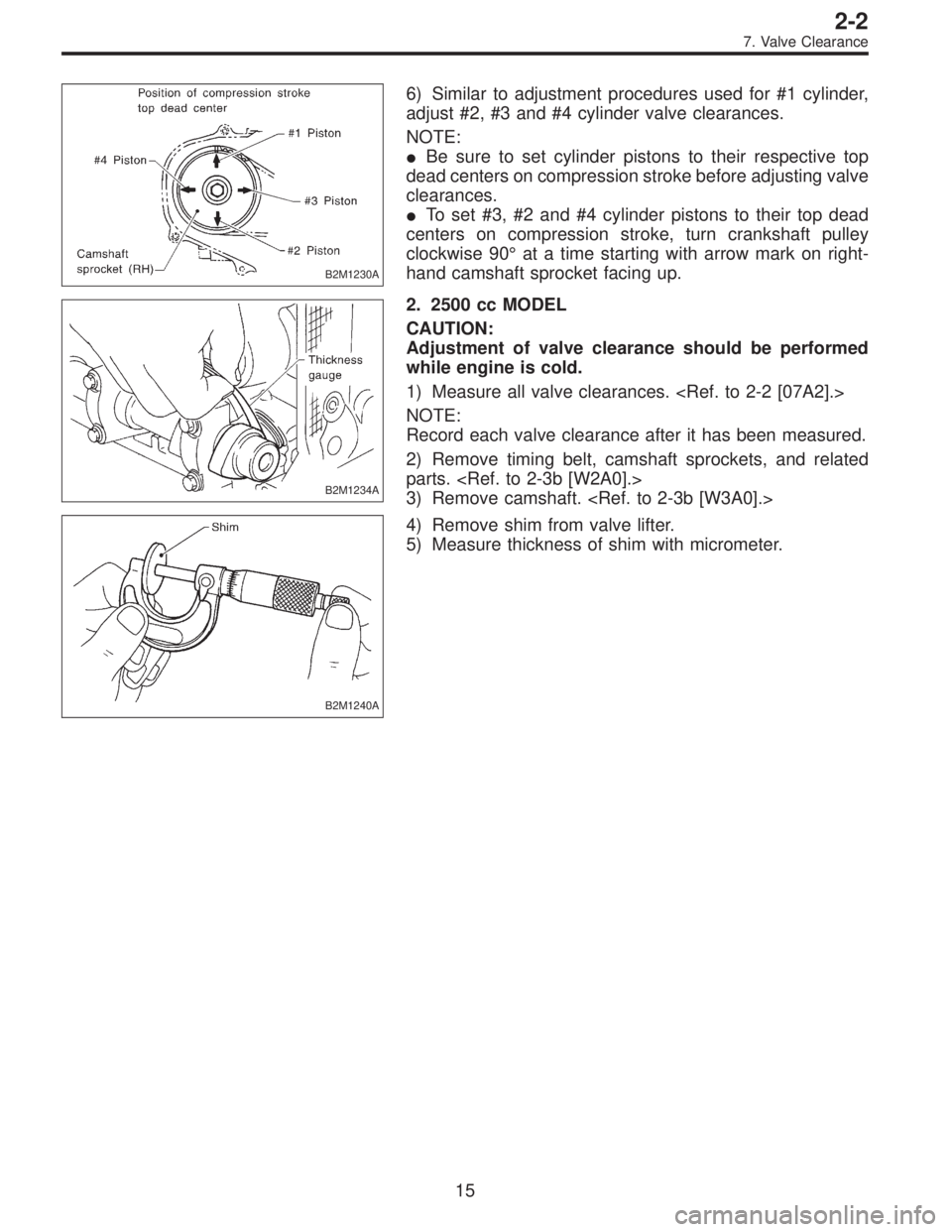
B2M1230A
6) Similar to adjustment procedures used for #1 cylinder,
adjust #2, #3 and #4 cylinder valve clearances.
NOTE:
�Be sure to set cylinder pistons to their respective top
dead centers on compression stroke before adjusting valve
clearances.
�To set #3, #2 and #4 cylinder pistons to their top dead
centers on compression stroke, turn crankshaft pulley
clockwise 90°at a time starting with arrow mark on right-
hand camshaft sprocket facing up.
B2M1234A
2. 2500 cc MODEL
CAUTION:
Adjustment of valve clearance should be performed
while engine is cold.
1) Measure all valve clearances.
NOTE:
Record each valve clearance after it has been measured.
2) Remove timing belt, camshaft sprockets, and related
parts.
3) Remove camshaft.
B2M1240A
4) Remove shim from valve lifter.
5) Measure thickness of shim with micrometer.
15
2-2
7. Valve Clearance
Page 261 of 3342
 Select a shim of suitable thickness using measured
valve clearance and shim thickness, using the following
table.
Unit: mm
Intake valve:S=(V+T)�0.20
Exhaust valve:S=(V+T)�0.25
S: Shim thickness to")
6) Select a shim of suitable thickness using measured
valve clearance and shim thickness, using the following
table.
Unit: mm
Intake valve:S=(V+T)�0.20
Exhaust valve:S=(V+T)�0.25
S: Shim thickness to be used
V: Measured valve clearance
T: Shim thickness required
Part No. Thickness mm (in)
13218AC290 2.33 (0.0917)
13218AC300 2.34 (0.0921)
13218AC310 2.35 (0.0925)
13218AC320 2.36 (0.0929)
13218AC330 2.37 (0.0933)
13218AC340 2.38 (0.0937)
13218AC350 2.39 (0.0941)
13218AC360 2.40 (0.0945)
13218AC370 2.41 (0.0949)
13218AC380 2.42 (0.0953)
13218AC390 2.43 (0.0957)
13218AC400 2.44 (0.0961)
13218AC410 2.45 (0.0965)
13218AC420 2.46 (0.0969)
13218AC430 2.47 (0.0972)
13218AC440 2.48 (0.0976)
13218AC450 2.49 (0.0980)
13218AC460 2.50 (0.0984)
13218AC470 2.51 (0.0988)Part No. Thickness mm (in)
13218AC480 2.52 (0.0992)
13218AC490 2.53 (0.0996)
13218AC500 2.54 (0.1000)
13218AC510 2.55 (0.1004)
13218AC520 2.56 (0.1008)
13218AC530 2.57 (0.1012)
13218AC540 2.58 (0.1016)
13218AC550 2.59 (0.1020)
13218AC560 2.60 (0.1024)
13218AC570 2.61 (0.1028)
13218AC580 2.62 (0.1031)
13218AC590 2.63 (0.1035)
13218AC600 2.64 (0.1039)
13218AC610 2.65 (0.1043)
13218AC620 2.66 (0.1047)
13218AC630 2.67 (0.1051)
13218AC640 2.68 (0.1055)
13218AC650 2.69 (0.1059)
7) Set suitable shim selected in step 6) to valve lifter.
8) Install camshaft.
9) Install camshaft sprockets, timing belt and related parts.
NOTE:
At this point, do not install rocker cover.
16
2-2
7. Valve Clearance
Page 263 of 3342
1. Engine
A: SPECIFICATIONS
EngineModel2200 cc
TypeHorizontally opposed, liquid cooled, 4-cylinder, 4-stroke
gasoline engine
Valve arrangement Belt driven, single over-head camshaft, 4-valve/cylinder
Bore x Stroke mm (in) 96.9 x 75.0 (3.815 x 2.953)
Displacement cm
3(cu in) 2,212 (135.0)
Compression ratio9.7
Compression pressure
(at 200 — 300 rpm) kPa (kg/cm
2, psi)1,079 — 1,275
(11.0 — 13.0, 156 — 185)
Number of piston rings Pressure ring: 2, Oil ring: 1
Intake valve timingOpening 4° BTDC
Closing 52° ABDC
Exhaust valve timingOpening 48° BBDC
Closing 12° ATDC
Valve clearanceIntake mm (in) 0.20±0.02 (0.0079±0.0008)
Exhaust mm (in) 0.25±0.02 (0.0098±0.0008)
Idling speed
[At neutral position on MT, or
“P” or “N” position on AT] rpm700±100 (No load)
850±50 (A/C switch ON)
Firing order1,3,2,4
Ignition timing BTDC/rpm 14°±8°/700 (MT), 20°±8°/700 (AT)
2
2-3SPECIFICATIONS AND SERVICE DATA
1. Engine
Page 267 of 3342
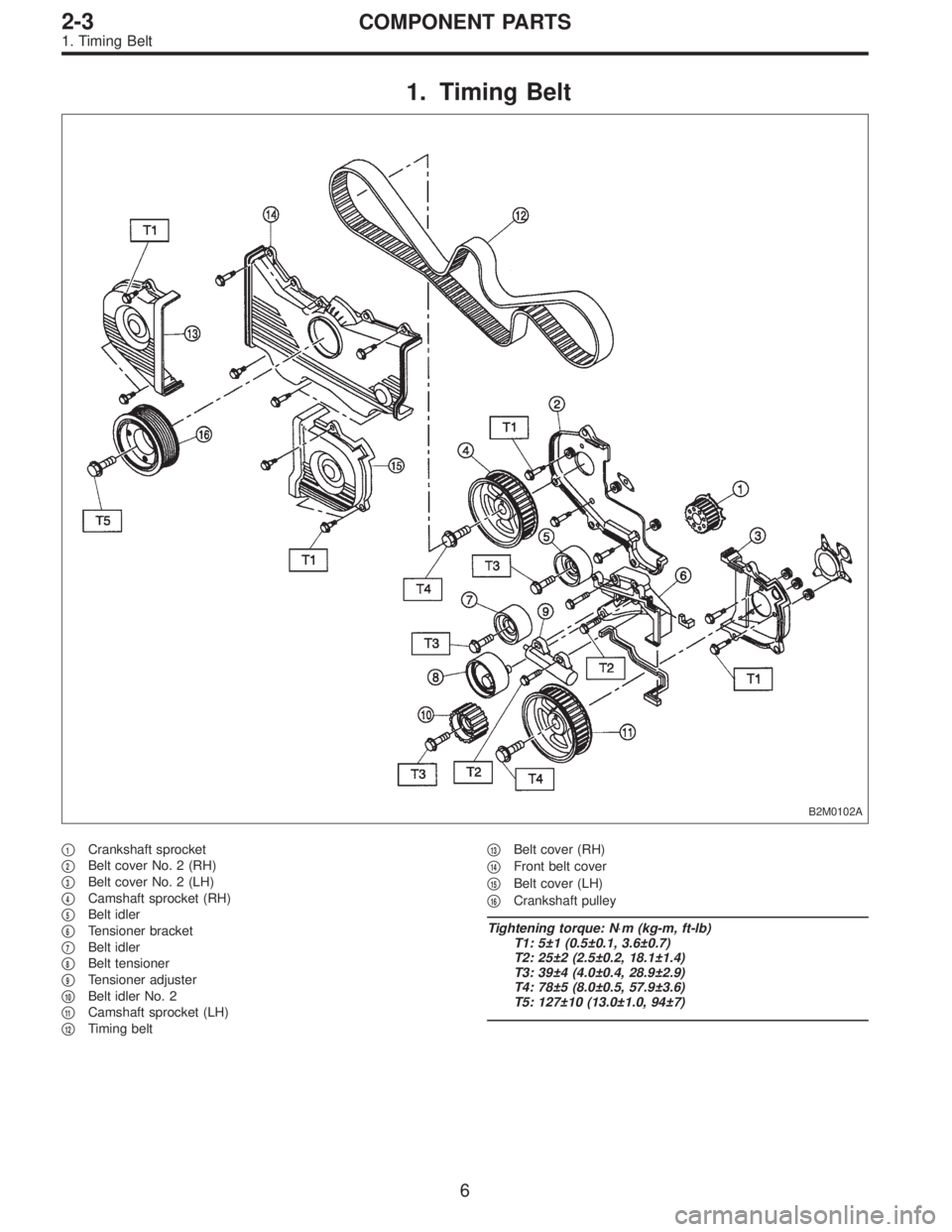
1. Timing Belt
B2M0102A
�1Crankshaft sprocket
�
2Belt cover No. 2 (RH)
�
3Belt cover No. 2 (LH)
�
4Camshaft sprocket (RH)
�
5Belt idler
�
6Tensioner bracket
�
7Belt idler
�
8Belt tensioner
�
9Tensioner adjuster
�
10Belt idler No. 2
�
11Camshaft sprocket (LH)
�
12Timing belt�
13Belt cover (RH)
�
14Front belt cover
�
15Belt cover (LH)
�
16Crankshaft pulley
Tightening torque: N⋅m (kg-m, ft-lb)
T1: 5±1 (0.5±0.1, 3.6±0.7)
T2: 25±2 (2.5±0.2, 18.1±1.4)
T3: 39±4 (4.0±0.4, 28.9±2.9)
T4: 78±5 (8.0±0.5, 57.9±3.6)
T5: 127±10 (13.0±1.0, 94±7)
6
2-3COMPONENT PARTS
1. Timing Belt
Page 272 of 3342
 Before disassembling engine, place it on ST3.
ST1 498457000 ENGINE STAND ADAPTER RH
ST2 498457100 ENGINE STAND ADAPTER LH
ST3 499817000 ENGINE STAND
2) All parts shou")
G2M0106
1. General Precautions
1) Before disassembling engine, place it on ST3.
ST1 498457000 ENGINE STAND ADAPTER RH
ST2 498457100 ENGINE STAND ADAPTER LH
ST3 499817000 ENGINE STAND
2) All parts should be thoroughly cleaned, paying special
attention to the engine oil passages, pistons and bearings.
3) Rotating parts and sliding parts such as piston, bearing
and gear should be coated with oil prior to assembly.
4) Be careful not to let oil, grease or coolant contact the
timing belt, clutch disc and flywheel.
5) All removed parts, if to be reused, should be reinstalled
in the original positions and directions.
6) Gaskets and lock washers must be replaced with new
ones. Liquid gasket should be used where specified to
prevent leakage.
7) Bolts, nuts and washers should be replaced with new
ones as required.
8) Even if necessary inspections have been made in
advance, proceed with assembly work while making
rechecks.
2. Hydraulic Lash Adjuster
A: INSPECTION
1) Disconnect blow-by hose from rocker cover.
2) Remove spark plug cap.
B2M0413A
3) Remove left and right rocker covers.
CAUTION:
Before removing left rocker cover, disconnect battery
cables and generator cable.
11
2-3SERVICE PROCEDURE
1. General Precautions - 2. Hydraulic Lash Adjuster
Page 273 of 3342
 Before disassembling engine, place it on ST3.
ST1 498457000 ENGINE STAND ADAPTER RH
ST2 498457100 ENGINE STAND ADAPTER LH
ST3 499817000 ENGINE STAND
2) All parts shou")
G2M0106
1. General Precautions
1) Before disassembling engine, place it on ST3.
ST1 498457000 ENGINE STAND ADAPTER RH
ST2 498457100 ENGINE STAND ADAPTER LH
ST3 499817000 ENGINE STAND
2) All parts should be thoroughly cleaned, paying special
attention to the engine oil passages, pistons and bearings.
3) Rotating parts and sliding parts such as piston, bearing
and gear should be coated with oil prior to assembly.
4) Be careful not to let oil, grease or coolant contact the
timing belt, clutch disc and flywheel.
5) All removed parts, if to be reused, should be reinstalled
in the original positions and directions.
6) Gaskets and lock washers must be replaced with new
ones. Liquid gasket should be used where specified to
prevent leakage.
7) Bolts, nuts and washers should be replaced with new
ones as required.
8) Even if necessary inspections have been made in
advance, proceed with assembly work while making
rechecks.
2. Hydraulic Lash Adjuster
A: INSPECTION
1) Disconnect blow-by hose from rocker cover.
2) Remove spark plug cap.
B2M0413A
3) Remove left and right rocker covers.
CAUTION:
Before removing left rocker cover, disconnect battery
cables and generator cable.
11
2-3SERVICE PROCEDURE
1. General Precautions - 2. Hydraulic Lash Adjuster