Page 1433 of 3342
G4M0329
D: ASSEMBLY
1. BRAKE AND CLUTCH PEDAL
1) Attach stop light switch, etc. to pedal bracket tempo-
rarily.
2) Clean inside of bores of clutch pedal and brake pedal,
apply grease, and set bushings into bores.
3) Align bores of pedal bracket, clutch pedal and brake
pedal, attach brake pedal return spring and clutch pedal
effort reducing spring (vehicle with hill holder), and then
install pedal bolt.
Tightening torque:
T2: 29±7 N⋅m (3.0±0.7 kg-m, 21.7±5.1 ft-lb)
NOTE:
Clean up inside of bushings and apply grease before
installing spacer.
4) Set brake pedal position by adjusting position of stop
light switch.
Pedal position: L
125.9 mm (4.96 in)
Tightening torque:
T1: 8±2 N⋅m (0.8±0.2 kg-m, 5.8±1.4 ft-lb)
2. ACCELERATOR PEDAL
Clean and apply grease to spacer and inside bore of accel-
erator pedal. Install accelerator pedal onto pedal bracket.
14
4-5SERVICE PROCEDURE
1. Pedal
Page 1435 of 3342

1) Turn cruise control clutch switch lock nuts until clutch
pedal full stroke length is within specifications.
CAUTION:
Do not attempt to turn cl")
B4M1190A
F: ADJUSTMENT
1. CLUTCH PEDAL (2500 cc MODEL)
1) Turn cruise control clutch switch lock nuts until clutch
pedal full stroke length is within specifications.
CAUTION:
Do not attempt to turn clutch switch to adjust clutch
pedal full stroke length.
NOTE:
If lock nuts cannot adjust clutch pedal full stroke length to
specifications, turn master cylinder push rod to adjust it.
Specified clutch pedal full stroke: A
145—150 mm (5.71—5.91 in)
Tightening torque (Clutch switch lock nut):
8±2 N⋅m (0.8±0.2 kg-m, 5.8±1.4 ft-lb)
B4M1189A
2) Turn master cylinder push rod so that clevis pin moves
to the left and then to the right. Clevis pin must move with-
out resistance while it is rattling.
Tightening torque (Push rod lock nut):
8±2 N⋅m (0.8±0.2 kg-m, 5.8±1.4 ft-lb)
3) Depress and release clutch pedal 2 to 3 times to ensure
that clutch pedal and release fork operate smoothly. If
clutch pedal and release fork do not operate smoothly,
bleed air from clutch hydraulic system.
[W202].>
4) Measure clutch pedal full stroke length again to ensure
that it is within specifications. If it is not, repeat adjustment
procedures again from the beginning.
Specified clutch pedal full stroke:
145—150 mm (5.71—5.91 in)
16
4-5SERVICE PROCEDURE
1. Pedal
Page 1442 of 3342
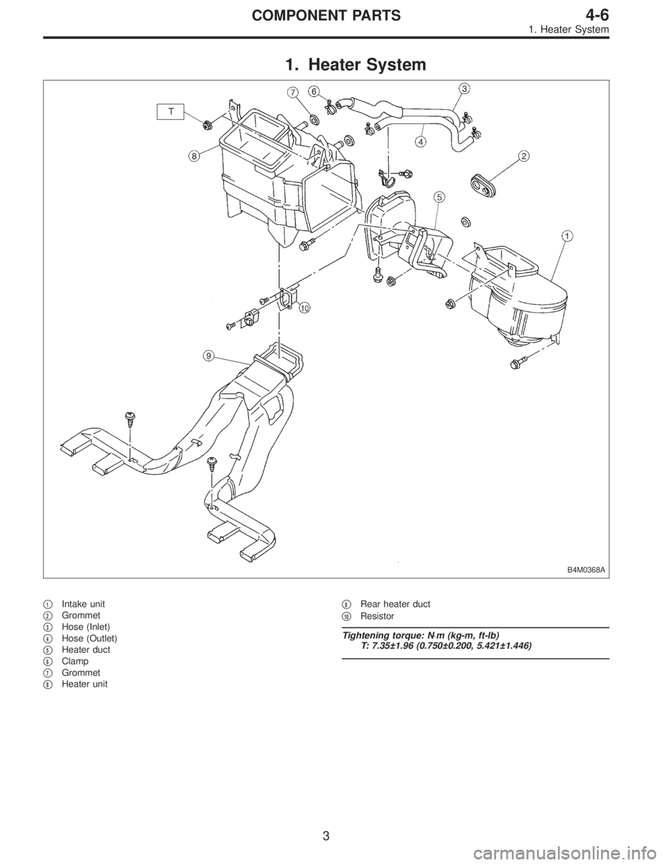
1. Heater System
B4M0368A
�1Intake unit
�
2Grommet
�
3Hose (Inlet)
�
4Hose (Outlet)
�
5Heater duct
�
6Clamp
�
7Grommet
�
8Heater unit�
9Rear heater duct
�
10Resistor
Tightening torque: N⋅m (kg-m, ft-lb)
T: 7.35±1.96 (0.750±0.200, 5.421±1.446)
3
4-6COMPONENT PARTS
1. Heater System
Page 1443 of 3342
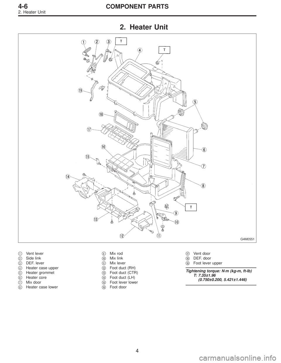
2. Heater Unit
G4M0551
�1Vent lever
�
2Side link
�
3DEF. lever
�
4Heater case upper
�
5Heater grommet
�
6Heater core
�
7Mix door
�
8Heater case lower�
9Mix rod
�
10Mix link
�
11Mix lever
�
12Foot duct (RH)
�
13Foot duct (CTR)
�
14Foot duct (LH)
�
15Foot lever lower
�
16Foot door�
17Vent door
�
18DEF. door
�
19Foot lever upper
Tightening torque: N⋅m (kg-m, ft-lb)
T: 7.35±1.96
(0.750±0.200, 5.421±1.446)
4
4-6COMPONENT PARTS
2. Heater Unit
Page 1444 of 3342
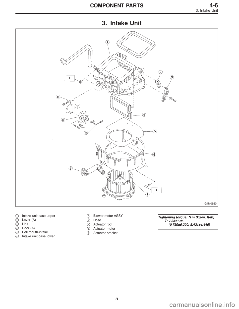
3. Intake Unit
G4M0920
�1Intake unit case upper
�
2Lever (A)
�
3Link
�
4Door (A)
�
5Bell mouth-intake
�
6Intake unit case lower�
7Blower motor ASSY
�
8Hose
�
9Actuator rod
�
10Actuator motor
�
11Actuator bracket
Tightening torque: N⋅m (kg-m, ft-lb)
T: 7.35±1.96
(0.750±0.200, 5.421±1.446)
5
4-6COMPONENT PARTS
3. Intake Unit
Page 1456 of 3342
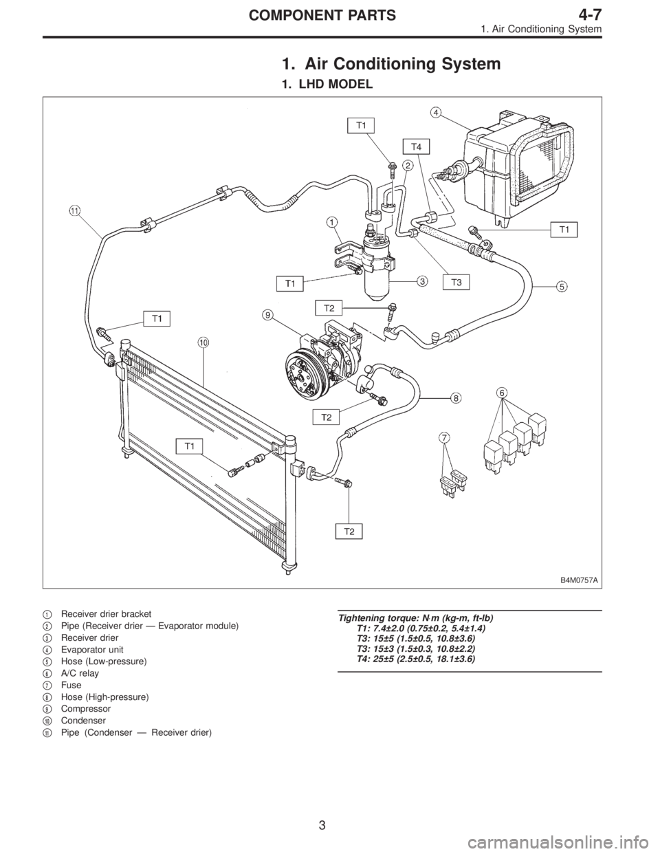
1. Air Conditioning System
1. LHD MODEL
B4M0757A
�1Receiver drier bracket
�
2Pipe (Receiver drier—Evaporator module)
�
3Receiver drier
�
4Evaporator unit
�
5Hose (Low-pressure)
�
6A/C relay
�
7Fuse
�
8Hose (High-pressure)
�
9Compressor
�
10Condenser
�
11Pipe (Condenser—Receiver drier)
Tightening torque: N⋅m (kg-m, ft-lb)
T1: 7.4±2.0 (0.75±0.2, 5.4±1.4)
T3: 15±5 (1.5±0.5, 10.8±3.6)
T3: 15±3 (1.5±0.3, 10.8±2.2)
T4: 25±5 (2.5±0.5, 18.1±3.6)
3
4-7COMPONENT PARTS
1. Air Conditioning System
Page 1457 of 3342
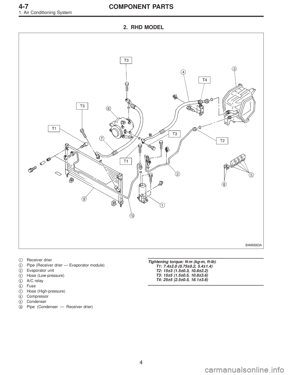
2. RHD MODEL
B4M0683A
�1Receiver drier
�
2Pipe (Receiver drier—Evaporator module)
�
3Evaporator unit
�
4Hose (Low-pressure)
�
5A/C relay
�
6Fuse
�
7Hose (High-pressure)
�
8Compressor
�
9Condenser
�
10Pipe (Condenser—Receiver drier)
Tightening torque: N⋅m (kg-m, ft-lb)
T1: 7.4±2.0 (0.75±0.2, 5.4±1.4)
T2: 15±3 (1.5±0.3, 10.8±2.2)
T3: 15±5 (1.5±0.5, 10.8±3.6)
T4: 25±5 (2.5±0.5, 18.1±3.6)
4
4-7COMPONENT PARTS
1. Air Conditioning System
Page 1458 of 3342
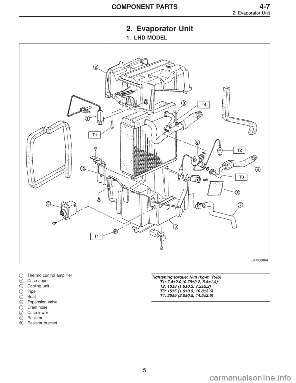
2. Evaporator Unit
1. LHD MODEL
B4M0086A
�1Thermo control amplifier
�
2Case upper
�
3Cooling unit
�
4Pipe
�
5Seat
�
6Expansion valve
�
7Drain hose
�
8Case lower
�
9Resistor
�
10Resistor bracket
Tightening torque: N⋅m (kg-m, ft-lb)
T1: 7.4±2.0 (0.75±0.2, 5.4±1.4)
T2: 10±3 (1.0±0.3, 7.2±2.2)
T3: 15±5 (1.5±0.5, 10.8±3.6)
T4: 20±5 (2.0±0.5, 14.5±3.6)
5
4-7COMPONENT PARTS
2. Evaporator Unit
 Attach stop light switch, etc. to pedal bracket tempo-
rarily.
2) Clean inside of bores of clutch pedal and brake pedal,
apply grease, and set bushings")