Page 2989 of 3342

: Are the tone wheel installation bolts tight-
ened securely?
: Go to step10L10.
: Tighten tone wheel")
10L9CHECK INSTALLATION OF TONE
WHEEL.
Tightening torque:
13±3 N⋅m (1.3±0.3 kg-m, 9±2.2 ft-lb)
: Are the tone wheel installation bolts tight-
ened securely?
: Go to step10L10.
: Tighten tone wheel installation bolts securely.
G4M0700
10L10
CHECK ABS SENSOR GAP.
Measure tone wheel to pole piece gap over entire perim-
eter of the wheel.
: Is the gap within the specifications shown
in the following table?
SpecificationsFront wheel Rear wheel
0.9—1.4 mm
(0.035—0.055 in)0.7—1.2 mm
(0.028—0.047 in)
G4M0701
: Go to step10L11.
: Adjust the gap.
NOTE:
Adjust the gap using spacer (Part No. 26755AA000). If
spacers cannot correct the gap, replace worn sensor or
worn tone wheel.
10L11
CHECK OSCILLOSCOPE.
: Is an oscilloscope available?
: Go to step10L12.
: Go to step10L13.
10L12
CHECK ABS SENSOR SIGNAL.
1) Raise all four wheels of ground.
2) Turn ignition switch OFF.
3) Connect the oscilloscope to the connector (F1) or con-
nector (B100) in accordance with trouble code.
4) Turn ignition switch ON.
11 3
4-4dBRAKES [ABS 5.3i TYPE]
10. Diagnostics Chart with Select Monitor
Page 2996 of 3342

10M1CHECK IF THE WHEELS HAVE TURNED
FREELY FOR A LONG TIME.
: Check if the wheels have been turned freely
for more than one minute, such as when the
vehicle is jacked-up, under full-lock corner-
ing or when tire is not in contact with road
surface.
: The ABS is normal. Erase the trouble code.
NOTE:
When the wheels turn freely for a long time, such as when
the vehicle is towed or jacked-up, or when steering wheel
is continuously turned all the way, this trouble code may
sometimes occur.
: Go to step10M2.
10M2
CHECK TIRE SPECIFICATIONS.
Turn ignition switch to OFF.
: Are the tire specifications correct?
: Go to step10M3.
: Replace tire.
10M3
CHECK WEAR OF TIRE.
: Is the tire worn excessively?
: Replace tire.
: Go to step10M4.
10M4
CHECK TIRE PRESSURE.
: Is the tire pressure correct?
: Go to step10M5.
: Adjust tire pressure.
10M5CHECK INSTALLATION OF ABS SEN-
SOR.
Tightening torque:
32±10 N⋅m (3.3±1.0 kg-m, 24±7 ft-lb)
: Are the ABS sensor installation bolts tight-
ened securely?
: Go to step10M6.
: Tighten ABS sensor installation bolts securely.
120
4-4dBRAKES [ABS 5.3i TYPE]
10. Diagnostics Chart with Select Monitor
Page 2997 of 3342

: Are the tone wheel installation bolts tight-
ened securely?
: Go to step10M7.
: Tighten tone wheel")
10M6CHECK INSTALLATION OF TONE
WHEEL.
Tightening torque:
13±3 N⋅m (1.3±0.3 kg-m, 9±2.2 ft-lb)
: Are the tone wheel installation bolts tight-
ened securely?
: Go to step10M7.
: Tighten tone wheel installation bolts securely.
G4M0700
10M7
CHECK ABS SENSOR GAP.
Measure tone wheel to pole piece gap over entire perim-
eter of the wheel.
: Is the gap within the specifications shown
in the following table?
SpecificationsFront wheel Rear wheel
0.9—1.4 mm
(0.035—0.055 in)0.7—1.2 mm
(0.028—0.047 in)
G4M0701
: Go to step10M8.
: Adjust the gap.
NOTE:
Adjust the gap using spacer (Part No. 26755AA000). If
spacers cannot correct the gap, replace worn sensor or
worn tone wheel.
10M8
CHECK OSCILLOSCOPE.
: Is an oscilloscope available?
: Go to step10M9.
: Go to step10M10.
10M9
CHECK ABS SENSOR SIGNAL.
1) Raise all four wheels of ground.
2) Turn ignition switch OFF.
3) Connect the oscilloscope to the connector (F1) or con-
nector (B100) in accordance with trouble code.
4) Turn ignition switch ON.
121
4-4dBRAKES [ABS 5.3i TYPE]
10. Diagnostics Chart with Select Monitor
Page 3195 of 3342
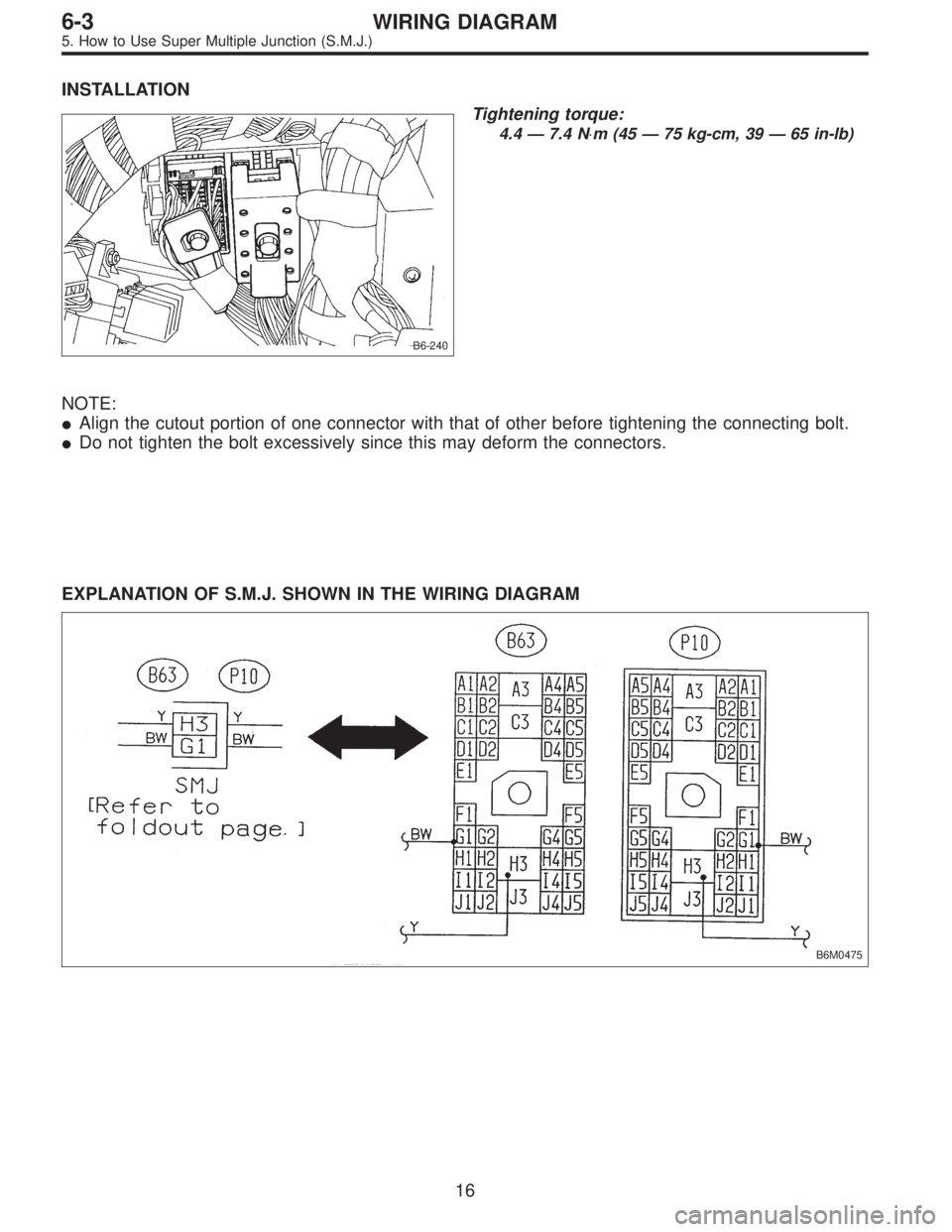
INSTALLATION
B6-240
Tightening torque:
4.4 — 7.4 N⋅m (45 — 75 kg-cm, 39 — 65 in-lb)
NOTE:
�Align the cutout portion of one connector with that of other before tightening the connecting bolt.
�Do not tighten the bolt excessively since this may deform the connectors.
EXPLANATION OF S.M.J. SHOWN IN THE WIRING DIAGRAM
B6M0475
16
6-3WIRING DIAGRAM
5. How to Use Super Multiple Junction (S.M.J.)
Page 3331 of 3342

�In this manual, the following symbols are used.
*: Selective part
�: Replacement part
: Should be lubricated with oil.
: Should be lubricated with grease.
: Sealing point
: Tightening torque
�WARNING, CAUTION, NOTE
�WARNING: Indicates the item which must be observed precisely during performance of maintenance ser-
vices in order to avoid injury to the mechanics and other persons.
�CAUTION: Indicates the item which must be followed precisely during performance of maintenance ser-
vices so as to avoid damage and breakage to the vehicle and its parts and components.
�NOTE: Indicates the hints, knacks, etc. which make the maintenance job easier.
�SPECIAL TOOLS
When any special tool is required to perform the job, it is identified by“ST”in the applicable illustration and its
part number is shown in the manual.
M1H0120
1. Procedures for adjusting backlash
1) Set steering wheel to the straight-ahead position.
2) Remove the exhaust pipe
3) Loosen the lock nut with ST.
�
{ST1 921650000 STEERING GEARBOX WRENCH
ST2 921550000 STEERING GEARBOX WRENCH
Description
(of job method)
Shows the part name
Shows the part number
Tells that two kinds of special tools are required.
When two or more kinds of special tools are required to do
a job, they are identified by ST1, ST2,......respectively.
�
��
5