Page 58 of 3342
4-4d
[rsBO]
BRAKES
[ABS
5
.31
TYPE]
8
.
Diagnostics
Chart
with
Trouble
Code
by
ABS
Warning
Light
B
:
TROUBLE
CODE
21
(FRONT
RH)
C
:
TROUBLE
CODE
23
(FRONT
LH)
D
:
TROUBLE
CODE
25
(REAR
RH)
E
:
TROUBLE
CODE
27
(REAR
LH)
-
ABNORMAL
ABS
SENSOR
(OPEN
CIRCUIT
OR
INPUT
VOLTAGE
TOO
HIGH)
-
DIAGNOSIS
:
"
Faulty
ABS
sensor
(Broken
wire,
input
voltage
too
high)
Faulty
harness
connector
TROUBLE
SYMPTOM
:
*
ABS
does
notoperate
.
WIRING
DIAGRAM
:
F49
ABS
control
module
and
hydraulic
control
unit
OUTBACK
with
steproof
model
B~5
O
O
P8
OO
Ft
100
1
3
1
10
70969
4
78
Rear
ABS
sensor
LH
RearABS
sensor
RH
r----------------
I
OUTBACK
with
steproof
model
I
I
Q
I
RearABS-C~l
sensor
LH
I
I
RearABS
j
~--m
sensor
RH
I
Q
I
------------J
Front
ABS
sensorLH
Front
ABS
sensor
RH
f{9
1
345678911112131415
1116
1
17
1
18
1
19
1
2
0
2
122
4
26
7
1
28
1
29
130131
1
B4M1238
32
Page 65 of 3342
4-4d
[TSFO]
BRAKES
[ABS
5
.31
TYPE]
8
.
Diagnostics
Chart
with
Trouble
Code
by
ABS
Warning
Light
F
:
TROUBLE
CODE
22
(FRONT
RH)
G
:
TROUBLE
CODE
24
(FRONT
LH)
H
:
TROUBLE
CODE
26
(REAR
RH)
I
:
TROUBLE
CODE
28
(REAR
LH)
-
ABNORMAL
ABS
SENSOR
(ABNORMAL
ABS
SENSOR
SIGNAL)
-
DIAGNOSIS
:
"
Faulty
ABS
sensor
signal
(noise,
irregular
signal,
etc
.)
Faulty
harness/connector
TROUBLE
SYMPTOM
:
9
ABS
does
not
operate
.
WIRING
DIAGRAM
:
f49
ABS
control
module
and
hydraulic
control
unit
OUTBACK
withstep
OO
roof
model
815
86
LL
]
Iwl
_-^
B15
~
B~~
_____===_-r
m--~~
Front
ABS
~
sensorLH
----
---
-----------
Front
ABS
-
-
----------
[Z1-1
~
sensor
RH
Twisted
~-
wire
F1Pt
OO
Twisted
wire
~
::M
Ft
100
1
3
1
10
4
78
Rear
ABS
sensorLH
RearABS
sensor
RH
I
OUTBACK
withsteproof
model
I
I
~
I
RearABS
«7
sensor
LH
II
RearABS
j
BE
sensor
RH
L-
-
-
--
-
-
-
-
-
-
-
-
-
--
-
QD
1
1
~
131415
1
§
17181911011111211
14
1
J
116117118119120121
223
24
6
2718
2930
31
B4M1238
40
Page 72 of 3342
4-4d
[Tsjo]
BRAKES
[ABS
5
.31
TYPE]
8
.
Diagnostics
Chart
with
Trouble
Code
by
ABS
Warning
Light
J
:
TROUBLE
CODE
29
-
ABNORMAL
ABS
SENSOR
SIGNAL
(ANY
ONE
OF
FOUR)
-
DIAGNOSIS
:
"
Faulty
ABS
sensor
signal
(noise,
irregular
signal,
etc
.)
Faulty
tone
wheel
"
Wheels
turning
freely
for
a
long
time
TROUBLE
SYMPTOM
:
*
ABS
does
notoperate
.
WIRING
DIAGRAM
:
F49
ABS
control
module
and
hydraulic
control
unit
OUTBACK
with
steproof
model
8~5
O
(2D
QD
CD
(
:D
LLL]
IWI
0
100
1
2
1
10
1
4
15161
7
1
8
1
RearABS
sensorLH
RearABS
sensor
RH
r-----------------i
I
OUTBACK
withsteproof
model
I
I
Q
I
RearABS
sensor
LH
II
j
~
Rear
ABS
j
sensor
RH
I
O
I
~---------------
.J
Front
ABS
sensor
LH
Front
ABS
sensor
RH
F49
r-j
i
1
2
1
5
1
4
1
5
1
6
1
7
1
8
1
9
1
1
01
11
1
12
1
131415
ll
16171819
202122
4
26
4
7
1
28
1
29
1301
31
1
B4M1238
48
Page 130 of 3342
BRAKES
[ABS
5
.31
TYPE]
[T10H0]
4-4d
10
.
Diagnostics
Chart
with
Select
Monitor
DIAGNOSIS
:
"
Faulty
ABS
sensor(Broken
wire,
input
voltage
too
high)
Faulty
harness
connector
TROUBLE
SYMPTOM
:
9
ABS
does
not
operate
.
WIRING
DIAGRAM
:
F49
ABS
control
module
and
hydraulic
control
unit
OUTBACK
with
step
roof
model
Bt5
O
O
P8
O
P8
[ft
LwI
O
8100
815
Front
ABS
sensorLH
Front
ABS
sensor
RH
Twisted
wire
Ft
Pt
OO
WEB
i
Twisted
wire
W
EB-
(2D
F1
100
F
172
-1
F3
1
F
U=
10
1
4
15161
7
1
8
Rear
ABS
sensor
LH
RearABS
sensor
RH
t
OUTBACK
with
step
roof
model
III
Rear
ABS
sensor
LH
j
~
RearABS
j
7
sensor
RH
I
~
I
L---------------J
F49
12345678910111131415
1
16
1
17
1
18
1
19
111
202122
23
4
252627
1
28
1
29
001
31
B4M1238
113
Page 140 of 3342
BRAKES
[ABS
5
.3i
TYPE]
[T10L0]4-4d
10
.
Diagnostics
Chart
withSelect
Monitor
DIAGNOSIS
:
"
Faulty
ABS
sensor
signal
(noise,
irregular
signal,
etc
.)
Faulty
harness/connector
TROUBLE
SYMPTOM
:
e
ABS
does
not
operate
.
WIRING
DIAGRAM
:
9
ABS
control
module
and
hydraulic
control
unit
Twisted
wire
Ft
0
8100
815
Front
ASS
sensorLH
RearABS
sensorLH
Rear
ABS
sensor
RH
r----------------
1
OUTBACK
with
step
roof
model
I
I
Q
I
RearABS
7
sensor
LH
I
~
III
j
~
Rear
ASS
j
sensor
RH
I
O
I
L---
.
.
.---------J
OUTBACK
with
steproof
model
B~5
O
OOOO
fl
(i~]
DO`]
478
1
10
F49
1234567891011131415
1617181920
1
212
23
4
5
26
218930
13
1
1
B4M1238
Front
ASS
sensor
RH
123
Page 149 of 3342
4-4d
[T1onno]
BRAKES
[ABS
5
.3i
TYPE]
10
.
Diagnostics
Chart
withSelect
Monitor
D
"
NEW
29
EITHER
.
SS
(FBI)
SOFT
84M0952
J
M
:
TROUBLE
CODE
29
EITHER
.
SS
SOFT
-
ABNORMAL
ABS
SENSOR
SIGNAL
(ANY
ONE
OF
FOUR)
-
DIAGNOSIS
:
"
Faulty
ABS
sensor
signal
(noise,
irregular
signal,
etc
.)
"
Faulty
tone
wheel
"
Wheels
turning
freely
for
a
long
time
TROUBLE
SYMPTOM
:
9
ABS
does
not
operate
.
WIRING
DIAGRAM
:
F19
ABS
control
module
and
hydraulic
control
unit
OUTBACK
withsteproof
model
(2D(E)(~D
QD
rll~9
No"111
100
--------
Front
ABS
F
V
----------
;
sensorl-H
LjJF
---
----------
Front
ABS
Twisted
-----
sensor
RH
wire
Ft
Pt
OO
RearABS
--~
sensor
LH
Twisted
wire
Rear
ABS
41
4
.
sensor
RH
P8
r----------------
I
OUTBACK
with
steproof
model
IIII
O~
I
RearABS
sensorLH
j
~
Rear
ABS
j
sensor
RH
I
~
I
L---------------J
Ft
8100
1121
3
1
10
45
78
f49
123456789101112131415
16171819
20
2122
23
2425
26
2728293031
B4M1238
132
Page 422 of 3342

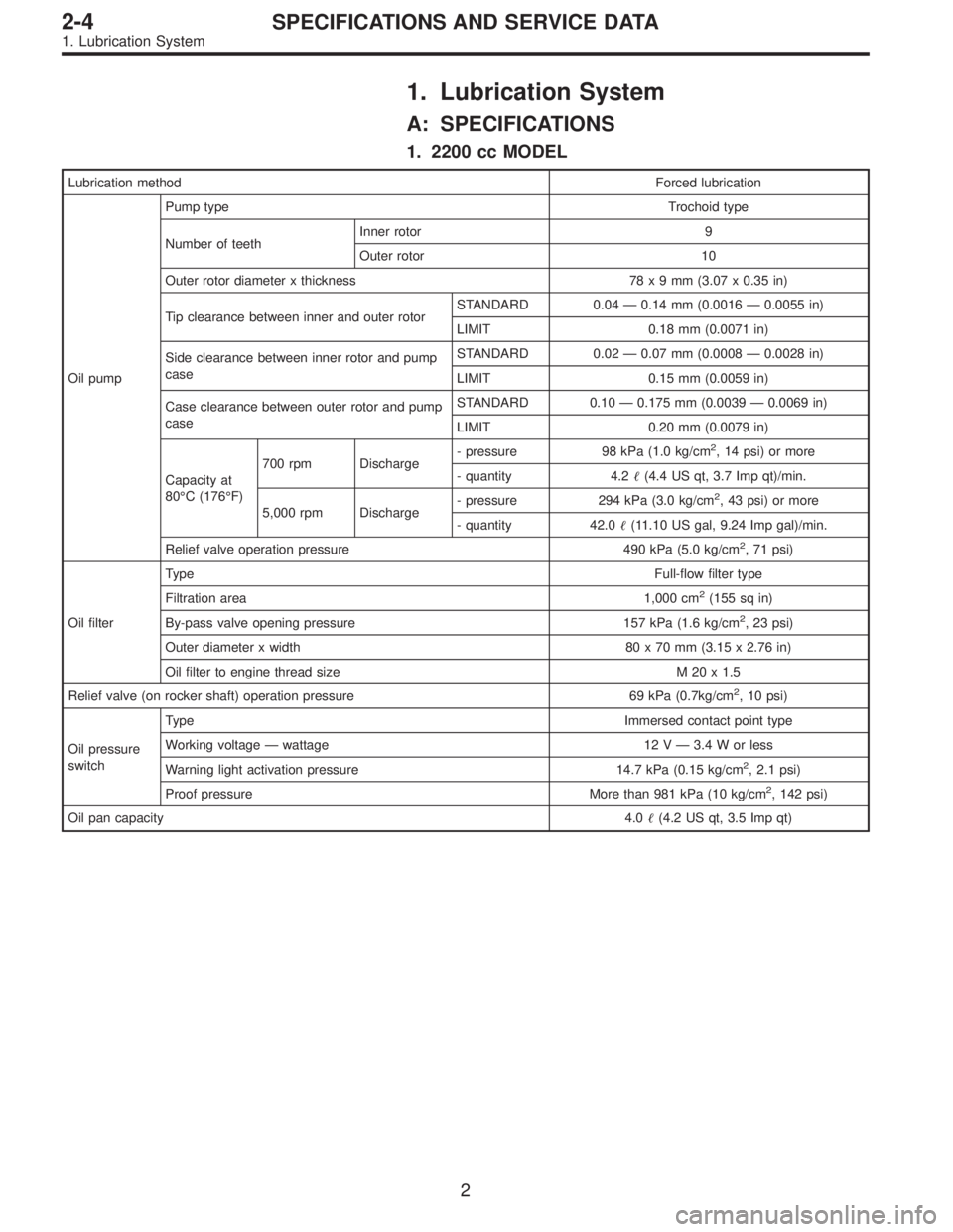
1. Lubrication System
A: SPECIFICATIONS
1. 2200 cc MODEL
Lubrication methodForced lubrication
Oil pumpPump typeTrochoid type
Number of teethInner rotor 9
Outer rotor 10
Outer rotor diameter x thickness 78x9mm(3.07 x 0.35 in)
Tip clearance between inner and outer rotorSTANDARD 0.04 — 0.14 mm (0.0016 — 0.0055 in)
LIMIT 0.18 mm (0.0071 in)
Side clearance between inner rotor and pump
caseSTANDARD 0.02 — 0.07 mm (0.0008 — 0.0028 in)
LIMIT 0.15 mm (0.0059 in)
Case clearance between outer rotor and pump
caseSTANDARD 0.10 — 0.175 mm (0.0039 — 0.0069 in)
LIMIT 0.20 mm (0.0079 in)
Capacity at
80°C (176°F)700 rpm Discharge- pressure 98 kPa (1.0 kg/cm
2, 14 psi) or more
- quantity 4.2�(4.4 US qt, 3.7 Imp qt)/min.
5,000 rpm Discharge- pressure 294 kPa (3.0 kg/cm
2, 43 psi) or more
- quantity 42.0�(11.10 US gal, 9.24 Imp gal)/min.
Relief valve operation pressure 490 kPa (5.0 kg/cm
2, 71 psi)
Oil filterTypeFull-flow filter type
Filtration area 1,000 cm
2(155 sq in)
By-pass valve opening pressure 157 kPa (1.6 kg/cm
2, 23 psi)
Outer diameter x width 80 x 70 mm (3.15 x 2.76 in)
Oil filter to engine thread size M 20 x 1.5
Relief valve (on rocker shaft) operation pressure 69 kPa (0.7kg/cm
2, 10 psi)
Oil pressure
switchTypeImmersed contact point type
Working voltage — wattage 12 V — 3.4 W or less
Warning light activation pressure 14.7 kPa (0.15 kg/cm
2, 2.1 psi)
Proof pressure More than 981 kPa (10 kg/cm
2, 142 psi)
Oil pan capacity4.0�(4.2 US qt, 3.5 Imp qt)
2
2-4SPECIFICATIONS AND SERVICE DATA
1. Lubrication System
Page 423 of 3342

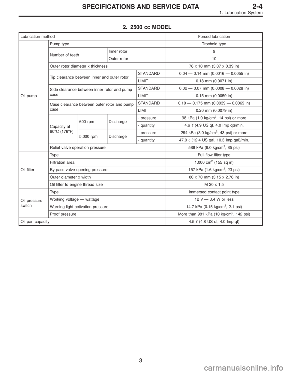
2. 2500 cc MODEL
Lubrication methodForced lubrication
Oil pumpPump typeTrochoid type
Number of teethInner rotor 9
Outer rotor 10
Outer rotor diameter x thickness 78 x 10 mm (3.07 x 0.39 in)
Tip clearance between inner and outer rotorSTANDARD 0.04—0.14 mm (0.0016—0.0055 in)
LIMIT 0.18 mm (0.0071 in)
Side clearance between inner rotor and pump
caseSTANDARD 0.02—0.07 mm (0.0008—0.0028 in)
LIMIT 0.15 mm (0.0059 in)
Case clearance between outer rotor and pump
caseSTANDARD 0.10—0.175 mm (0.0039—0.0069 in)
LIMIT 0.20 mm (0.0079 in)
Capacity at
80°C (176°F)600 rpm Discharge- pressure 98 kPa (1.0 kg/cm
2, 14 psi) or more
- quantity 4.6�(4.9 US qt, 4.0 Imp qt)/min.
5,000 rpm Discharge- pressure 294 kPa (3.0 kg/cm
2, 43 psi) or more
- quantity 47.0�(12.4 US gal, 10.3 Imp gal)/min.
Relief valve operation pressure 588 kPa (6.0 kg/cm
2, 85 psi)
Oil filterTypeFull-flow filter type
Filtration area 1,000 cm
2(155 sq in)
By-pass valve opening pressure 157 kPa (1.6 kg/cm
2, 23 psi)
Outer diameter x width 80 x 70 mm (3.15 x 2.76 in)
Oil filter to engine thread size M 20 x 1.5
Oil pressure
switchTypeImmersed contact point type
Working voltage—wattage 12 V—3.4 W or less
Warning light activation pressure 14.7 kPa (0.15 kg/cm
2, 2.1 psi)
Proof pressure More than 981 kPa (10 kg/cm
2, 142 psi)
Oil pan capacity4.5�(4.8 US qt, 4.0 Imp qt)
3
2-4SPECIFICATIONS AND SERVICE DATA
1. Lubrication System