Page 3 of 3342

R18
2
Black
B-3
Rear
speaker
RH
R19
2B-3
High-mounted
s")
8
.
Electrical
Wiring
Harness
and
Ground
Point
Connector
Connecting
to
No
.
Pole
Color
Area
No
.
Name
R17
1
Black
A-3
Rear
defogger
(Power)
R18
2
Black
B-3
Rear
speaker
RH
R19
2B-3
High-mounted
stop
light
R20
2
Blue
B-2
Trunk
room
light
R21
2
Black
B-2
Rear
speaker
LH
R22
1
Brown
B-1
Rear
door
switch
LH
R23
3
B-2
Power
antenna
R24
6B-3
R60
Trunk
lid
cord(Without
security
system)
8
B-3
R60
Trunk
lid
cord
(With
security
system)
R25
2
Black
B-4
Rear
defogger
condenser
R26
4
B-4
Rear
combination
light
RH
R27
2
B-4
Trunk
room
light
switch
R28
4
B-3
Rear
combination
light
LH
R45
6
B-4
Trailer
connector
(SUS
model)
R47
3B-3Fueltank
pressure
sensor
R60
6B-4
R24
Rear
wiring
harness
(Without
security
system)
8B-4
R24
Rear
wiring
harness
(With
security
system)
R61
3B-4
Key
switch
(Security)
R62
4B-4
Rear
finisher
light
RH
R63
2B-3
License
plate
light
R64
4B-3
Rear
finisher
light
LH
R65
1
Black
A-2
Rear
defogger(Ground)
R66
2
Black
B-4
E
High-mounted
stop
light
(Rear
spoiler)
'
:
Non-colored
3
A
B
C
D
8
.
REAR
END
WIRING
HARNESS
AND
GROUND
POINT
OF
SEDAN
1
1
2
1
3
R65
1
R17
,
R19
4
\
R66
GD
A
~
~
R45
i
O
~~`
R18
''r
~
R25
R21
~
~O
\
R22
O
R20
R24
R47
~---
R23R2g
'
:
R60
R62
o
GB-9
0
~~,
.~I
~~I)~1
B6M0104B
2
R63R26
R64R27
R61~
~
GB-9
3
[D808]
B6M0823A
4
A
B
C
D
Page 5 of 3342
![SUBARU LEGACY 1997 Service Repair Manual
BRAKES
IM13-21
4-4
13
.
Anti-lock
Brake
System
(ABS)
[5
.3i
Type]
2
.
FUNCTIONS
OF
SENSORS
AND
ACTUATORS
Name
Function
ABS
control
moduleand
hydraulic
ABSCM-
e
Calculates
and
determine
the
conditi](/manual-img/17/57434/w960_57434-4.png "SUBARU LEGACY 1997 Service Repair Manual
BRAKES
IM13-21
4-4
13
.
Anti-lock
Brake
System
(ABS)
[5
.3i
Type]
2
.
FUNCTIONS
OF
SENSORS
AND
ACTUATORS
Name
Function
ABS
control
moduleand
hydraulic
ABSCM-
e
Calculates
and
determine
the
conditi")
BRAKES
IM13-21
4-4
13
.
Anti-lock
Brake
System
(ABS)
[5
.3i
Type]
2
.
FUNCTIONS
OF
SENSORS
AND
ACTUATORS
Name
Function
ABS
control
moduleand
hydraulic
ABSCM-
e
Calculates
and
determine
the
conditionsof
the
wheels
and
body
from
control
unit
(ABSCM&H/U)
section
the
wheel
speedsand
makes
a
proper
decision
suitable
for
the
current
situation
to
control
the
hydraulic
unit
.
In
the
ABS
operation
mode,
the
module
outputs
a
cooperative
control
signal
to
the
AT
control
module
.
(AT
vehicles
only)
Whenever
the
ignition
switch
is
placed
at
ON,
the
module
makes
a
self
diagnosis
.
When
anything
wrong
is
detected,
the
module
cuts
off
the
system
.
Communicates
with
the
Subaru
select
monitor
.
H/U-section
In
the
ABS
operation
mode,
the
H/U
changes
fluid
passages
to
control
the
fluid
pressure
of
the
wheel
cylinders
in
response
to
an
instruction
from
the
ABSCM
.
The
H/U
also
constitutes
thebrake
fluid
passage
from
the
master
cylin-
der
to
the
wheel
cylinders
together
with
pipings
.
Valve
relay-
Serves
asa
power
switch
for
the
solenoid
valve
and
motor
relay
coil
in
section
response
to
an
instruction
from
the
ABSCM
.
Motor
relay-
Serves
as
a
power
switch
for
the
pump
motor
in
response
to
an
instruc-
section
tion
from
the
ABSCM
.
Wheel
speed
sensor
(ABS
sensor)
Detects
the
wheel
speed
in
terms
of
a
change
in
the
magnetic
flux
den-
sity
passingthrough
the
sensor,
converts
it
into
an
electrical
signal,
and
outputs
the
electrical
signal
to
the
ABSCM
.
Tone
wheel
Gives
a
change
in
the
magnetic
flux
density
by
the
teeth
around
the
tone
wheel
to
let
the
ABS
sensor
generate
an
electrical
signal
.
G
sensor
(AWD
vehicle
only)
Detects
a
change
in
G
in
the
longitudinal
direction
of
the
vehicle
and
outputs
it
to
the
ABSCM
in
terms
of
a
change
in
voltage
.
Stop
light
switch
Transmits
the
information
on
whether
the
brakepedal
is
depressed
or
not
to
the
ABSCM
for
use
as
a
condition
in
determining
ABS
operation
.
ABS
warning
light
Alerts
the
driver
to
an
ABS
fault
.
When
the
diagnosis
connector
and
diagnosis
terminal
are
connected,
the
light
flashes
to
indicate
a
trouble
codes
in
response
to
an
instruction
from
the
ABSCM
.
AT
control
module
(TCM)
(AT
vehicles
only)
Provides
shift
controls
(fixing
the
speed
at
3rd
or
changing
front
and
rear
wheel
transmission
characteristics
on
4WD
vehicle)
in
response
to
an
instruction
fromthe
ABSCM
.
Page 252 of 3342
G2M0088
6. Engine Oil Pressure
A: MEASUREMENT
1) Remove generator from bracket.
(1) Disconnect connector and terminal from generator.
G2M0089
(2) Remove V-belt cover.
(3) Loosen lock bolt and slider bolt, and remove V-belt
for generator.
G2M0090
(4) Remove generator lock bolt.
(5) Remove bolt which install generator on bracket.
G2M0091
2) Disconnect connector from oil pressure switch.
3) Remove oil pressure switch from engine cylinder block.
7
2-2
6. Engine Oil Pressure
Page 253 of 3342
G2M0093
4) Connect oil pressure gauge hose to cylinder block.
5) Start the engine, and measure oil pressure.
Oil pressure:
98 kPa (1.0 kg/cm
2,14 psi) or more at 800 rpm
294 kPa (3.0 kg/cm2, 43 psi) or more at 5,000 rpm
CAUTION:
�If oil pressure is out of specification, check oil
pump, oil filter and lubrication line.
�If oil pressure warning light is turned ON and oil
pressure is in specification, replace oil pressure
switch.
NOTE:
The specified data is based on an engine oil temperature
of 80°C (176°F).
6) After measuring oil pressure, install oil pressure switch.
Tightening torque:
25±3 N⋅m (2.5±0.3 kg-m, 18.1±2.2 ft-lb)
7) Install generator and V-belt in the reverse order of
removal, and adjust the V-belt deflection.
8
2-2
6. Engine Oil Pressure
Page 263 of 3342
1. Engine
A: SPECIFICATIONS
EngineModel2200 cc
TypeHorizontally opposed, liquid cooled, 4-cylinder, 4-stroke
gasoline engine
Valve arrangement Belt driven, single over-head camshaft, 4-valve/cylinder
Bore x Stroke mm (in) 96.9 x 75.0 (3.815 x 2.953)
Displacement cm
3(cu in) 2,212 (135.0)
Compression ratio9.7
Compression pressure
(at 200 — 300 rpm) kPa (kg/cm
2, psi)1,079 — 1,275
(11.0 — 13.0, 156 — 185)
Number of piston rings Pressure ring: 2, Oil ring: 1
Intake valve timingOpening 4° BTDC
Closing 52° ABDC
Exhaust valve timingOpening 48° BBDC
Closing 12° ATDC
Valve clearanceIntake mm (in) 0.20±0.02 (0.0079±0.0008)
Exhaust mm (in) 0.25±0.02 (0.0098±0.0008)
Idling speed
[At neutral position on MT, or
“P” or “N” position on AT] rpm700±100 (No load)
850±50 (A/C switch ON)
Firing order1,3,2,4
Ignition timing BTDC/rpm 14°±8°/700 (MT), 20°±8°/700 (AT)
2
2-3SPECIFICATIONS AND SERVICE DATA
1. Engine
Page 270 of 3342
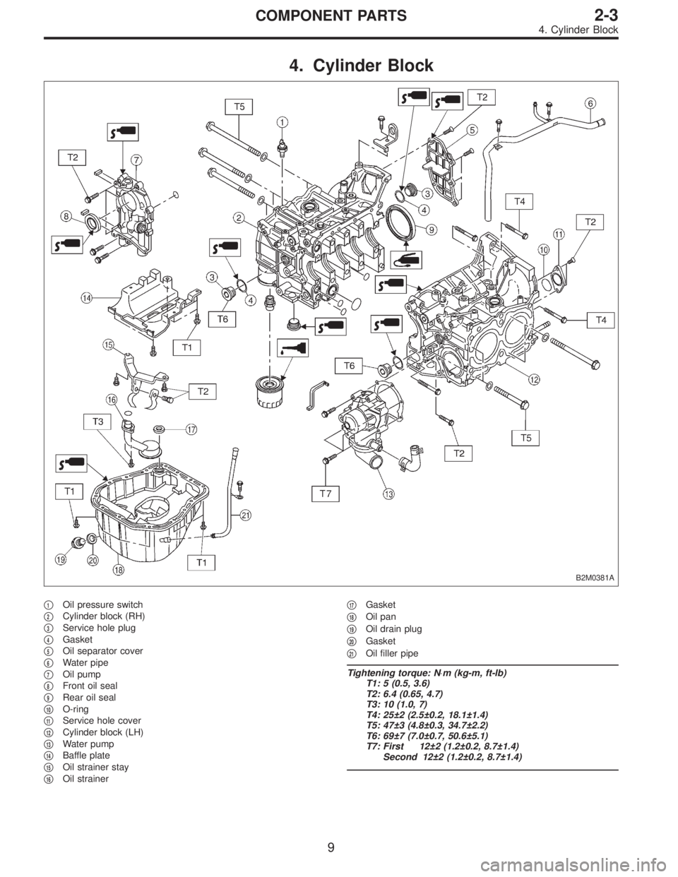
4. Cylinder Block
B2M0381A
�1Oil pressure switch
�
2Cylinder block (RH)
�
3Service hole plug
�
4Gasket
�
5Oil separator cover
�
6Water pipe
�
7Oil pump
�
8Front oil seal
�
9Rear oil seal
�
10O-ring
�
11Service hole cover
�
12Cylinder block (LH)
�
13Water pump
�
14Baffle plate
�
15Oil strainer stay
�
16Oil strainer�
17Gasket
�
18Oil pan
�
19Oil drain plug
�
20Gasket
�
21Oil filler pipe
Tightening torque: N⋅m (kg-m, ft-lb)
T1: 5 (0.5, 3.6)
T2: 6.4 (0.65, 4.7)
T3: 10 (1.0, 7)
T4: 25±2 (2.5±0.2, 18.1±1.4)
T5: 47±3 (4.8±0.3, 34.7±2.2)
T6: 69±7 (7.0±0.7, 50.6±5.1)
T7: First 12±2 (1.2±0.2, 8.7±1.4)
Second 12±2 (1.2±0.2, 8.7±1.4)
9
2-3COMPONENT PARTS
4. Cylinder Block
Page 340 of 3342
TROUBLE
Engine will not start.
Rough idle and engine stall
Low output, hesitation and poor acceleration
Surging
Engine does not return to idle.
Dieseling (Run-on)
After burning in exhaust system
Knocking
Excessive engine oil consumption
Excessive fuel consumption Starter does not turn.
Initial combustion does not occur.
Initial combustion occurs.
Engine stalls after initial combustion.
LUBRICATION SYSTEM
22 3 3�Incorrect oil pressure
2�Loosened oil pump attaching bolts and defective
gasket
2�Defective oil filter seal
2�Defective crankshaft oil seal
32�Defective rocker cover gasket
2�Loosened oil drain plug or defective gasket
2�Loosened oil pan fitting bolts or defective oil pan
COOLING SYSTEM
33221�Overheating
333�Over cooling
OTHERS
113 3�Malfunction of Evaporative Emission Control
System
21�Stuck or damaged throttle valve
322 2�Accelerator cable out of adjustment
77
2-3DIAGNOSTICS
1. Engine Trouble in General
Page 341 of 3342

2. Engine Noise
Type of sound Condition Possible cause
Regular clicking soundSound increases as engine
speed increases.Valve mechanism is defective.
�Incorrect valve clearance
�Worn valve rocker
�Worn camshaft
�Broken valve spring
Heavy and dull clankOil pressure is low.�Worn crankshaft main bearing
�Worn connecting rod bearing (big end)
Oil pressure is normal.�Loose flywheel mounting bolts
�Damaged engine mounting
High-pitched clank
(Spark knock)Sound is noticeable when
accelerating with an overload.�Ignition timing advanced
�Accumulation of carbon inside combustion chamber
�Wrong spark plug
�Improper gasoline
Clank when engine speed is
medium (1,000 to 2,000 rpm).Sound is reduced when fuel
injector connector of noisy
cylinder is disconnected.
(NOTE*)�Worn crankshaft main bearing
�Worn bearing at crankshaft end of connecting rod
Knocking sound when engine
is operating under idling speed
and engine is warm.Sound is reduced when fuel
injector connector of noisy
cylinder is disconnected.
(NOTE*)�Worn cylinder liner and piston ring
�Broken or stuck piston ring
�Worn piston pin and hole at piston end of connecting rod
Sound is not reduced if each
fuel injector connector is
disconnected in turn. (NOTE*)�Worn camshaft journal bore in crankcase
Squeaky sound—�Insufficient generator lubrication
Rubbing sound—�Defective generator brush and rotor contact
Gear scream when starting
engine—�Defective ignition starter switch
�Worn gear and starter pinion
Sound like polishing glass with
a dry cloth—�Loose drive belt
�Defective engine coolant pump shaft
Hissing sound—�Loss of compression
�Air leakage in air intake system, hoses, connections or
manifolds
Timing belt noise—�Loose timing belt
�Belt contacting case/adjacent part
Valve tappet noise—�Incorrect valve clearance
NOTE*:
When disconnecting fuel injector connector, Malfunction Indicator Light (CHECK ENGINE light) illuminates and trouble code is stored in
ECM memory.
Therefore, carry out the CLEAR MEMORY MODE and INSPECTION MODE after connecting fuel injector connector. (Ref. to 2-7 On-Board
Diagnostics II System.)
78
2-3DIAGNOSTICS
2. Engine Noise
 Remove generator from bracket.
(1) Disconnect connector and terminal from generator.
G2M0089
(2) Remove V-belt cover.
(3) Loosen lock bolt and slider b")
 Connect oil pressure gauge hose to cylinder block.
5) Start the engine, and measure oil pressure.
Oil pressure:
98 kPa (1.0 kg/cm
2,14 psi) or more at 800 rpm
294 kPa (3.0 kg/cm2, 43 psi) o")


After burning in exhaust system
Knock")