Page 254 of 3342
7. Valve Clearance
A: INSPECTION
1. 2200 cc MODEL
CAUTION:
Inspection and adjustment of valve clearance should
be performed while engine is cold.
1) Set the vehicle onto the lift.
2) Disconnect battery ground cable.
3) Remove timing belt cover (RH).
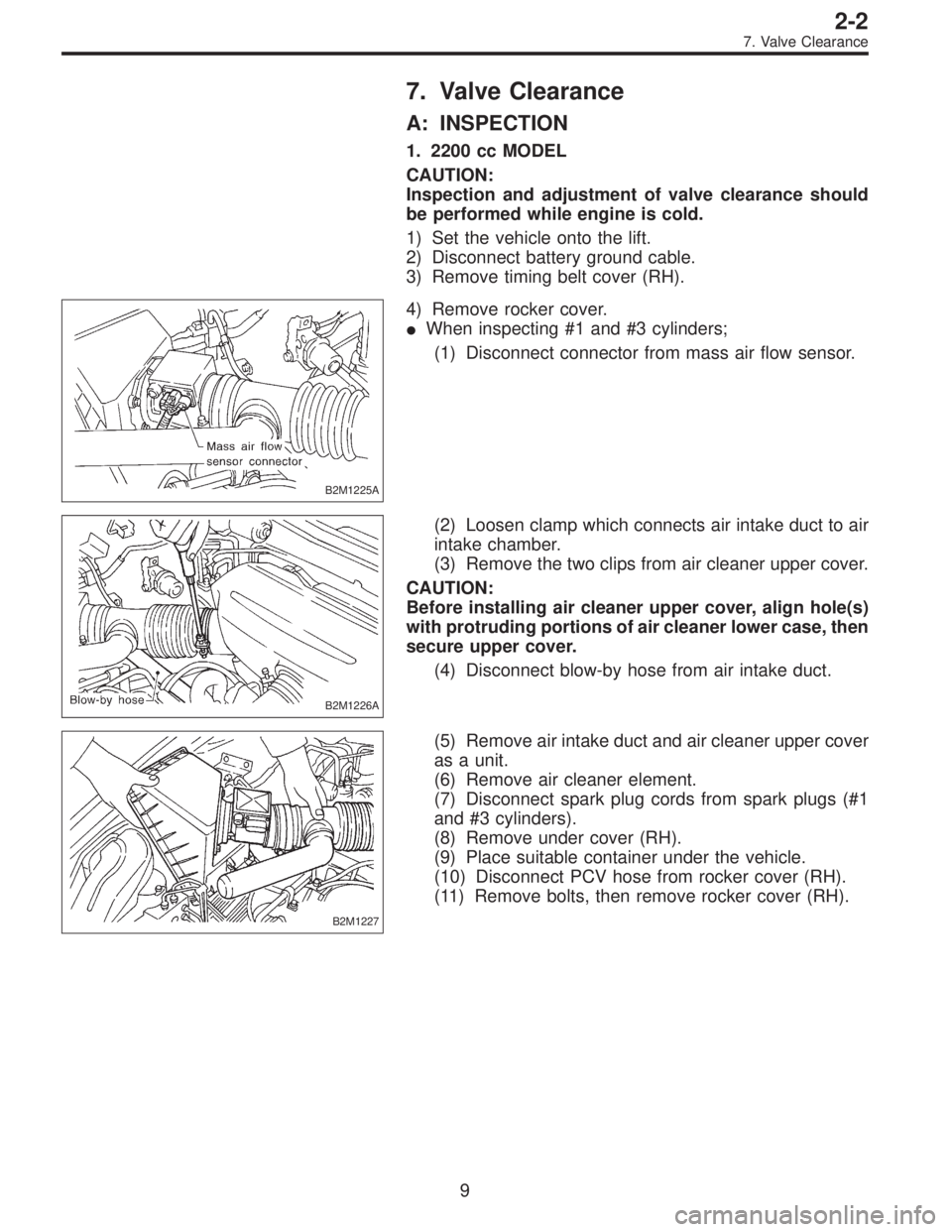
B2M1225A
4) Remove rocker cover.
�When inspecting #1 and #3 cylinders;
(1) Disconnect connector from mass air flow sensor.
B2M1226A
(2) Loosen clamp which connects air intake duct to air
intake chamber.
(3) Remove the two clips from air cleaner upper cover.
CAUTION:
Before installing air cleaner upper cover, align hole(s)
with protruding portions of air cleaner lower case, then
secure upper cover.
(4) Disconnect blow-by hose from air intake duct.
B2M1227
(5) Remove air intake duct and air cleaner upper cover
as a unit.
(6) Remove air cleaner element.
(7) Disconnect spark plug cords from spark plugs (#1
and #3 cylinders).
(8) Remove under cover (RH).
(9) Place suitable container under the vehicle.
(10) Disconnect PCV hose from rocker cover (RH).
(11) Remove bolts, then remove rocker cover (RH).
9
2-2
7. Valve Clearance
Page 256 of 3342
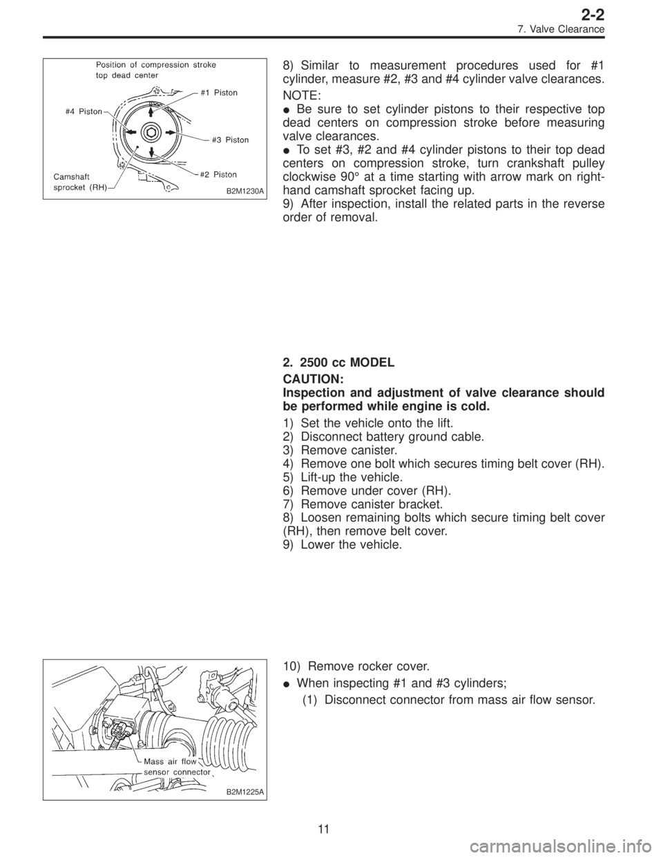
B2M1230A
8) Similar to measurement procedures used for #1
cylinder, measure #2, #3 and #4 cylinder valve clearances.
NOTE:
�Be sure to set cylinder pistons to their respective top
dead centers on compression stroke before measuring
valve clearances.
�To set #3, #2 and #4 cylinder pistons to their top dead
centers on compression stroke, turn crankshaft pulley
clockwise 90°at a time starting with arrow mark on right-
hand camshaft sprocket facing up.
9) After inspection, install the related parts in the reverse
order of removal.
2. 2500 cc MODEL
CAUTION:
Inspection and adjustment of valve clearance should
be performed while engine is cold.
1) Set the vehicle onto the lift.
2) Disconnect battery ground cable.
3) Remove canister.
4) Remove one bolt which secures timing belt cover (RH).
5) Lift-up the vehicle.
6) Remove under cover (RH).
7) Remove canister bracket.
8) Loosen remaining bolts which secure timing belt cover
(RH), then remove belt cover.
9) Lower the vehicle.
B2M1225A
10) Remove rocker cover.
�When inspecting #1 and #3 cylinders;
(1) Disconnect connector from mass air flow sensor.
11
2-2
7. Valve Clearance
Page 381 of 3342
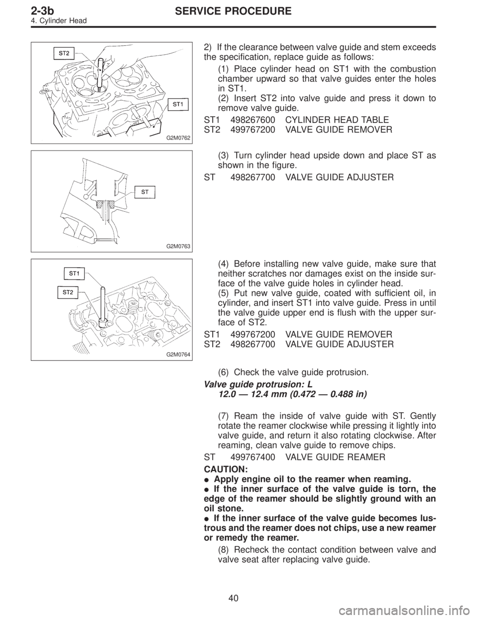
G2M0762
2) If the clearance between valve guide and stem exceeds
the specification, replace guide as follows:
(1) Place cylinder head on ST1 with the combustion
chamber upward so that valve guides enter the holes
in ST1.
(2) Insert ST2 into valve guide and press it down to
remove valve guide.
ST1 498267600 CYLINDER HEAD TABLE
ST2 499767200 VALVE GUIDE REMOVER
G2M0763
(3) Turn cylinder head upside down and place ST as
shown in the figure.
ST 498267700 VALVE GUIDE ADJUSTER
G2M0764
(4) Before installing new valve guide, make sure that
neither scratches nor damages exist on the inside sur-
face of the valve guide holes in cylinder head.
(5) Put new valve guide, coated with sufficient oil, in
cylinder, and insert ST1 into valve guide. Press in until
the valve guide upper end is flush with the upper sur-
face of ST2.
ST1 499767200 VALVE GUIDE REMOVER
ST2 498267700 VALVE GUIDE ADJUSTER
(6) Check the valve guide protrusion.
Valve guide protrusion: L
12.0—12.4 mm (0.472—0.488 in)
(7) Ream the inside of valve guide with ST. Gently
rotate the reamer clockwise while pressing it lightly into
valve guide, and return it also rotating clockwise. After
reaming, clean valve guide to remove chips.
ST 499767400 VALVE GUIDE REAMER
CAUTION:
�Apply engine oil to the reamer when reaming.
�If the inner surface of the valve guide is torn, the
edge of the reamer should be slightly ground with an
oil stone.
�If the inner surface of the valve guide becomes lus-
trous and the reamer does not chips, use a new reamer
or remedy the reamer.
(8) Recheck the contact condition between valve and
valve seat after replacing valve guide.
40
2-3bSERVICE PROCEDURE
4. Cylinder Head
Page 1098 of 3342
G4M0497
4) Connect stabilizer link to transverse link, and tempo-
rarily tighten bolts.
CAUTION:
Discard loosened self-locking nut and replace with a
new one.
5) Tighten the following points in the order shown below
when wheels are in full contact with the ground and vehicle
is at curb weight condition.
(1) Transverse link and stabilizer link
Tightening torque:
29±5 N⋅m (3.0±0.5 kg-m, 21.7±3.6 ft-lb)
(2) Transverse link and crossmember
Tightening torque:
98±15 N⋅m (10.0±1.5 kg-m, 72±11 ft-lb)
G4M0928
(3) Transverse link rear bushing and body
Tightening torque:
245±49 N⋅m (25±5 kg-m, 181±36 ft-lb)
NOTE:
�Move rear bushing back and forth until transverse link-
to-rear bushing clearance is established (as indicated in
figure.) before tightening.
�Check wheel alignment and adjust if necessary.
19
4-1SERVICE PROCEDURE
2. Front Transverse Link
Page 1484 of 3342
11. Compressor
Compressor is a swash plate type. When trouble occurs,
replace compressor as a single unit.
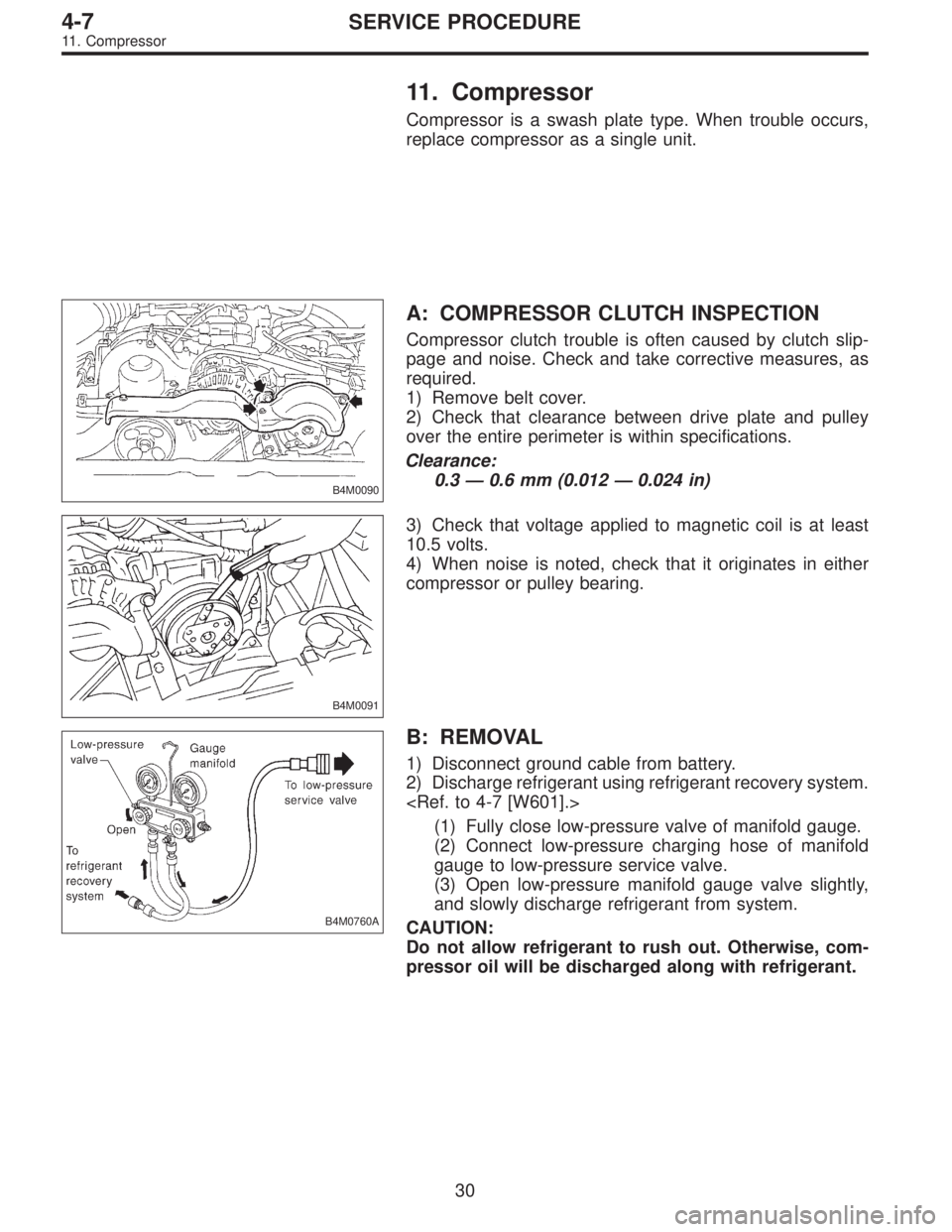
B4M0090
A: COMPRESSOR CLUTCH INSPECTION
Compressor clutch trouble is often caused by clutch slip-
page and noise. Check and take corrective measures, as
required.
1) Remove belt cover.
2) Check that clearance between drive plate and pulley
over the entire perimeter is within specifications.
Clearance:
0.3 — 0.6 mm (0.012 — 0.024 in)
B4M0091
3) Check that voltage applied to magnetic coil is at least
10.5 volts.
4) When noise is noted, check that it originates in either
compressor or pulley bearing.
B4M0760A
B: REMOVAL
1) Disconnect ground cable from battery.
2) Discharge refrigerant using refrigerant recovery system.
(1) Fully close low-pressure valve of manifold gauge.
(2) Connect low-pressure charging hose of manifold
gauge to low-pressure service valve.
(3) Open low-pressure manifold gauge valve slightly,
and slowly discharge refrigerant from system.
CAUTION:
Do not allow refrigerant to rush out. Otherwise, com-
pressor oil will be discharged along with refrigerant.
30
4-7SERVICE PROCEDURE
11. Compressor
Page 1583 of 3342
1. Sunroof
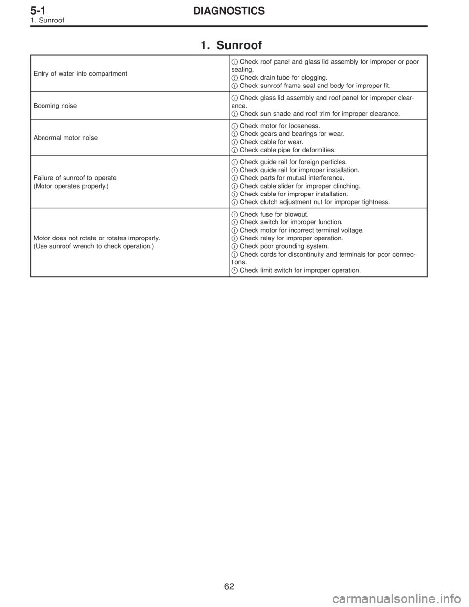
Entry of water into compartment�
1Check roof panel and glass lid assembly for improper or poor
sealing.
�
2Check drain tube for clogging.
�
3Check sunroof frame seal and body for improper fit.
Booming noise�
1Check glass lid assembly and roof panel for improper clear-
ance.
�
2Check sun shade and roof trim for improper clearance.
Abnormal motor noise�
1Check motor for looseness.
�
2Check gears and bearings for wear.
�
3Check cable for wear.
�
4Check cable pipe for deformities.
Failure of sunroof to operate
(Motor operates properly.)�
1Check guide rail for foreign particles.
�
2Check guide rail for improper installation.
�
3Check parts for mutual interference.
�
4Check cable slider for improper clinching.
�
5Check cable for improper installation.
�
6Check clutch adjustment nut for improper tightness.
Motor does not rotate or rotates improperly.
(Use sunroof wrench to check operation.)�
1Check fuse for blowout.
�
2Check switch for improper function.
�
3Check motor for incorrect terminal voltage.
�
4Check relay for improper operation.
�
5Check poor grounding system.
�
6Check cords for discontinuity and terminals for poor connec-
tions.
�
7Check limit switch for improper operation.
62
5-1DIAGNOSTICS
1. Sunroof
Page 1929 of 3342
14) In AT vehicles, do not continue the stall for more than
five seconds at a time (from closed throttle, fully open
throttle to stall engine speed).
15) On ABS or ABS/TCS vehicle, when performing driving
test in jacked-up or lifted-up position, sometimes the warn-
ing light may be lit, but this is not a malfunction of the sys-
tem. The reason for this is the speed difference between
the front and rear wheels. After diagnosis of engine control
system, perform the ABS or ABS/TCS memory clearance
procedure of self-diagnosis system.
[T9K0], or 4-4c [T6D2] or [T9J0], or 4-4d [T6D2] or [T9J0].>
C: PRE-INSPECTION
Before performing diagnostics, check the following items
which might affect engine problems:
1. POWER SUPPLY
1) Measure battery voltage and specific gravity of electro-
lyte.
Standard voltage: 12 V
Specific gravity: Above 1.260
2) Check the condition of the main and other fuses, and
harnesses and connectors. Also check for proper ground-
ing.
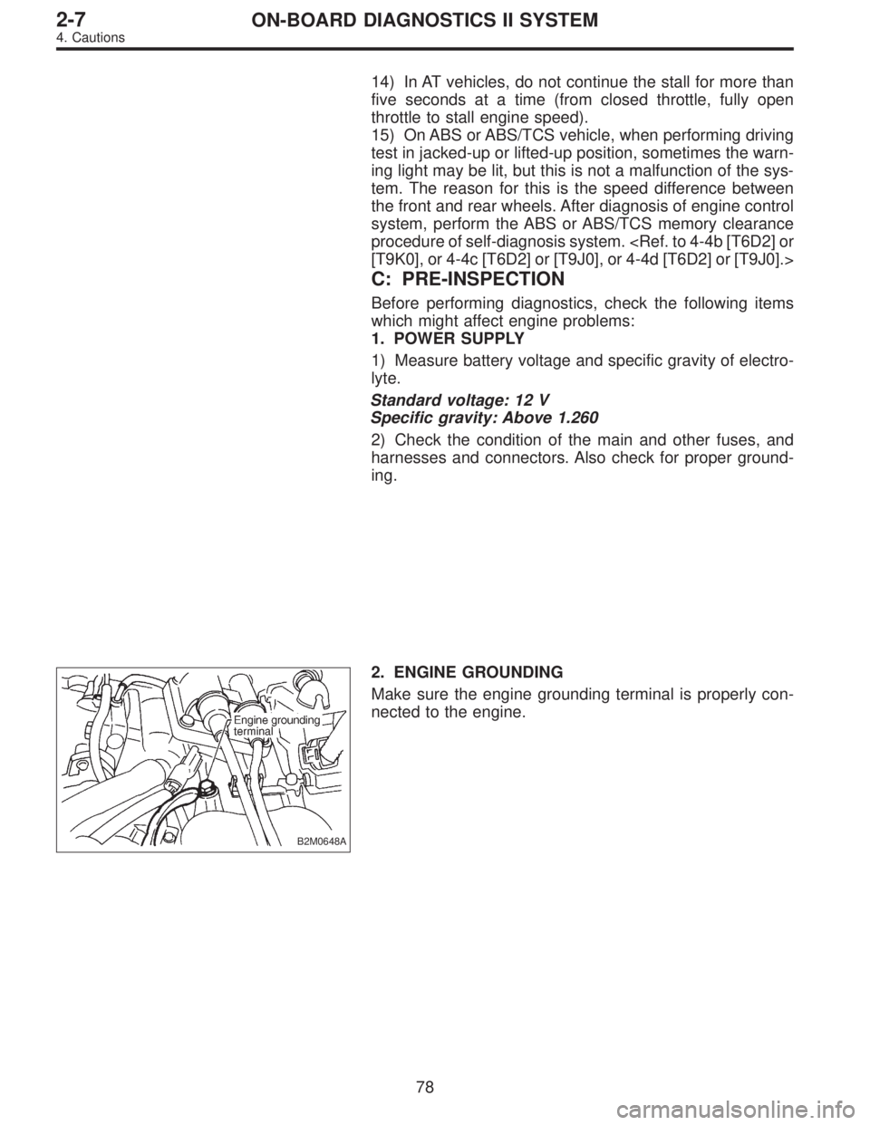
B2M0648A
2. ENGINE GROUNDING
Make sure the engine grounding terminal is properly con-
nected to the engine.
78
2-7ON-BOARD DIAGNOSTICS II SYSTEM
4. Cautions