Page 220 of 3342
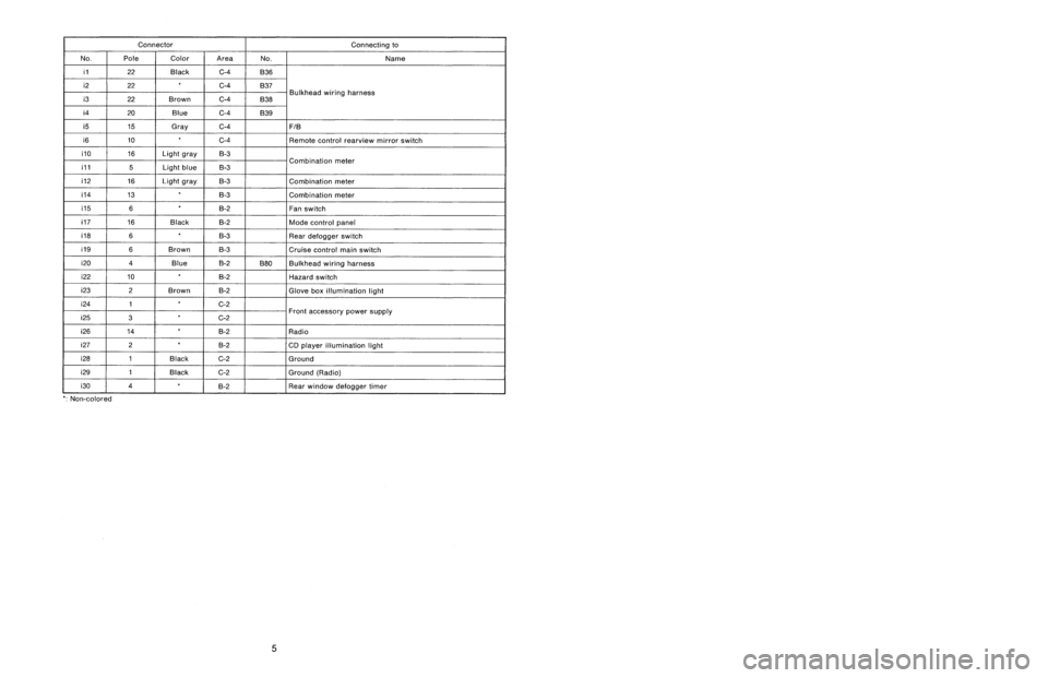
Connector
Connecting
to
No
.
Pole
Color
Area
No
.
Name
i1
22
Black
C-4
B36
i2
22
G4
B37
i3
22
Brown
C-4
B38
Bulkhead
wiring
harness
i4
20
Blue
C-4
B39
i5
15
Gray
C-4F!B
i6
10
C-4
Remote
control
rearview
mirror
switch
i10
16
Light
gray
B-3
i11
5
Light
blueB-3
Combination
meter
i12
16
Light
gray
B-3
Combination
meter
04
13
B-3
Combination
meter
05
6B-2
Fan
switch
07
16
Black
B-2
Mode
control
panel
08
6B-3
Rear
defogger
switch
09
6
Brown
B-3Cruise
control
main
switch
i20
4
Blue
B-2
B80
Bulkhead
wiring
harness
i22
10
B-2
Hazard
switch
i23
2
Brown
B-2
Glove
box
illumination
light
i24
1
G2
i25
3C-2Front
accessory
power
supply
i26
14
B-2
Radio
i27
2B-2
CD
player
illumination
light
i28
1
Black
C-2
Ground
i29
1
Black
C-2
Ground
(Radio)
i30
4B-2
Rear
window
defogger
timer
'
:
Non-colored
5
.
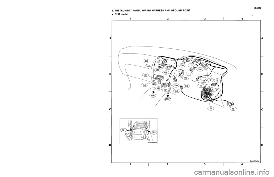
INSTRUMENT
PANEL
WIRING
HARNESS
AND
GROUND
POINT
9
RHD
model
1
23
AI
B
C
DI
1
2
3
5
Page 221 of 3342
Connector
Connecting
to
ole
Color
Area
No
.
Name
22
Black
C-4
B36
22
C-4
B37
lkh
ii
h
?2
Brown
C-4
B38
ead
w
r
ng
arness
Bu
20
Blue
C-4
B39
15
Gray
C-4
FIB
10
C-4
Remote
control
rearview
mirrorswitch
16
Light
gray
B-3
ii
5
Light
blue
B-3
Comb
nat
on
meter
16
Light
gray
B-3
Combination
meter
13
B-3
Combination
meter
6
B-2
Fan
switch
16
Black
B-2
Mode
control
panel
6
B-3
Rear
defogger
switch
6
Brown
B-3
Cruise
control
main
switch
4
Blue
B-2
B80
Bulkhead
wiring
harness
10
B-2
Hazard
switch
2
Brown
B-2
Glove
box
illumination
light
1
G2
F3
G2
ront
accessory
power
supply
14
8-2
Radio
2B-2
CD
player
illumination
light
1
Black
C-2
Ground
1
Black
G2
Ground
(Radio)
4
B-2
Rear
window
defogger
timer
5
.
INSTRUMENT
PANEL
WIRING
HARNESS
AND
GROUND
POINT
e
RHD
model
1
I
2
I
3
A
B
C
D
1
2
3
4
4
[D805]
B6M0849A
A
B
C
C
5
Page 222 of 3342
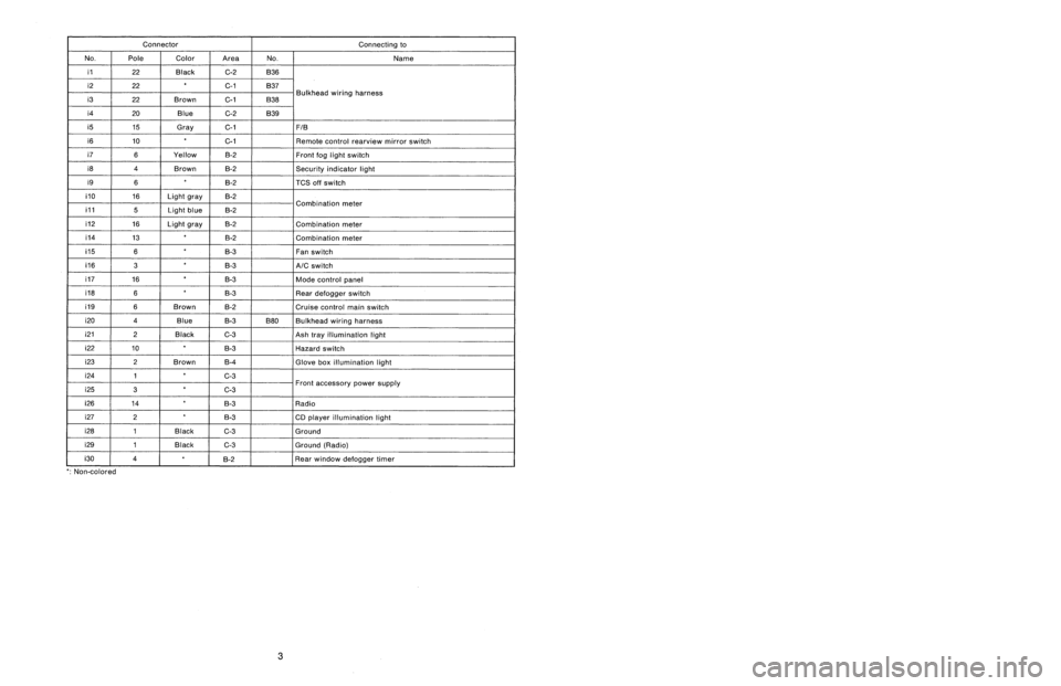
Connector
Connecting
to
No
.
Pole
Color
Area
No
.
Name
i1
22
Black
C-2
B36
i2
22C-1
B37
i3
22
Brown
C-1
B38
Bulkhead
wiring
harness
i4
20
Blue
C-2
B39
i5
15
Gray
C-1F1B
i6
10
C-1
Remote
control
rearview
mirrorswitch
i7
6
Yellow
B-2Front
fog
light
switch
i8
4
Brown
B-2Security
indicator
light
i9
6B-2
TCS
off
switch
i10
16
Light
gray
B-2
i11
5
Light
blueB-2
Combination
meter
i12
16
Light
gray
B-2
Combination
meter
i14
13
B-2
Combination
meter
05
6
B-3
Fan
switch
06
3
B-3
A/C
switch
07
16
B-3
Mode
control
panel
08
6B-3
Rear
defogger
switch
09
6
Brown
B-2
Cruise
control
main
switch
i20
4
Blue
B-3
B80
Bulkhead
wiring
harness
i212
Black
C-3
Ash
tray
illumination
light
i22
10
B-3
Hazard
switch
i23
2
Brown
B-4
Glove
box
illumination
light
i24
1
C-3
i25
3
C-3Front
accessory
power
supply
i26
14
B-3
Radio
i27
2B-3
CD
player
illumination
light
i28
1
Black
C-3
Ground
i29
1
Black
G3
Ground
(Radio)
i30
4
~
°
g-2
Rear
window
defogger
timer
'
:
Non-colored
8
.
Electrical
Wiring
Harness
and
Ground
Point
5
.
INSTRUMENT
PANEL
WIRING
HARNESS
AND
GROUND
POINT
9
LHD
model
1
23
A
B
CII
C
DI
3
1
23
Page 223 of 3342
Connector
Connecting
to
ole
Color
Area
No
.
Name
?2
Black
G2
B36
?2
C-1
B37
lkh
ii
h
?2
Brown
C-1
B38ead
w
r
ng
arness
Bu
?0
Blue
G-2
B39
15
Gray
C-1FIB
10
C-1
Remote
control
rearview
mirrorswitch
6
Yellow
B-2
Front
fog
light
switch
4
Brown
B-2Security
indicator
light
6B-2
TCS
off
switch
16
Light
gray
B-2
ii
5
Light
blueB-2
Comb
nat
on
meter
16
Light
gray
B-2
Combination
meter
13
~
B-2
Combination
meter
6B-3
Fan
switch
3B-3
A/C
switch
16
B-3
Mode
control
panel
6
B-3
Rear
defogger
switch
6
Brown
8-2Cruise
control
main
switch
4
Blue
B-3B80
Bulkhead
wiring
harness
?
Black
C-3
Ash
trayillumination
light
0
B-3
Hazard
switch
?
Brown
B-4
Glove
box
illumination
light
1
C-3
3
C-3Front
accessory
power
supply
4B-3
Radio
2
B-3
CD
player
illumination
light
I
Black
C-3
Ground
I
Black
C-3
Ground
(Radio)
B-2
~
~
Rear
window
defogger
timer
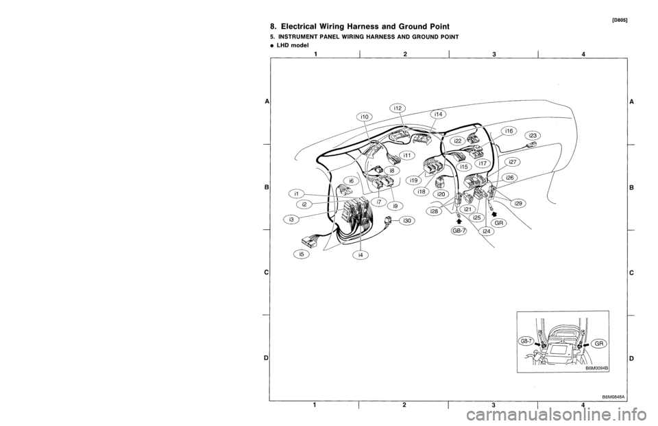
3
8
.
Electrical
Wiring
Harness
andGround
Point
5
.
INSTRUMENT
PANEL
WIRING
HARNESS
AND
GROUND
POINT
e
LHD
model
[D805]
1
I
2
I
3
A
B
C
1
2
3
4
4
B6M0848A
A
B
C
Page 1587 of 3342
3. Front Door Glass
B5M0054A
�1Glass
�
2Regulator and motor ASSY
�
3Regulator handle (Except power window)
�
4Retainer spring
�
5Regulator ASSY
Tightening torque: N⋅m (kg-m, ft-lb)
T: 7.4±2.0 (0.75±0.2, 5.4±1.4)
5
5-2COMPONENT PARTS
3. Front Door Glass
Page 1588 of 3342
4. Rear Door Glass
B5M0055A
�1Glass
�
2Regulator and motor ASSY
�
3Regulator handle (Except power window)
�
4Retainer spring
�
5Regulator ASSY
Tightening torque: N⋅m (kg-m, ft-lb)
T: 7.4±2.0 (0.75±0.2, 5.4±1.4)
6
5-2COMPONENT PARTS
4. Rear Door Glass
Page 1595 of 3342
G5M0486
2. Door
A: REMOVAL AND INSTALLATION
1. DOOR ASSY
1) Remove lower trim and disconnect connectors from
body harness.
2) Place a cloth or a wood block under door to prevent
damage, and support it with a jack.
3) Remove checker pin by driving it upward. Be careful not
to damage door and body.
G5M0385
4) Remove bolts (M8) securing upper and lower hinges to
door, and remove door from hinges.
Tightening torque:
25±3 N⋅m (2.5±0.3 kg-m, 18.1±2.2 ft-lb)
5) Remove hinges by loosening hinges mounting bolt (M8)
off of body.
Tightening torque:
29±5 N⋅m (3.0±0.5 kg-m, 21.7±3.6 ft-lb)
CAUTION:
Work carefully to avoid damaging door.
6) Installation is in the reverse order of removal.
NOTE:
Apply grease to moving parts of door hinges.
B5M0329A
2. TRIM PANEL
1) Press retainer spring�
1with a thin flat bladed screw-
driver and then remove regulator handle�
2. (models with-
out power window)
B5M0061A
2) Remove gusset cover�1and three screws.
13
5-2SERVICE PROCEDURE
2. Door
Page 1596 of 3342
G5M0390
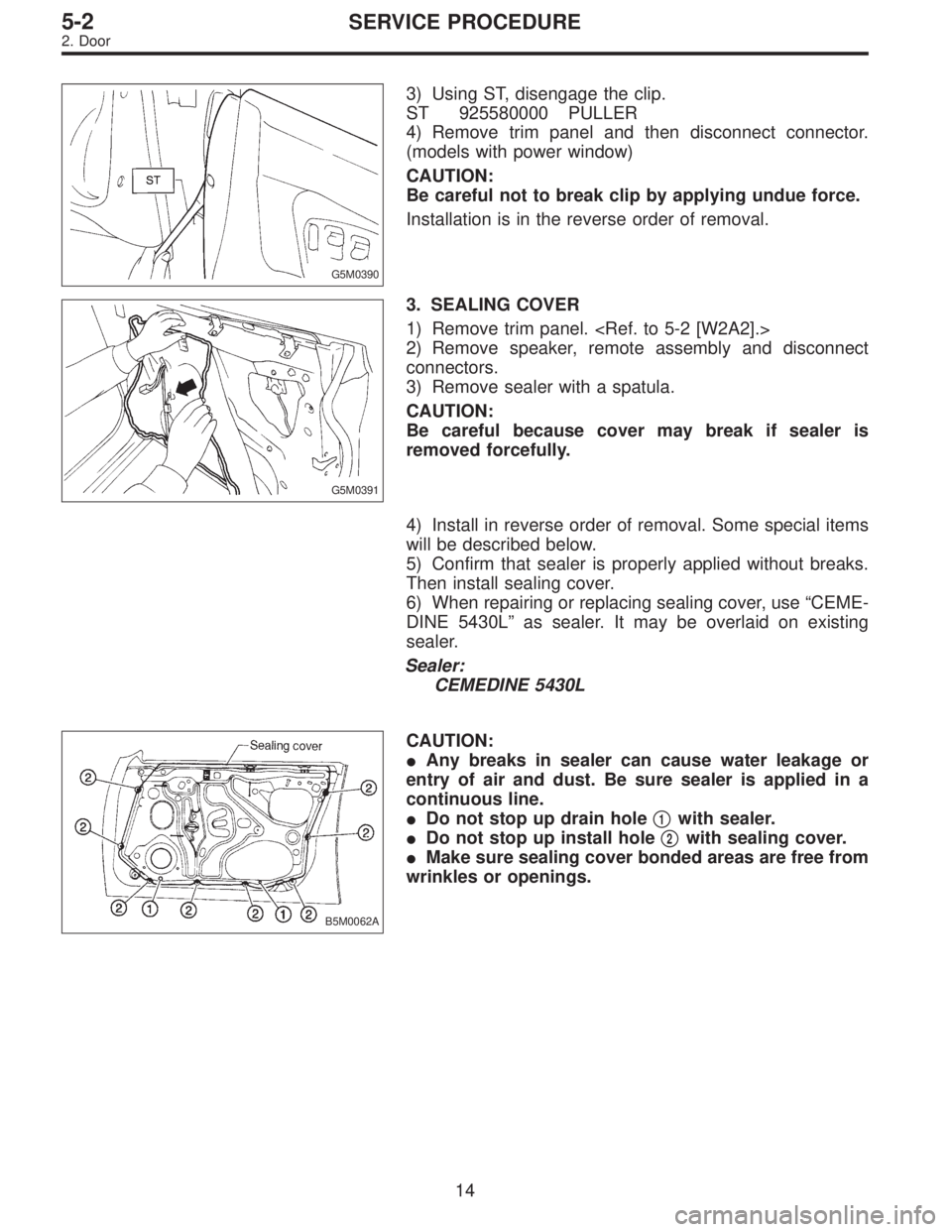
3) Using ST, disengage the clip.
ST 925580000 PULLER
4) Remove trim panel and then disconnect connector.
(models with power window)
CAUTION:
Be careful not to break clip by applying undue force.
Installation is in the reverse order of removal.
G5M0391
3. SEALING COVER
1) Remove trim panel.
2) Remove speaker, remote assembly and disconnect
connectors.
3) Remove sealer with a spatula.
CAUTION:
Be careful because cover may break if sealer is
removed forcefully.
4) Install in reverse order of removal. Some special items
will be described below.
5) Confirm that sealer is properly applied without breaks.
Then install sealing cover.
6) When repairing or replacing sealing cover, use “CEME-
DINE 5430L” as sealer. It may be overlaid on existing
sealer.
Sealer:
CEMEDINE 5430L
B5M0062A
CAUTION:
�Any breaks in sealer can cause water leakage or
entry of air and dust. Be sure sealer is applied in a
continuous line.
�Do not stop up drain hole�
1with sealer.
�Do not stop up install hole�
2with sealing cover.
�Make sure sealing cover bonded areas are free from
wrinkles or openings.
14
5-2SERVICE PROCEDURE
2. Door