Page 1156 of 3342
 Remove front drive shaft assembly. If it is hard to
remove, use ST1 and ST2.
ST1 926470000 AXLE SHAFT PULLER
ST2 927140000 PLATE
CAUTION:
�Be careful not to damage oil seal lip when removin")
G4M0216
8) Remove front drive shaft assembly. If it is hard to
remove, use ST1 and ST2.
ST1 926470000 AXLE SHAFT PULLER
ST2 927140000 PLATE
CAUTION:
�Be careful not to damage oil seal lip when removing
front drive shaft.
�When front drive shaft is to be replaced, also replace
inner oil seal.
2. REAR DRIVE SHAFT
1) Disconnect ground cable from battery.
2) Lift-up vehicle, and remove rear wheel cap and wheels.
CAUTION:
Be sure to loosen and retighten axle nut after remov-
ing wheel from vehicle. Failure to follow this rule may
damage wheel bearings.
3) Unlock axle nut.
4) Loosen axle nut using a socket wrench.
CAUTION:
Do not remove axle nut.
5) Remove A.B.S. sensor clamps and parking brake cable
bracket.
6) Remove bolts which secure lateral link assembly to rear
housing.
CAUTION:
Discard old self-locking nut. Replace with a new one.
7) Remove bolts which secure trailing link assembly to
rear housing.
CAUTION:
Discard old self-locking nut. Replace with a new one.
8) Remove crossmember reinforcement lower from cross-
member (4 door model only).
G4M0994
9) Remove DOJ from rear differential using ST.
ST 28099PA100 DRIVE SHAFT REMOVER
CAUTION:
Do not remove circlip attached to inside of differential.
29
4-2SERVICE PROCEDURE
4. Front and Rear Drive Shafts
Page 1172 of 3342
 Align DOJ and differential splines.
7) Push housing to insert DOJ into differential.
NOTE:
Make sure DOJ is inserted properly.
8) Connect crossmember reinforcement lower to cross-
member (4")
G3M0050
6) Align DOJ and differential splines.
7) Push housing to insert DOJ into differential.
NOTE:
Make sure DOJ is inserted properly.
8) Connect crossmember reinforcement lower to cross-
member (4 door model only).
9) Connect rear housing assembly to trailing link
assembly, and tighten self-locking nut.
Tightening torque:
113±15 N⋅m (11.5±1.5 kg-m, 83±11 ft-lb)
10) Connect rear housing assembly to lateral link
assembly, and tighten self-locking nut.
Tightening torque:
137±20 N⋅m (14±2 kg-m, 101±14 ft-lb)
11) Install stabilizer bracket.
12) While depressing brake pedal, tighten axle nut using
a socket wrench.
Tightening torque:
186±20 N⋅m (19±2 kg-m, 137±14 ft-lb)
CAUTION:
�Use a new axle nut.
�Always tighten axle nut before installing wheel on
vehicle. If wheel is installed and comes in contact with
ground when axle nut is loose, wheel bearings may be
damaged.
�Be sure to tighten axle nut to specified torque. Do
not overtighten it as this may damage wheel bearing.
13) After tightening axle nut, lock it securely.
45
4-2SERVICE PROCEDURE
4. Front and Rear Drive Shafts
Page 1175 of 3342
B4M0549A
2) Using ST, install DOJ into differential.
ST 28099PA090 SIDE OIL SEAL PROTECTOR
B4M0550A
3) Insert DOJ spline end into bore of side oil seal, and
remove ST.
CAUTION:
Do not allow DOJ splines to damage side oil seal.
ST 28099PA090 SIDE OIL SEAL PROTECTOR
G3M0050
4) Align DOJ and differential splines.
5) Push housing to insert DOJ into differential.
NOTE:
Make sure DOJ is inserted properly.
CAUTION:
Discard old self-locking nut. Replace with a new one.
6) Connect rear housing assembly to trailing link
assembly, and tighten self-locking nut.
7) Connect rear housing assembly to lateral link assembly,
and tighten self-locking nut.
8) Connect stabilizer link to lateral link.
9) Install crossmember reinforcement lower to crossmem-
ber (4 door model only).
10) Install A.B.S. sensor clamps and parking brake cable
bracket.
48
4-2SERVICE PROCEDURE
6. Replacement of Rear DOJ and BJ Boots
Page 1454 of 3342
B4M0063
6. Mode Door Motor
A: REMOVAL
1) Remove instrument panel.
2) Remove mode door motor.
B4M0064A
B: INSPECTION
1) When approx. 12 V is applied to the mode door motor
terminals, mode door motor operates as follows:
Terminal No.
Mode door motor
21
Polarity of power supply
terminalsMode door motor
operationDirection of linkage
rotation
� + VENT,DEF Clockwise
+� DEF,VENT Counterclockwise
2) Check mode door motor position switch.
When the mode door motor is moved to each mode posi-
tion by using the mode selector switch, check if continuity
exists between each terminal as follows:
Mode selector switch
positionsTerminal No.
VENT 8 or 7
9 (GND) BI-LEV 6 or 7
HEAT 5or6
DEF/HEAT 4 or 5
DEF 3or4
C: INSTALLATION
Installation is in the reverse order of removal.
13
4-6SERVICE PROCEDURE
6. Mode Door Motor
Page 1589 of 3342
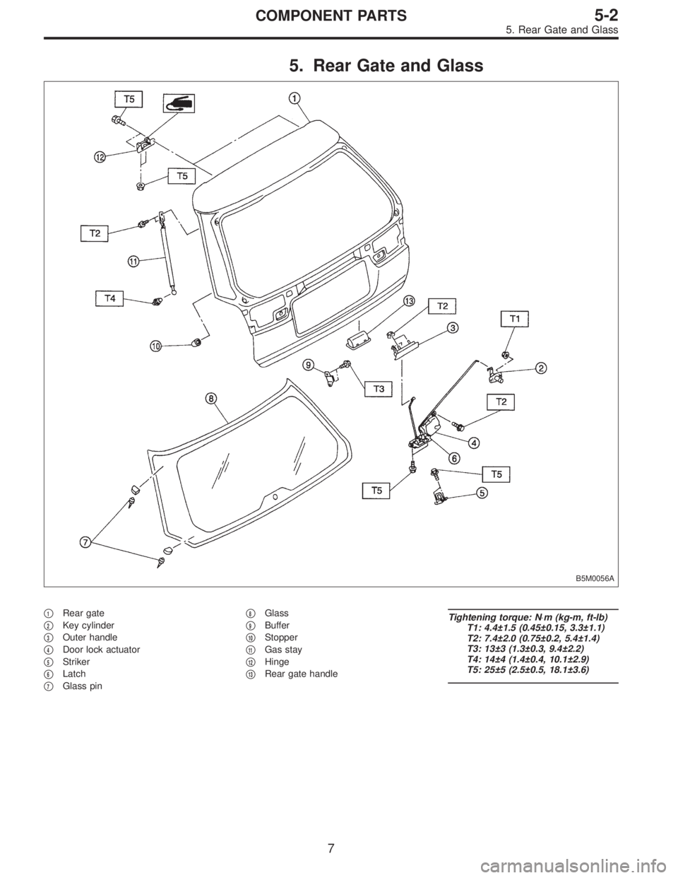
5. Rear Gate and Glass
B5M0056A
�1Rear gate
�
2Key cylinder
�
3Outer handle
�
4Door lock actuator
�
5Striker
�
6Latch
�
7Glass pin�
8Glass
�
9Buffer
�
10Stopper
�
11Gas stay
�
12Hinge
�
13Rear gate handle
Tightening torque: N⋅m (kg-m, ft-lb)
T1: 4.4±1.5 (0.45±0.15, 3.3±1.1)
T2: 7.4±2.0 (0.75±0.2, 5.4±1.4)
T3: 13±3 (1.3±0.3, 9.4±2.2)
T4: 14±4 (1.4±0.4, 10.1±2.9)
T5: 25±5 (2.5±0.5, 18.1±3.6)
7
5-2COMPONENT PARTS
5. Rear Gate and Glass
Page 1590 of 3342
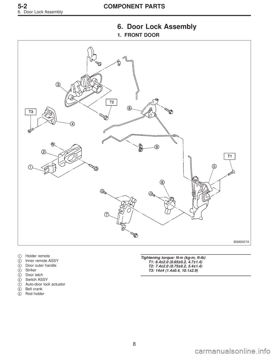
6. Door Lock Assembly
1. FRONT DOOR
B5M0057A
�1Holder remote
�
2Inner remote ASSY
�
3Door outer handle
�
4Striker
�
5Door latch
�
6Switch ASSY
�
7Auto-door lock actuator
�
8Bell crank
�
9Rod holder
Tightening torque: N⋅m (kg-m, ft-lb)
T1: 6.4±2.0 (0.65±0.2, 4.7±1.4)
T2: 7.4±2.0 (0.75±0.2, 5.4±1.4)
T3: 14±4 (1.4±0.4, 10.1±2.9)
8
5-2COMPONENT PARTS
6. Door Lock Assembly
Page 1591 of 3342
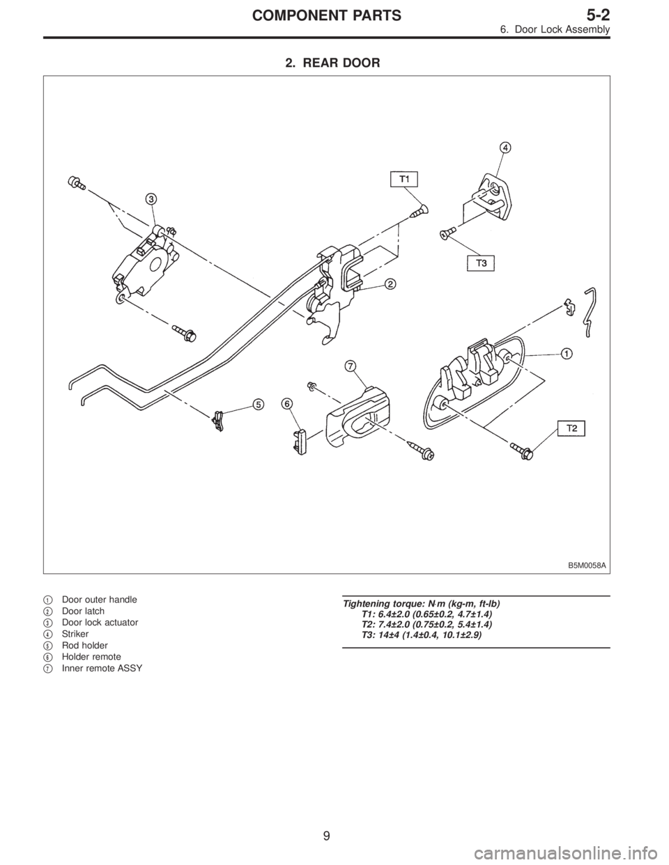
2. REAR DOOR
B5M0058A
�1Door outer handle
�
2Door latch
�
3Door lock actuator
�
4Striker
�
5Rod holder
�
6Holder remote
�
7Inner remote ASSY
Tightening torque: N⋅m (kg-m, ft-lb)
T1: 6.4±2.0 (0.65±0.2, 4.7±1.4)
T2: 7.4±2.0 (0.75±0.2, 5.4±1.4)
T3: 14±4 (1.4±0.4, 10.1±2.9)
9
5-2COMPONENT PARTS
6. Door Lock Assembly
Page 1594 of 3342

1. Procedure Chart for Removing and
Installing Door and Related Parts
NOTE:
This flow chart shows the main procedures for removing
and installing the door and its related parts. For details,
refer to the text.
DoorDoor lock systemDoor regulator
�
Door glass
�
Remove door trim parts, etc.
�
REMOVALRemove front and rear upper stoppers
and stabilizer (inner).
�
Remove door.Disconnect joints
between latch, outer
handle, key lock and
remote assembly.Separate door glass from regulator.
Remove guide
channel B.Remove door
glass.
Remove door
lock system.Remove
regulator.
Install door.Install door
lock system.Install regulator.
Install guide
channel.Insert door glass.
�
Adjust door alignment.Adjust door
lock system.Mount door glass on regulator.
�
INSTALLATION
AND
ADJUSTMENTAdjust striker.Link latch, outer handle,
key lock and remote
assembly together.Install front and rear upper stoppers
and stabilizer (inner).
�
Adjust glass position.
��
Install door trim parts, etc.
���
Confirm.
�
�
���
��
��
���
��
���
���
�
�
�
12
5-2SERVICE PROCEDURE
1. Procedure Chart for Removing and Installing Door and Related Parts
 Using ST, install DOJ into differential.
ST 28099PA090 SIDE OIL SEAL PROTECTOR
B4M0550A
3) Insert DOJ spline end into bore of side oil seal, and
remove ST.
CAUTION:
Do not allow DOJ spline")
![SUBARU LEGACY 1997 Service Repair Manual B4M0063
6. Mode Door Motor
A: REMOVAL
1) Remove instrument panel. <Ref. to 5-4 [W1A0].>
2) Remove mode door motor.
B4M0064A
B: INSPECTION
1) When approx. 12 V is applied to the mode door motor
termina](/manual-img/17/57434/w960_57434-1453.png "SUBARU LEGACY 1997 Service Repair Manual B4M0063
6. Mode Door Motor
A: REMOVAL
1) Remove instrument panel. <Ref. to 5-4 [W1A0].>
2) Remove mode door motor.
B4M0064A
B: INSPECTION
1) When approx. 12 V is applied to the mode door motor
termina")