Page 435 of 3342
Lower level
3.5�(3.7 US qt, 3.1 Imp qt)
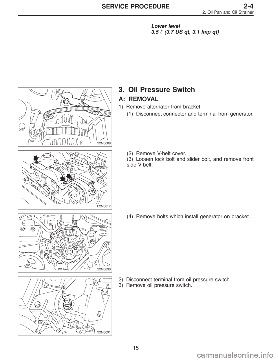
G2M0088
3. Oil Pressure Switch
A: REMOVAL
1) Remove alternator from bracket.
(1) Disconnect connector and terminal from generator.
B2M0017
(2) Remove V-belt cover.
(3) Loosen lock bolt and slider bolt, and remove front
side V-belt.
G2M0090
(4) Remove bolts which install generator on bracket.
G2M0091
2) Disconnect terminal from oil pressure switch.
3) Remove oil pressure switch.
15
2-4SERVICE PROCEDURE
2. Oil Pan and Oil Strainer
Page 436 of 3342
Lower level
3.5�(3.7 US qt, 3.1 Imp qt)
G2M0088
3. Oil Pressure Switch
A: REMOVAL
1) Remove alternator from bracket.
(1) Disconnect connector and terminal from generator.
B2M0017
(2) Remove V-belt cover.
(3) Loosen lock bolt and slider bolt, and remove front
side V-belt.
G2M0090
(4) Remove bolts which install generator on bracket.
G2M0091
2) Disconnect terminal from oil pressure switch.
3) Remove oil pressure switch.
15
2-4SERVICE PROCEDURE
2. Oil Pan and Oil Strainer
Page 600 of 3342
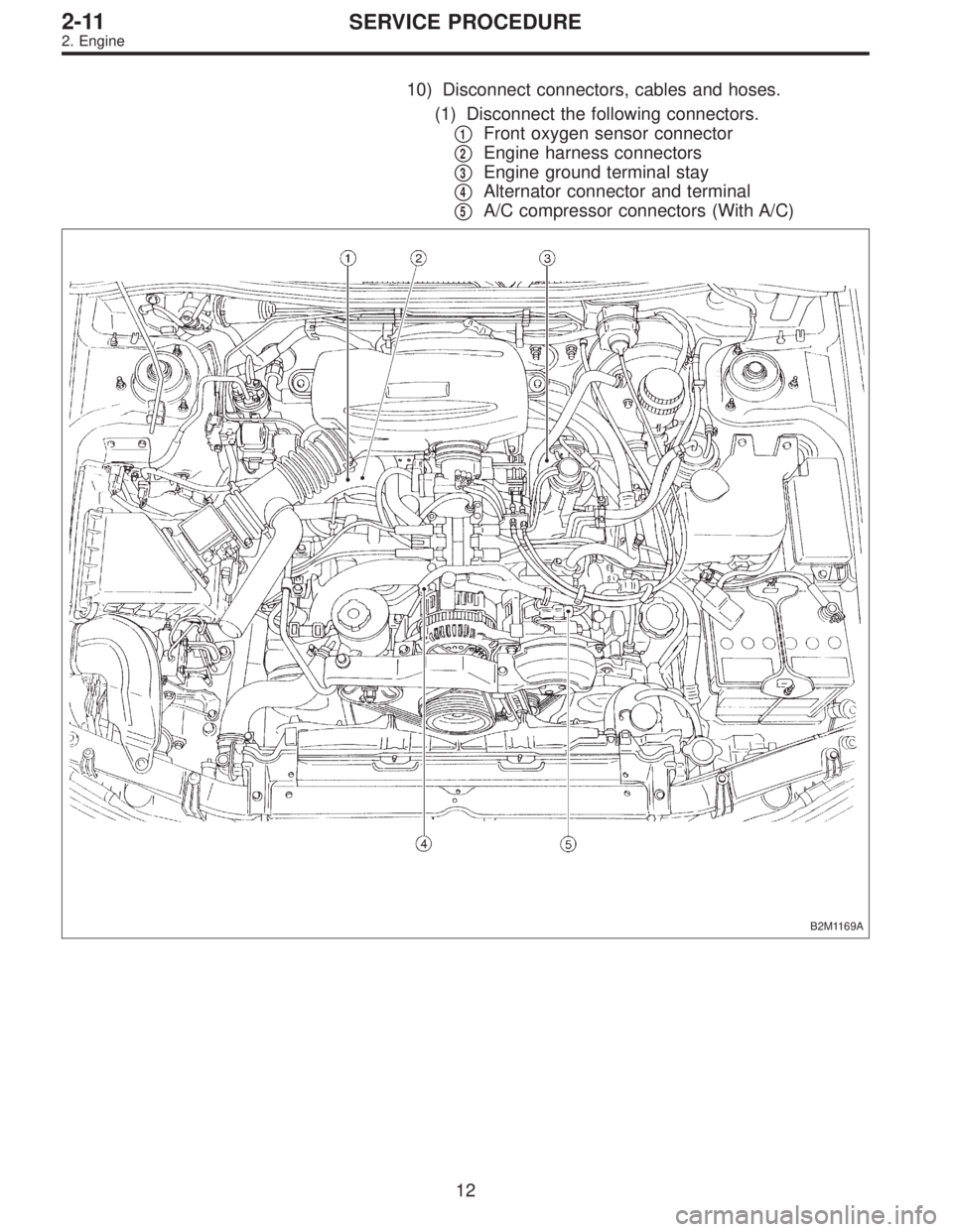
10) Disconnect connectors, cables and hoses.
(1) Disconnect the following connectors.
�
1Front oxygen sensor connector
�
2Engine harness connectors
�
3Engine ground terminal stay
�
4Alternator connector and terminal
�
5A/C compressor connectors (With A/C)
B2M1169A
12
2-11SERVICE PROCEDURE
2. Engine
Page 612 of 3342
 Install front exhaust pipe and center exhaust pipe.
12) Connect hoses, connectors and cables.
(1) Connect the following hoses.
�Fuel delivery hose, return hose and evaporation
hose
�Heater inlet a")
11) Install front exhaust pipe and center exhaust pipe.
12) Connect hoses, connectors and cables.
(1) Connect the following hoses.
�Fuel delivery hose, return hose and evaporation
hose
�Heater inlet and outlet hoses
�Brake booster vacuum hose
(2) Connect the following connectors.
�Engine ground terminal
�Engine harness connectors
�Front oxygen sensor connector
�Rear oxygen sensor connector
�Alternator connector and terminal
�A/C compressor connectors (With A/C)
(3) Connect the following cables.
�Accelerator cable
�Cruise control cables (With cruise control)
�Clutch cable
�Clutch release spring
CAUTION:
After connecting each cable, adjust them.
B2M1168
13) Install air intake system.
(1) Install air cleaner element.
(2) Install air intake duct with air cleaner upper cover.
B2M0030
(3) Connect connector to mass air flow sensor.
G2M0270
14) Install A/C pressure hoses. (With A/C)
CAUTION:
Use new O-rings.
Tightening torque:
25±7 N⋅m (2.5±0.7 kg-m, 18.1±5.1 ft-lb)
24
2-11SERVICE PROCEDURE
2. Engine
Page 1254 of 3342

A: REMOVAL
1) Remove ground cable from battery.
2) Drain the working fluid about 0.35�(0.4 US qt, 0.3 Imp
qt) from oil tank.
3) Remove pulley belt cover bra")
B4M1160
8. Oil Pump (Power Steering System)
A: REMOVAL
1) Remove ground cable from battery.
2) Drain the working fluid about 0.35�(0.4 US qt, 0.3 Imp
qt) from oil tank.
3) Remove pulley belt cover bracket.
B4M1161A
4) Loosen oil pump pulley nut, then remove bolts which
secure alternator.
5) Loosen pulley belt(s).
6) Remove the nut and detach oil pump pulley.
B4M1159A
7) Remove bolt A. Disconnect pipe C from oil pump. Dis-
connect pipe D from oil tank.
CAUTION:
�Do not allow fluid from the hose end to come into
contact with pulley belt.
�To prevent foreign matter from entering the hose
and pipe, cover the open ends of them with a clean
cloth.
�Except when only oil tank needs to be inspected,
detach oil tank and oil pump as a unit. Then separate
one from the other on a work bench to prevent oil from
spilling on any part of the engine.
B4M0560
8) Remove three bolts from the front side of oil pump and
detach the pump.
9) Remove three bolts from the lower side of bracket and
detach the bracket.
CAUTION:
The bracket does not need to be removed unless it is
damaged.
70
4-3SERVICE PROCEDURE
8. Oil Pump (Power Steering System)
Page 1460 of 3342
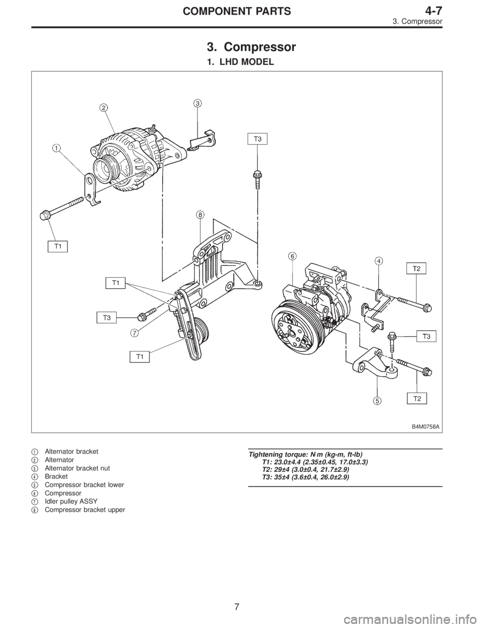
3. Compressor
1. LHD MODEL
B4M0758A
�1Alternator bracket
�
2Alternator
�
3Alternator bracket nut
�
4Bracket
�
5Compressor bracket lower
�
6Compressor
�
7Idler pulley ASSY
�
8Compressor bracket upper
Tightening torque: N⋅m (kg-m, ft-lb)
T1: 23.0±4.4 (2.35±0.45, 17.0±3.3)
T2: 29±4 (3.0±0.4, 21.7±2.9)
T3: 35±4 (3.6±0.4, 26.0±2.9)
7
4-7COMPONENT PARTS
3. Compressor
Page 1461 of 3342
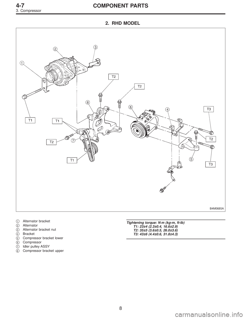
2. RHD MODEL
B4M0685A
�1Alternator bracket
�
2Alternator
�
3Alternator bracket nut
�
4Bracket
�
5Compressor bracket lower
�
6Compressor
�
7Idler pulley ASSY
�
8Compressor bracket upper
Tightening torque: N⋅m (kg-m, ft-lb)
T1: 23±4 (2.3±0.4, 16.6±2.9)
T2: 35±5 (3.6±0.5, 26.0±3.6)
T3: 43±6 (4.4±0.6, 31.8±4.3)
8
4-7COMPONENT PARTS
3. Compressor
Page 1485 of 3342
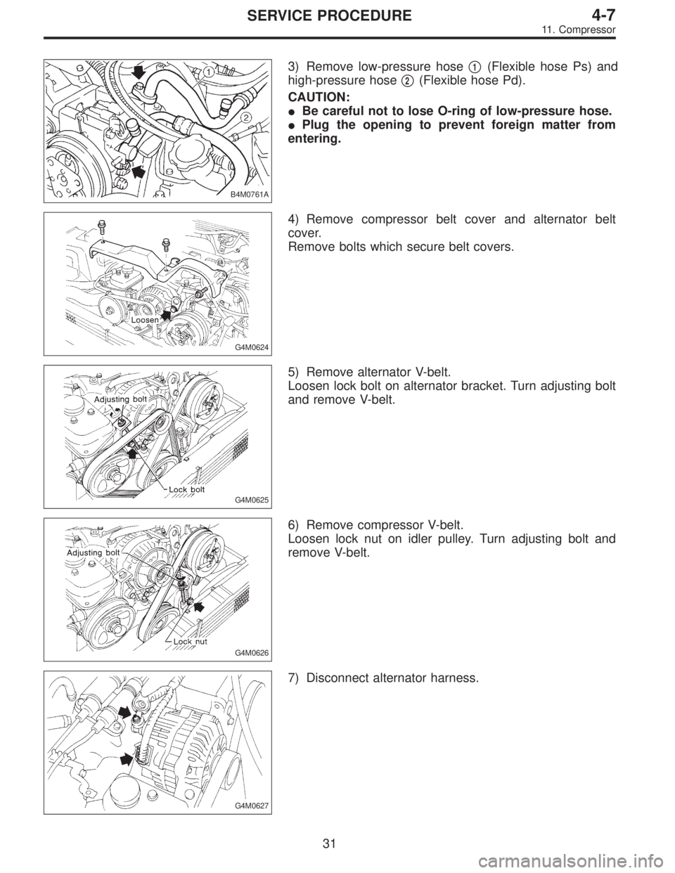
B4M0761A
3) Remove low-pressure hose�1(Flexible hose Ps) and
high-pressure hose�
2(Flexible hose Pd).
CAUTION:
�Be careful not to lose O-ring of low-pressure hose.
�Plug the opening to prevent foreign matter from
entering.
G4M0624
4) Remove compressor belt cover and alternator belt
cover.
Remove bolts which secure belt covers.
G4M0625
5) Remove alternator V-belt.
Loosen lock bolt on alternator bracket. Turn adjusting bolt
and remove V-belt.
G4M0626
6) Remove compressor V-belt.
Loosen lock nut on idler pulley. Turn adjusting bolt and
remove V-belt.
G4M0627
7) Disconnect alternator harness.
31
4-7SERVICE PROCEDURE
11. Compressor