Page 1038 of 3342

G3M0703
E: INSTALLATION
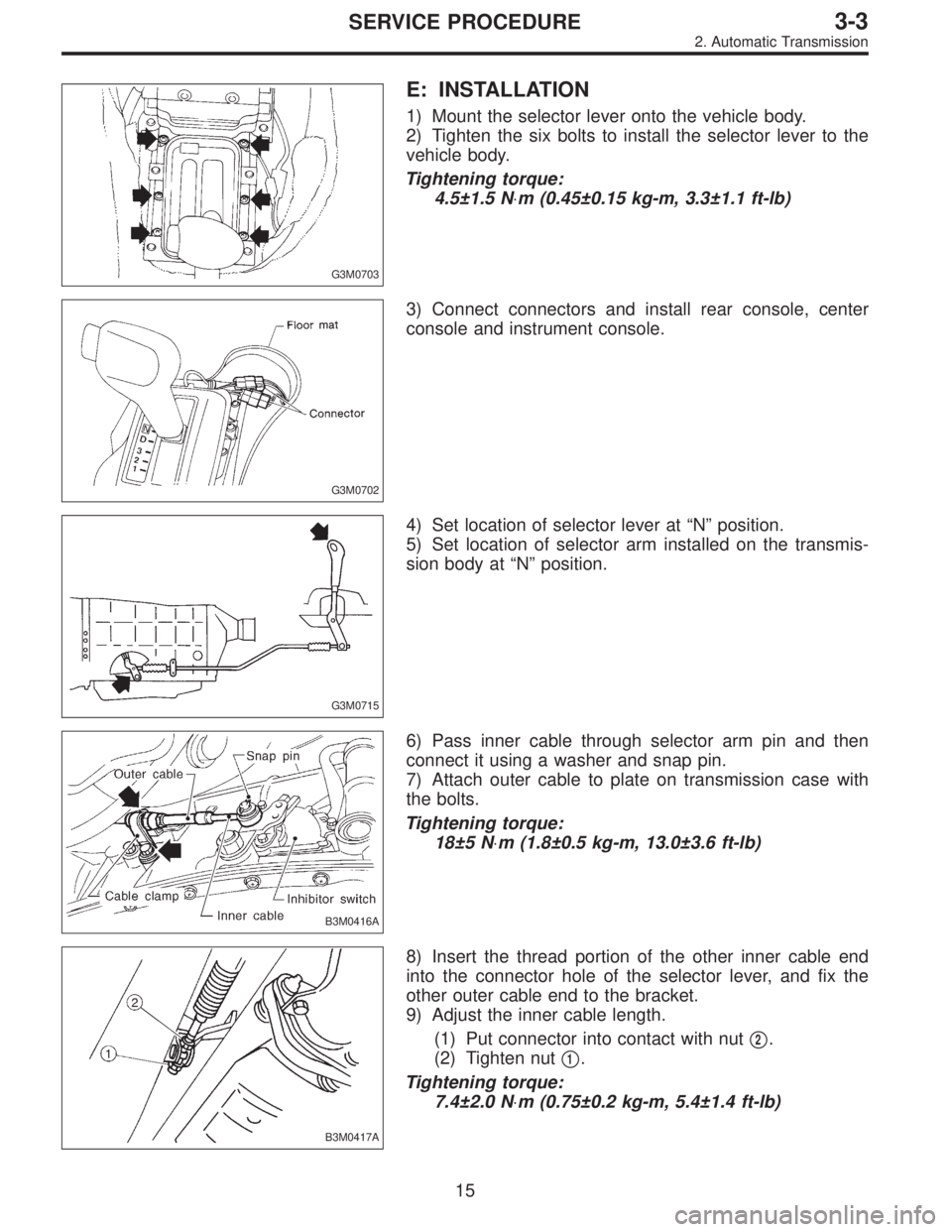
1) Mount the selector lever onto the vehicle body.
2) Tighten the six bolts to install the selector lever to the
vehicle body.
Tightening torque:
4.5±1.5 N⋅m (0.45±0.15 kg-m, 3.3±1.1 ft-lb)
G3M0702
3) Connect connectors and install rear console, center
console and instrument console.
G3M0715
4) Set location of selector lever at“N”position.
5) Set location of selector arm installed on the transmis-
sion body at“N”position.
B3M0416A
6) Pass inner cable through selector arm pin and then
connect it using a washer and snap pin.
7) Attach outer cable to plate on transmission case with
the bolts.
Tightening torque:
18±5 N⋅m (1.8±0.5 kg-m, 13.0±3.6 ft-lb)
B3M0417A
8) Insert the thread portion of the other inner cable end
into the connector hole of the selector lever, and fix the
other outer cable end to the bracket.
9) Adjust the inner cable length.
(1) Put connector into contact with nut�
2.
(2) Tighten nut�
1.
Tightening torque:
7.4±2.0 N⋅m (0.75±0.2 kg-m, 5.4±1.4 ft-lb)
15
3-3SERVICE PROCEDURE
2. Automatic Transmission
Page 1644 of 3342
1) Remove front seats.
2) Remove rear seat cushion.
3) Remove console box.
4) Remove front pillar lower trim panel.
5) Remove center pillar lower trim panel.
6) Remove side sill cover.
7) Remove fuel opener cover.
G5M0368
8) Remove clip under front seat.
9) Remove clip in toe board area.
NOTE:
When pulling out edge, do not pull mat alone; pull mat
together with edge.
Pry off two steel clips on side sill front cover and one on
side sill rear cover using screwdriver.
10) Remove mat hook.
11) Remove mat from toe board area.
12) Remove mat from heater module.
13) Roll mat, and take it out of opened rear door.
14) Installation is in the reverse order of removal.
NOTE:
�Secure mat firmly with hook and velcro tape.
�Insert mat edge firmly into the groove of side sill cover.
16
5-3SERVICE PROCEDURE
5. Inner Trim Panel
Page 1790 of 3342
B6M0144A
3. SUNROOF RELAY
Check continuity between terminals as indicated in table
below, when battery voltage is applied between terminals
No. 1 and No. 3.
When current flows. Between terminals
No. 2 and No. 4Continuity exists.
When current does not flow. Between terminals
No. 2 and No. 4Continuity does not
exist.
Between terminals
No. 1 and No. 3Continuity exists.
B6M0354
20. Radio, Speaker and Antenna
A: REMOVAL AND INSTALLATION
1. RADIO BODY
1) Remove hand brake cover.
2) Remove console cover.
3) Remove screws which secure center panel. Remove
center panel.
B6M0355
4) Remove fitting screws, and slightly pull radio out of
instrument panel.
5) Disconnect connectors and antenna feeder cord.
B6M0146
2. FRONT SPEAKER
1) Remove gusset speaker from behind the rearview mir-
ror while disconnecting connector.
2) Remove door trim panel.
46
6-2SERVICE PROCEDURE
19. Sunroof - 20. Radio, Speaker and Antenna
Page 1791 of 3342
B6M0144A
3. SUNROOF RELAY
Check continuity between terminals as indicated in table
below, when battery voltage is applied between terminals
No. 1 and No. 3.
When current flows. Between terminals
No. 2 and No. 4Continuity exists.
When current does not flow. Between terminals
No. 2 and No. 4Continuity does not
exist.
Between terminals
No. 1 and No. 3Continuity exists.
B6M0354
20. Radio, Speaker and Antenna
A: REMOVAL AND INSTALLATION
1. RADIO BODY
1) Remove hand brake cover.
2) Remove console cover.
3) Remove screws which secure center panel. Remove
center panel.
B6M0355
4) Remove fitting screws, and slightly pull radio out of
instrument panel.
5) Disconnect connectors and antenna feeder cord.
B6M0146
2. FRONT SPEAKER
1) Remove gusset speaker from behind the rearview mir-
ror while disconnecting connector.
2) Remove door trim panel.
46
6-2SERVICE PROCEDURE
19. Sunroof - 20. Radio, Speaker and Antenna
Page 1887 of 3342
OBD0057A
C: SUBARU SELECT MONITOR
1. HOW TO USE SUBARU SELECT MONITOR
1) Prepare Subaru select monitor and cartridge.
ST1 498307500 SELECT MONITOR KIT
ST2 498346300 CARTRIDGE
G3M0150
2) Turn ignition switch and Subaru select monitor switch to
OFF.
3) Insert cartridge into Subaru select monitor.
OBD0059B
B2M0829B
4) Connect Subaru select monitor to data link connector.
�Using data link connector for Subaru select monitor
only, connect Subaru select monitor to its data link con-
nector located in the lower portion of the instrument
panel (on the driver’s side), to the side of the center
console box.
OBD0669A
�Using data link connector for Subaru select monitor
and OBD-II general scan tool;
(1) Connect ST to Subaru select monitor cable.
ST 498357200 ADAPTER CABLE
36
2-7ON-BOARD DIAGNOSTICS II SYSTEM
3. Diagnosis System
Page 1918 of 3342
G3M0150
3) Insert cartridge into Subaru select monitor.
OBD0005H
B2M0432D
4) Connect test mode connector at the lower portion of
instrument panel (on the driver’s side), to the side of the
center console box.
OBD0059B
B2M0829B
5) Connect Subaru select monitor to data link connector.
�Using data link connector for Subaru select monitor only:
Connect Subaru select monitor to its data link connector
located in the lower portion of the instrument panel (on the
driver’s side), to the side of the center console box.
67
2-7ON-BOARD DIAGNOSTICS II SYSTEM
3. Diagnosis System
Page 1920 of 3342

NOTE:
�On AWD vehicles, release the parking brake.
�The speed difference between front and rear wheels
may light either the ABS or the ABS/TCS warning light, but
this indicates no malfunctions. When engine control diag-
nosis is finished, perform the ABS or the ABS/TCS memory
clearance procedure of self-diagnosis system.
4-4b [T6D2] or [T9K0], or 4-4c [T6D2] or [T9J0], or 4-4d
[T6D2] or [T9J0].>
OBD0005H
B2M0432D
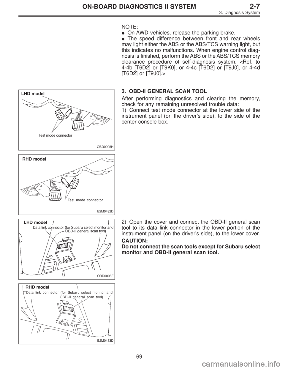
3. OBD-II GENERAL SCAN TOOL
After performing diagnostics and clearing the memory,
check for any remaining unresolved trouble data:
1) Connect test mode connector at the lower side of the
instrument panel (on the driver’s side), to the side of the
center console box.
OBD0006F
B2M0433D
2) Open the cover and connect the OBD-II general scan
tool to its data link connector in the lower portion of the
instrument panel (on the driver’s side), to the lower cover.
CAUTION:
Do not connect the scan tools except for Subaru select
monitor and OBD-II general scan tool.
69
2-7ON-BOARD DIAGNOSTICS II SYSTEM
3. Diagnosis System
Page 1923 of 3342
G3M0150
3) Insert cartridge into Subaru select monitor.
OBD0005H
B2M0432D
4) Connect test mode connector at the lower portion of
instrument panel (on the driver’s side), to the side of the
center console box.
OBD0059B
B2M0829B
5) Connect Subaru select monitor to data link connector.
�Using data link connector for Subaru select monitor only:
Connect Subaru select monitor to its data link connector
located in the lower portion of the instrument panel (on the
driver’s side), to the side of the center console box.
72
2-7ON-BOARD DIAGNOSTICS II SYSTEM
3. Diagnosis System