Page 1208 of 3342
![SUBARU LEGACY 1997 Service Repair Manual �Make adjustment so that steering wheel can be rotated
fully from lock to lock without binding.
9) Check for service limit as per article of“Service limit”.
<Ref. to 4-3 [W3C1].> Make replacement SUBARU LEGACY 1997 Service Repair Manual �Make adjustment so that steering wheel can be rotated
fully from lock to lock without binding.
9) Check for service limit as per article of“Service limit”.
<Ref. to 4-3 [W3C1].> Make replacement](/manual-img/17/57434/w960_57434-1207.png)
�Make adjustment so that steering wheel can be rotated
fully from lock to lock without binding.
9) Check for service limit as per article of“Service limit”.
Make replacement and adjustment
if necessary.
10) Install boot and mounting rubber to housing.
NOTE:
Apply grease through small hole in boot.
G4M0123
11) Fit clip (large) to boot, and then install boot to gearbox
while holding boot flange.
After installing boot, fold back boot flange to the extent that
large clip can not be seen.
NOTE:
�Before installing boot, be sure to apply grease to the
groove of tie-rod.
�Install fitting portions of boots to the following portions in
both sides of assembled steering gearbox.
1. The groove on gearbox
2. The groove on the rod
�Make sure that boot is installed without unusual inflation
or deflation.
G4M0124
12) Turn boot until it seats well on gearbox and rubber
mounting, then bend boot flange back.
G4M0125
13) Fix boot end with clip (small).
CAUTION:
Use screwdriver with blunted tip to prevent boot from
damage, when installing.
NOTE:
After installing, check boot end is positioned into groove on
tie-rod.
24
4-3SERVICE PROCEDURE
3. Steering Gearbox (Power Steering System) [LHD model]
Page 1220 of 3342

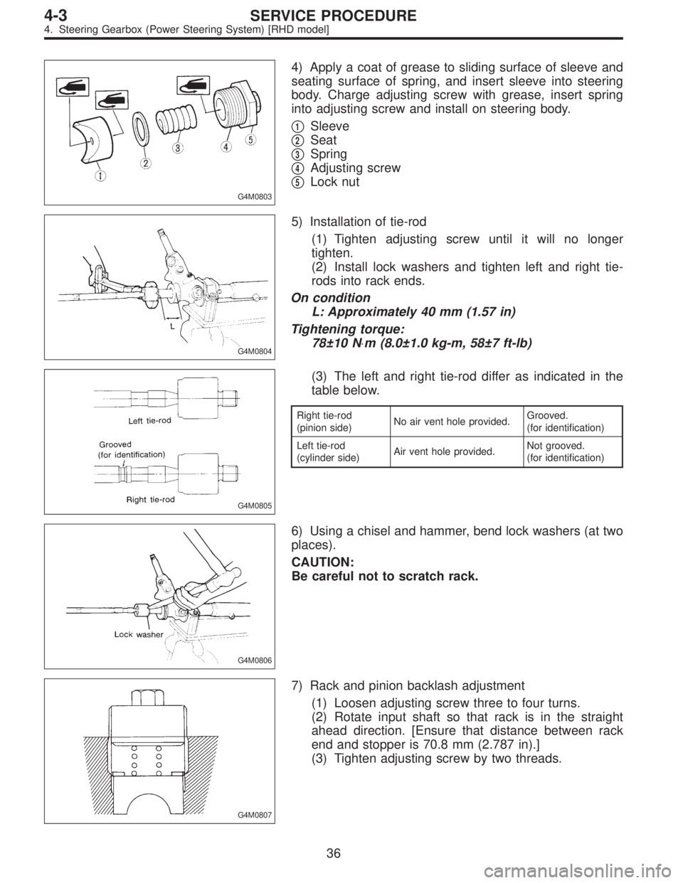
G4M0803
4) Apply a coat of grease to sliding surface of sleeve and
seating surface of spring, and insert sleeve into steering
body. Charge adjusting screw with grease, insert spring
into adjusting screw and install on steering body.
�
1Sleeve
�
2Seat
�
3Spring
�
4Adjusting screw
�
5Lock nut
G4M0804
5) Installation of tie-rod
(1) Tighten adjusting screw until it will no longer
tighten.
(2) Install lock washers and tighten left and right tie-
rods into rack ends.
On condition
L: Approximately 40 mm (1.57 in)
Tightening torque:
78±10 N⋅m (8.0±1.0 kg-m, 58±7 ft-lb)
G4M0805
(3) The left and right tie-rod differ as indicated in the
table below.
Right tie-rod
(pinion side)No air vent hole provided.Grooved.
(for identification)
Left tie-rod
(cylinder side)Air vent hole provided.Not grooved.
(for identification)
G4M0806
6) Using a chisel and hammer, bend lock washers (at two
places).
CAUTION:
Be careful not to scratch rack.
G4M0807
7) Rack and pinion backlash adjustment
(1) Loosen adjusting screw three to four turns.
(2) Rotate input shaft so that rack is in the straight
ahead direction. [Ensure that distance between rack
end and stopper is 70.8 mm (2.787 in).]
(3) Tighten adjusting screw by two threads.
36
4-3SERVICE PROCEDURE
4. Steering Gearbox (Power Steering System) [RHD model]
Page 1545 of 3342

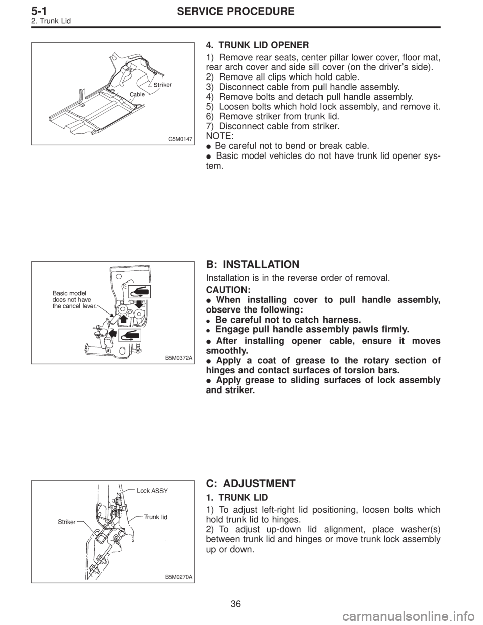
G5M0147
4. TRUNK LID OPENER
1) Remove rear seats, center pillar lower cover, floor mat,
rear arch cover and side sill cover (on the driver’s side).
2) Remove all clips which hold cable.
3) Disconnect cable from pull handle assembly.
4) Remove bolts and detach pull handle assembly.
5) Loosen bolts which hold lock assembly, and remove it.
6) Remove striker from trunk lid.
7) Disconnect cable from striker.
NOTE:
�Be careful not to bend or break cable.
�Basic model vehicles do not have trunk lid opener sys-
tem.
B5M0372A
B: INSTALLATION
Installation is in the reverse order of removal.
CAUTION:
�When installing cover to pull handle assembly,
observe the following:
�Be careful not to catch harness.
�Engage pull handle assembly pawls firmly.
�After installing opener cable, ensure it moves
smoothly.
�Apply a coat of grease to the rotary section of
hinges and contact surfaces of torsion bars.
�Apply grease to sliding surfaces of lock assembly
and striker.
B5M0270A
C: ADJUSTMENT
1. TRUNK LID
1) To adjust left-right lid positioning, loosen bolts which
hold trunk lid to hinges.
2) To adjust up-down lid alignment, place washer(s)
between trunk lid and hinges or move trunk lock assembly
up or down.
36
5-1SERVICE PROCEDURE
2. Trunk Lid
Page 1745 of 3342

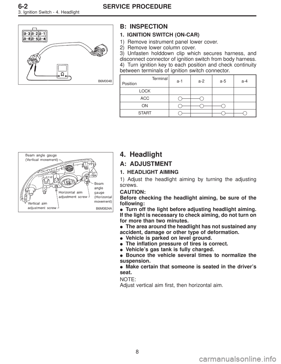
B6M0048
B: INSPECTION
1. IGNITION SWITCH (ON-CAR)
1) Remove instrument panel lower cover.
2) Remove lower column cover.
3) Unfasten holddown clip which secures harness, and
disconnect connector of ignition switch from body harness.
4) Turn ignition key to each position and check continuity
between terminals of ignition switch connector.
Terminal
Positiona-1 a-2 a-5 a-4
LOCK
ACC��
ON���
START���
B6M0824A
4. Headlight
A: ADJUSTMENT
1. HEADLIGHT AIMING
1) Adjust the headlight aiming by turning the adjusting
screws.
CAUTION:
Before checking the headlight aiming, be sure of the
following:
�Turn off the light before adjusting headlight aiming.
If the light is necessary to check aiming, do not turn on
for more than two minutes.
�The area around the headlight has not sustained any
accident, damage or other type of deformation.
�Vehicle is parked on level ground.
�The inflation pressure of tires is correct.
�Vehicle’s gas tank is fully charged.
�Bounce the vehicle several times to normalize the
suspension.
�Make certain that someone is seated in the driver’s
seat.
NOTE:
Adjust vertical aim first, then horizontal aim.
8
6-2SERVICE PROCEDURE
3. Ignition Switch - 4. Headlight
Page 1746 of 3342

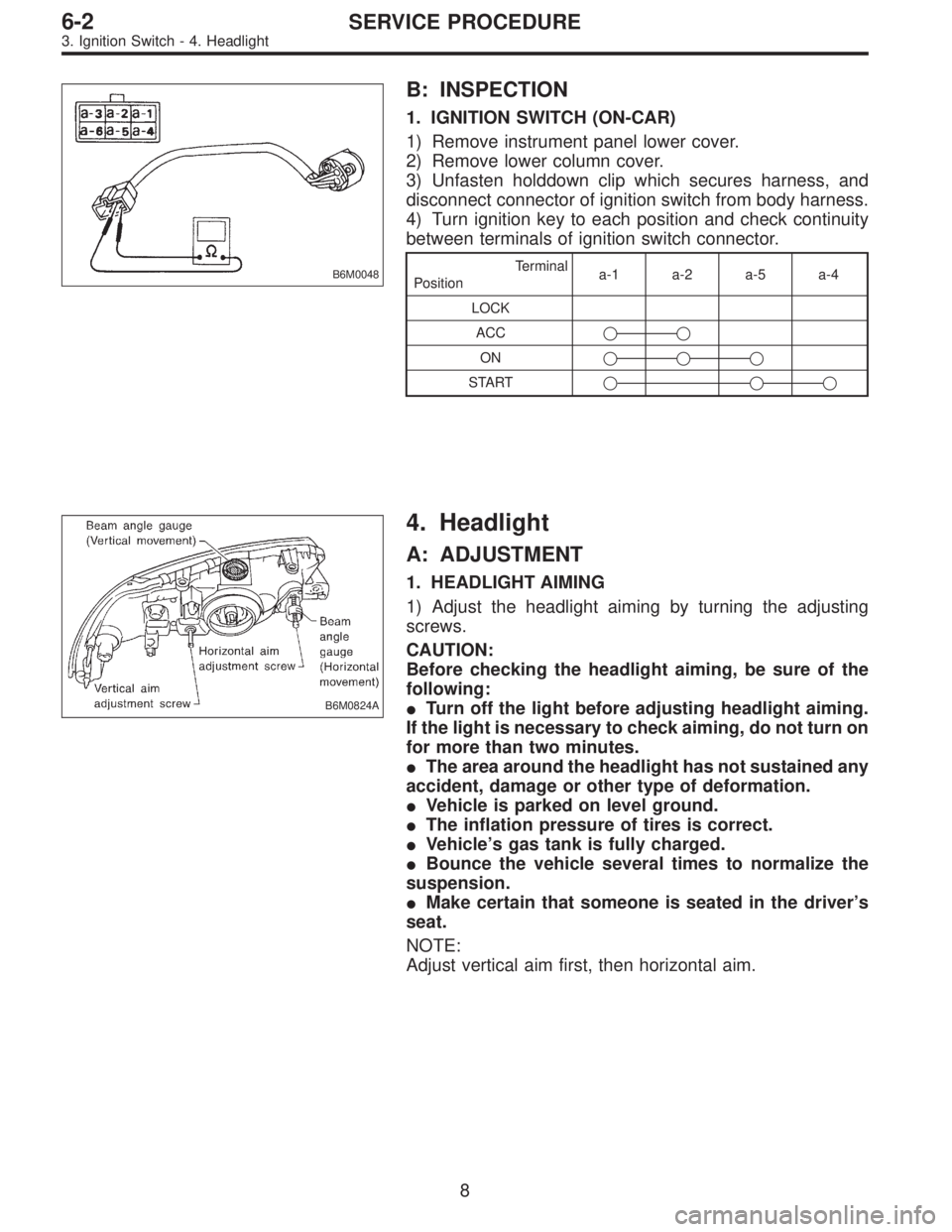
B6M0048
B: INSPECTION
1. IGNITION SWITCH (ON-CAR)
1) Remove instrument panel lower cover.
2) Remove lower column cover.
3) Unfasten holddown clip which secures harness, and
disconnect connector of ignition switch from body harness.
4) Turn ignition key to each position and check continuity
between terminals of ignition switch connector.
Terminal
Positiona-1 a-2 a-5 a-4
LOCK
ACC��
ON���
START���
B6M0824A
4. Headlight
A: ADJUSTMENT
1. HEADLIGHT AIMING
1) Adjust the headlight aiming by turning the adjusting
screws.
CAUTION:
Before checking the headlight aiming, be sure of the
following:
�Turn off the light before adjusting headlight aiming.
If the light is necessary to check aiming, do not turn on
for more than two minutes.
�The area around the headlight has not sustained any
accident, damage or other type of deformation.
�Vehicle is parked on level ground.
�The inflation pressure of tires is correct.
�Vehicle’s gas tank is fully charged.
�Bounce the vehicle several times to normalize the
suspension.
�Make certain that someone is seated in the driver’s
seat.
NOTE:
Adjust vertical aim first, then horizontal aim.
8
6-2SERVICE PROCEDURE
3. Ignition Switch - 4. Headlight