Page 255 of 3342
 Disconnect battery cables, and then remove bat-
tery and battery carrier.
(2) Disconnect washer motor connectors.
(3) Disconnect rear window glass washer hose")
�When inspecting #2 and #4 cylinders;
(1) Disconnect battery cables, and then remove bat-
tery and battery carrier.
(2) Disconnect washer motor connectors.
(3) Disconnect rear window glass washer hose from
washer motor, then plug connection with a suitable cap.
(4) Remove the two bolts which holds washer tank,
then secure the tank away from working area.
(5) Disconnect spark plug cords from spark plugs (#2
and #4 cylinders).
(6) Remove under cover (LH).
(7) Place suitable container under the vehicle.
(8) Disconnect PCV hose from rocker cover (LH).
(9) Remove bolts, then remove rocker cover (LH).
B2M1228A
5) Set #1 cylinder piston to top dead center of compres-
sion stroke by rotating crankshaft pulley clockwise.
NOTE:
When arrow mark on camshaft sprocket (RH) comes
exactly to the top, #1 cylinder piston is brought to the top
dead center of compression stroke.
B2M1229A
6) Measure #1 cylinder valve clearance by using thickness
gauge.
CAUTION:
�Insert the thickness gauge in as horizontal a direc-
tion as possible with respect to the valve stem end
face.
�Measure exhaust valve clearances while lifting-up
the vehicle.
Valve clearance:
Intake: 0.20±0.02 mm (0.0079±0.0008 in)
Exhaust: 0.25±0.02 mm (0.0098±0.0008 in)
7) If necessary, adjust the valve clearance.
[07B1].>
10
2-2
7. Valve Clearance
Page 256 of 3342
 Similar to measurement procedures used for #1
cylinder, measure #2, #3 and #4 cylinder valve clearances.
NOTE:
�Be sure to set cylinder pistons to their respective top
dead centers on comp")
B2M1230A
8) Similar to measurement procedures used for #1
cylinder, measure #2, #3 and #4 cylinder valve clearances.
NOTE:
�Be sure to set cylinder pistons to their respective top
dead centers on compression stroke before measuring
valve clearances.
�To set #3, #2 and #4 cylinder pistons to their top dead
centers on compression stroke, turn crankshaft pulley
clockwise 90°at a time starting with arrow mark on right-
hand camshaft sprocket facing up.
9) After inspection, install the related parts in the reverse
order of removal.
2. 2500 cc MODEL
CAUTION:
Inspection and adjustment of valve clearance should
be performed while engine is cold.
1) Set the vehicle onto the lift.
2) Disconnect battery ground cable.
3) Remove canister.
4) Remove one bolt which secures timing belt cover (RH).
5) Lift-up the vehicle.
6) Remove under cover (RH).
7) Remove canister bracket.
8) Loosen remaining bolts which secure timing belt cover
(RH), then remove belt cover.
9) Lower the vehicle.
B2M1225A
10) Remove rocker cover.
�When inspecting #1 and #3 cylinders;
(1) Disconnect connector from mass air flow sensor.
11
2-2
7. Valve Clearance
Page 258 of 3342
 Turn crankshaft pulley clockwise until arrow mark on
camshaft sprocket is set to position shown in figure.
12) Measure #1 cylinder intake valve and #3 cylinder
exhaust valve clea")
B2M1233A
B2M1234A
11) Turn crankshaft pulley clockwise until arrow mark on
camshaft sprocket is set to position shown in figure.
12) Measure #1 cylinder intake valve and #3 cylinder
exhaust valve clearances by using thickness gauge.
CAUTION:
�Insert the thickness gauge in as horizontal a direc-
tion as possible with respect to the shim.
�Measure exhaust valve clearances while lifting-up
the vehicle.
Valve clearance:
Intake: 0.20±0.02 mm (0.0079±0.0008 in)
Exhaust: 0.25±0.02 mm (0.0098±0.0008 in)
13) If necessary, adjust the valve clearance.
[07B2].>
B2M1235A
14) Further turn crankshaft pulley clockwise. Using the
same procedures as in step 12) above, measure valve
clearances.
(1) Set arrow mark on camshaft sprocket to position
shown in figure, and measure #2 cylinder exhaust valve
and #3 cylinder intake valve clearances.
B2M1236A
(2) Set arrow mark on camshaft sprocket to position
shown in figure, and measure #2 cylinder intake valve
and #4 cylinder exhaust valve clearances.
B2M1237A
(3) Set arrow mark on camshaft sprocket to position
shown in figure, and measure #1 cylinder exhaust valve
and #4 cylinder intake valve clearances.
15) After inspection, install the related parts in the reverse
order of removal.
13
2-2
7. Valve Clearance
Page 259 of 3342
 Set #1 cylinder piston to top dead center of compres-
sion stroke by rotatin")
B2M1228A
B: ADJUSTMENT
1. 2200 cc MODEL
CAUTION:
Adjustment of valve clearance should be performed
while engine is cold.
1) Set #1 cylinder piston to top dead center of compres-
sion stroke by rotating crankshaft pulley clockwise.
NOTE:
When arrow mark on camshaft sprocket (RH) comes
exactly to the top, #1 cylinder piston is brought to the top
dead center of compression stroke.
B2M1238A
2) Adjust the #1 cylinder valve clearance.
(1) Loosen the valve rocker nut and screw.
(2) Place suitable thickness gauge.
(3) While noting valve clearance, tighten valve rocker
adjust screw.
(4) When specified valve clearance is obtained, tighten
valve rocker nut.
Tightening torque:
10±1 N⋅m (1.0±0.1 kg-m, 7.2±0.7 ft-lb)
CAUTION:
�Insert the thickness gauge in as horizontal a direc-
tion as possible with respect to the valve stem end
face.
�Adjust exhaust valve clearances while lifting-up the
vehicle.
Valve clearance:
Intake: 0.20±0.02 mm (0.0079±0.0008 in)
Exhaust: 0.25±0.02 mm (0.0098±0.0008 in)
3) Ensure that valve clearances are within specifications.
4) Turn crankshaft two complete rotations until #1 cylinder
piston is again set to top dead center on compression
stroke.
5) Ensure that valve clearances are within specifications.
If necessary, re-adjust valve clearances.
14
2-2
7. Valve Clearance
Page 260 of 3342
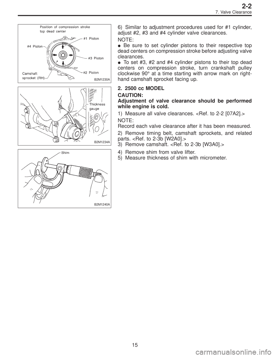
B2M1230A
6) Similar to adjustment procedures used for #1 cylinder,
adjust #2, #3 and #4 cylinder valve clearances.
NOTE:
�Be sure to set cylinder pistons to their respective top
dead centers on compression stroke before adjusting valve
clearances.
�To set #3, #2 and #4 cylinder pistons to their top dead
centers on compression stroke, turn crankshaft pulley
clockwise 90°at a time starting with arrow mark on right-
hand camshaft sprocket facing up.
B2M1234A
2. 2500 cc MODEL
CAUTION:
Adjustment of valve clearance should be performed
while engine is cold.
1) Measure all valve clearances.
NOTE:
Record each valve clearance after it has been measured.
2) Remove timing belt, camshaft sprockets, and related
parts.
3) Remove camshaft.
B2M1240A
4) Remove shim from valve lifter.
5) Measure thickness of shim with micrometer.
15
2-2
7. Valve Clearance
Page 262 of 3342
 Turn crankshaft pulley clockwise until arrow mark on
camshaft sprocket is set to position shown in figure.
11) Ensure that #1 cylinder intake valve and #3 cylinder
exhaust valve")
B2M1233A
B2M1234A
10) Turn crankshaft pulley clockwise until arrow mark on
camshaft sprocket is set to position shown in figure.
11) Ensure that #1 cylinder intake valve and #3 cylinder
exhaust valve are adjusted to specifications.
CAUTION:
�Insert the thickness gauge in as horizontal a direc-
tion as possible with respect to the shim.
�Adjust exhaust valve clearances while lifting-up the
vehicle.
Valve clearance:
Intake: 0.20±0.02 mm (0.0079±0.0008 in)
Exhaust: 0.25±0.02 mm (0.0098±0.0008 in)
12) Turn crankshaft two complete rotations. Check again
to ensure that #1 cylinder intake valve and #3 cylinder
exhaust valve clearances are within specifications. If
necessary, re-adjust valve clearances.
B2M1235A
13) Further turn crankshaft pulley clockwise. Using the
same procedures as in step 11) above, measure valve
clearances.
(1) Set arrow mark on camshaft sprocket to position
shown in figure, and check #2 cylinder exhaust valve
and #3 cylinder intake valve clearances.
B2M1236A
(2) Set arrow mark on camshaft sprocket to position
shown in figure, and check #2 cylinder intake valve and
#4 cylinder exhaust valve clearances.
B2M1237A
(3) Set arrow mark on camshaft sprocket to position
shown in figure, and check #1 cylinder exhaust valve
and #4 cylinder intake valve clearances.
17
2-2
7. Valve Clearance
Page 306 of 3342
B2M0077A
(6) Check the valve guide protrusion.
Valve guide protrusion: L
17.5—18.0 mm (0.689—0.709 in)
B2M0078
(7) Ream the inside of valve guide with ST. Gently
rotate the reamer clockwise while pressing it lightly into
valve guide, and return it also rotating clockwise. After
reaming, clean valve guide to remove chips.
ST 499767400 VALVE GUIDE REAMER
CAUTION:
�Apply engine oil to the reamer when reaming.
�If the inner surface of the valve guide is torn, the
edge of the reamer should be slightly ground with an
oil stone.
�If the inner surface of the valve guide becomes lus-
trous and the reamer does not chips, use a new reamer
or remedy the reamer.
(8) Recheck the contact condition between valve and
valve seat after replacing valve guide.
43
2-3SERVICE PROCEDURE
6. Cylinder Head
Page 365 of 3342
G2M0728
1) Crankshaft and camshaft sprocket alignment
(1) Align mark on crankshaft sprocket with mark on the
oil pump cover at cylinder block.
B2M0694A
(2) Align single line mark on right-hand exhaust cam-
shaft sprocket with notch on belt cover.
B2M0695A
(3) Align single line mark on right-hand exhaust cam-
shaft sprocket with notch on belt cover.
(Make sure double lines on intake camshaft and
exhaust camshaft sprockets are aligned.)
B2M0696A
(4) Align single line mark on left-hand exhaust cam-
shaft sprocket with notch on belt cover by turning
sprocket counter-clockwise (as viewed from front of
engine).
B2M0697A
(5) Align single line mark on left-hand intake camshaft
sprocket with notch on belt cover by turning sprocket
clockwise (as viewed from front of engine).
Ensure double lines on intake and exhaust camshaft
sprockets are aligned.
24
2-3bSERVICE PROCEDURE
2. Timing Belt
 Check the valve guide protrusion.
Valve guide protrusion: L
17.5—18.0 mm (0.689—0.709 in)
B2M0078
(7) Ream the inside of valve guide with ST. Gently
rotate the reamer clockwise while")
 Crankshaft and camshaft sprocket alignment
(1) Align mark on crankshaft sprocket with mark on the
oil pump cover at cylinder block.
B2M0694A
(2) Align single line mark on right-hand exhaust")