Page 1709 of 3342

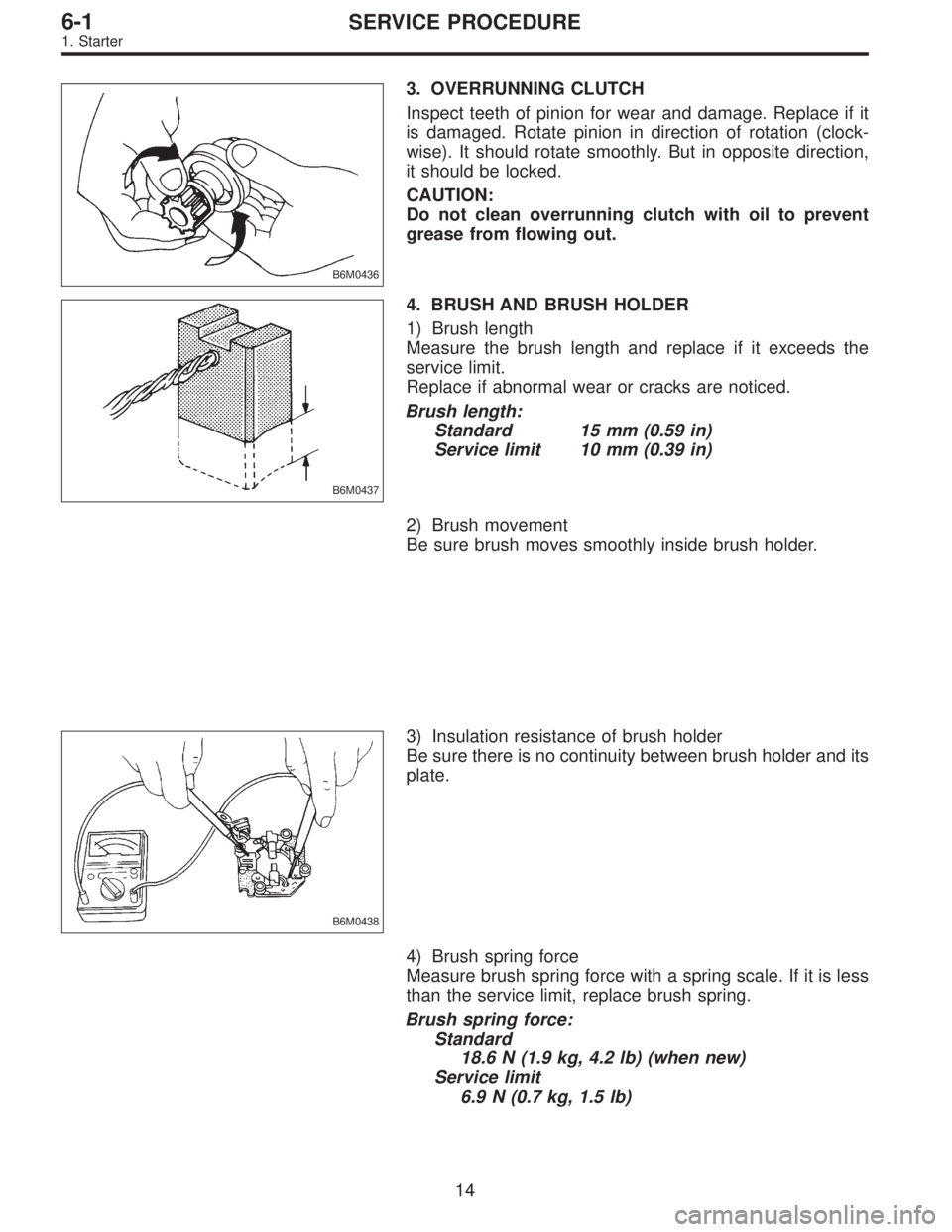
B6M0436
3. OVERRUNNING CLUTCH
Inspect teeth of pinion for wear and damage. Replace if it
is damaged. Rotate pinion in direction of rotation (clock-
wise). It should rotate smoothly. But in opposite direction,
it should be locked.
CAUTION:
Do not clean overrunning clutch with oil to prevent
grease from flowing out.
B6M0437
4. BRUSH AND BRUSH HOLDER
1) Brush length
Measure the brush length and replace if it exceeds the
service limit.
Replace if abnormal wear or cracks are noticed.
Brush length:
Standard 15 mm (0.59 in)
Service limit 10 mm (0.39 in)
2) Brush movement
Be sure brush moves smoothly inside brush holder.
B6M0438
3) Insulation resistance of brush holder
Be sure there is no continuity between brush holder and its
plate.
4) Brush spring force
Measure brush spring force with a spring scale. If it is less
than the service limit, replace brush spring.
Brush spring force:
Standard
18.6 N (1.9 kg, 4.2 lb) (when new)
Service limit
6.9 N (0.7 kg, 1.5 lb)
14
6-1SERVICE PROCEDURE
1. Starter
Page 1779 of 3342

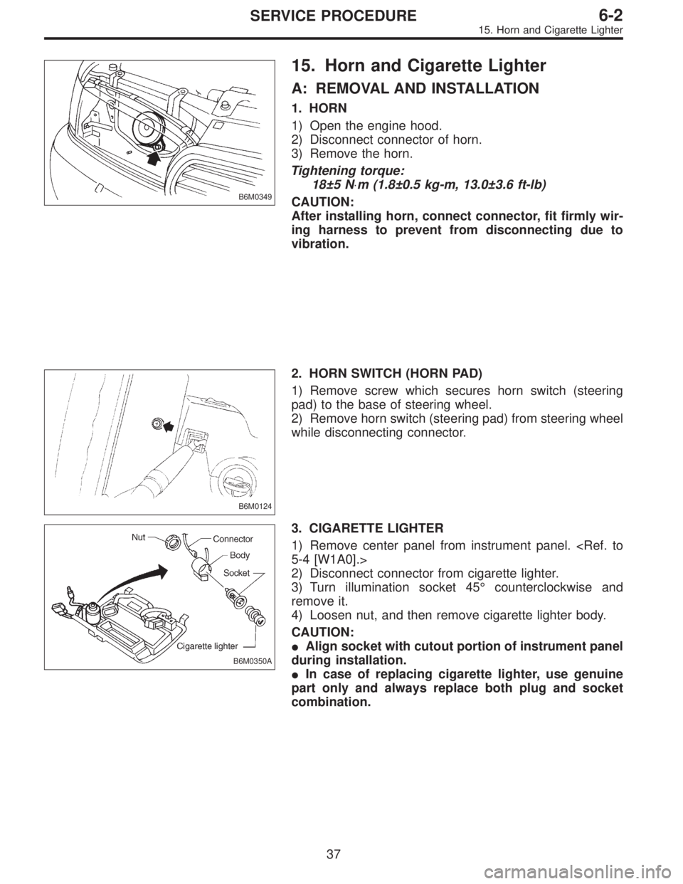
B6M0349
15. Horn and Cigarette Lighter
A: REMOVAL AND INSTALLATION
1. HORN
1) Open the engine hood.
2) Disconnect connector of horn.
3) Remove the horn.
Tightening torque:
18±5 N⋅m (1.8±0.5 kg-m, 13.0±3.6 ft-lb)
CAUTION:
After installing horn, connect connector, fit firmly wir-
ing harness to prevent from disconnecting due to
vibration.
B6M0124
2. HORN SWITCH (HORN PAD)
1) Remove screw which secures horn switch (steering
pad) to the base of steering wheel.
2) Remove horn switch (steering pad) from steering wheel
while disconnecting connector.
B6M0350A
3. CIGARETTE LIGHTER
1) Remove center panel from instrument panel.
5-4 [W1A0].>
2) Disconnect connector from cigarette lighter.
3) Turn illumination socket 45°counterclockwise and
remove it.
4) Loosen nut, and then remove cigarette lighter body.
CAUTION:
�Align socket with cutout portion of instrument panel
during installation.
�In case of replacing cigarette lighter, use genuine
part only and always replace both plug and socket
combination.
37
6-2SERVICE PROCEDURE
15. Horn and Cigarette Lighter
Page 1883 of 3342

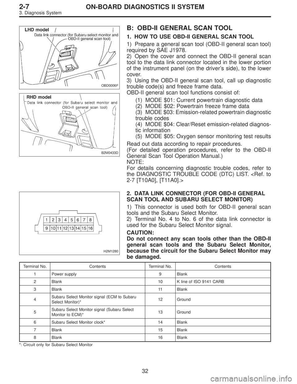
OBD0006F
B2M0433D
B: OBD-II GENERAL SCAN TOOL
1. HOW TO USE OBD-II GENERAL SCAN TOOL
1) Prepare a general scan tool (OBD-II general scan tool)
required by SAE J1978.
2) Open the cover and connect the OBD-II general scan
tool to the data link connector located in the lower portion
of the instrument panel (on the driver’s side), to the lower
cover.
3) Using the OBD-II general scan tool, call up diagnostic
trouble code(s) and freeze frame data.
OBD-II general scan tool functions consist of:
(1) MODE $01: Current powertrain diagnostic data
(2) MODE $02: Powertrain freeze frame data
(3) MODE $03: Emission-related powertrain diagnostic
trouble codes
(4) MODE $04: Clear/Reset emission-related diagnos-
tic information
(5) MODE $05: Oxygen sensor monitoring test results
Read out data according to repair procedures.
(For detailed operation procedures, refer to the OBD-II
General Scan Tool Operation Manual.)
NOTE:
For details concerning diagnostic trouble codes, refer to
the DIAGNOSTIC TROUBLE CODE (DTC) LIST.
2-7 [T10A0], [T11A0].>
H2M1280
2. DATA LINK CONNECTOR (FOR OBD-II GENERAL
SCAN TOOL AND SUBARU SELECT MONITOR)
1) This connector is used both for OBD-II general scan
tools and the Subaru Select Monitor.
2) Terminal No. 4 to No. 6 of the data link connector is
used for the Subaru Select Monitor signal.
CAUTION:
Do not connect any scan tools other than the OBD-II
general scan tools and the Subaru Select Monitor,
because the circuit for the Subaru Select Monitor may
be damaged.
Terminal No. Contents Terminal No. Contents
1 Power supply 9 Blank
2 Blank 10 K line of ISO 9141 CARB
3 Blank 11 Blank
4Subaru Select Monitor signal (ECM to Subaru
Select Monitor)*12 Ground
5Subaru Select Monitor signal (Subaru Select
Monitor to ECM)*13 Ground
6 Subaru Select Monitor clock* 14 Blank
7 Blank 15 Blank
8 Blank 16 Blank
*: Circuit only for Subaru Select Monitor
32
2-7ON-BOARD DIAGNOSTICS II SYSTEM
3. Diagnosis System