Page 1091 of 3342

Left side Right side
Toe-in is
increased.
B4M0191A
Turn adjusting
wheel
counterclockwise
and adjusting bolt
clockwise.
B4M0351A
Turn adjusting
wheel clockwise
and adjusting bolt
counterclockwise.
Toe-in is
decreased.
B4M0351A
Turn adjusting
wheel clockwise
and adjusting bolt
counterclockwise.
B4M0191A
Turn adjusting
wheel
counterclockwise
and adjusting bolt
clockwise.
G4M0485
NOTE:
�When left and right wheels are adjusted for toe-in at the
same time, moving one scale graduation changes toe-in by
approximately 4 mm (0.16 in).
�Turn adjusting wheel and adjusting bolt equally in oppo-
site directions so that same scale graduations are posi-
tioned directly above center of the adjusting bolt.
3) Tighten self-locking nut.
Tightening torque:
137±20 N⋅m (14±2 kg-m, 101±14 ft-lb)
M4A0059
5. REAR WHEEL TOE-IN (AWD MODEL)
�Inspection
1) Using a toe-in gauge, measure rear wheel toe-in.
Toe-in: 0±3 mm (0±0.12 in)
2) Mark rear sides of left and right tires at height corre-
sponding to center of spindles and measure distance“B”
between marks.
3) Move vehicle forward so that marks line up with front
sides at height corresponding to center of spindles.
4) Measure distance“A”between left and right marks.
Toe-in can then be obtained by the following equation:
B�A = Toe-in
12
4-1SERVICE PROCEDURE
1. On-car Services
Page 1092 of 3342
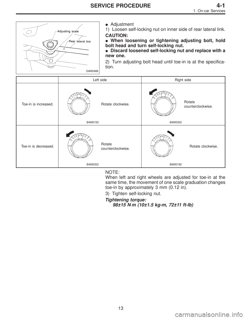
G4M0486
�Adjustment
1) Loosen self-locking nut on inner side of rear lateral link.
CAUTION:
�When loosening or tightening adjusting bolt, hold
bolt head and turn self-locking nut.
�Discard loosened self-locking nut and replace with a
new one.
2) Turn adjusting bolt head until toe-in is at the specifica-
tion.
Left side Right side
Toe-in is increased.
B4M0192
Rotate clockwise.
B4M0352
Rotate
counterclockwise.
Toe-in is decreased.
B4M0352
Rotate
counterclockwise.
B4M0192
Rotate clockwise.
NOTE:
When left and right wheels are adjusted for toe-in at the
same time, the movement of one scale graduation changes
toe-in by approximately 3 mm (0.12 in).
3) Tighten self-locking nut.
Tightening torque:
98±15 N⋅m (10±1.5 kg-m, 72±11 ft-lb)
13
4-1SERVICE PROCEDURE
1. On-car Services
Page 1114 of 3342
 Loosen wheel nuts. Lift-up vehicle and remove wheel.
2) Remove rear exhaust pipe and muffler.
3) Remove stabilizer link from rear lateral link.
4) Scribe an aligning mark on ad")
G4M0529
1. FWD MODEL
1) Loosen wheel nuts. Lift-up vehicle and remove wheel.
2) Remove rear exhaust pipe and muffler.
3) Remove stabilizer link from rear lateral link.
4) Scribe an aligning mark on adjusting bolt, adjusting
wheel and crossmember.
5) Remove bolts securing lateral links to housing.
6) Turn cap (lateral link) counterclockwise until it contacts
stopper, then remove cap.
7) While holding adjusting bolt’s head with a wrench,
loosen self-locking nut.
CAUTION:
Always loosen self-locking nut before turning adjust-
ing bolt.
8) Lateral link removal
(1) Left lateral links
Remove adjusting bolt and front and rear lateral links.
(2) Right lateral links
Support crossmember with transmission jack.
Remove bolts securing crossmember to vehicle body.
Lower transmission jack until adjusting bolt can be
removed. Remove adjusting bolt, front and rear lateral
links.
2. AWD MODEL
1) Loosen wheel nuts. Lift-up vehicle and remove wheel.
2) Remove stabilizers link from lateral link.
3) Remove A.B.S. sensor harness from trailing link.
(A.B.S. equipped models.)
B4M0573A
4) Remove bolt securing trailing link to housing.
5) Remove DOJ from differential.
6) Scribe an alignment mark on rear lateral link adjusting
bolt and crossmember.
7) Remove bolt securing lateral link to housing.
8) Remove bolts securing front and rear lateral links to
crossmember, detach lateral links.
CAUTION:
To loosen adjusting bolt, always loosen nut while hold-
ing the head of adjusting bolt.
35
4-1SERVICE PROCEDURE
8. Lateral Link
Page 1185 of 3342
 5.3 (17.4) 5.6 (18.4)
Steering angle (Inside-Outside) 37.6°—32.6°34.4°—30.2°
S")
1. Steering System
A: SPECIFICATIONS
Except OUTBACK model OUTBACK model
Whole systemMinimum turning radius m (ft) 5.3 (17.4) 5.6 (18.4)
Steering angle (Inside-Outside) 37.6°—32.6°34.4°—30.2°
Steering wheel diameter mm (in) 385 (15.16)
Overall gear ratio (Turns, lock to lock) 16.5 (3.2) 19 (3.4)
GearboxType Rack and pinion, Integral
Backlash 0 (Automatically adjustable)
Valve (Power steering system) Rotary valve
Pump (Power steering
system)Type Vane pump
Oil tank Installed on pump
Output cm
3(cu in)/rev. 7.2 (0.439)
Relief pressure kPa (kg/cm
2, psi) 7,355 (75, 1,067)
Hydraulic fluid controlDropping in response to increased engine
revolutions
Hydraulic fluid�(US qt, Imp qt)1,000 rpm: 7 (7.4, 6.2)
3,000 rpm: 5 (5.3, 4.4)
Range of revolution rpm 500—7,500
Revolving direction Clockwise
Working fluid (Power
steering system)Name ATF DEXRON II, IIE or III
Capacity Oil tank�(US qt, Imp qt)
Total0.35 (0.4, 0.3)
0.7 (0.7, 0.6)
2
4-3SPECIFICATIONS AND SERVICE DATA
1. Steering System
Page 1200 of 3342
A: REMOVAL
1) Disconnect battery minus terminal.
2) Loosen front wheel nut.
3) Lift vehicle and remove front wheels.
4) Remove front exhaust pipe assembly.
WARNING:
Be careful, exhaust pipe is hot.
G4M0097
5) Using a puller, remove tie-rod end from knuckle arm
after pulling off cotter pin and removing castle nut.
G4M0098
6) Remove jack-up plate and front stabilizer.
G4M0099
7) Remove one pipe joint at the center of gearbox, and
connect vinyl hose to pipe and joint. Discharge fluid by
turning steering wheel fully clockwise and counterclock-
wise. Discharge fluid similarly from the other pipe.
G4M0086
8) Remove lower side bolt of universal joint, then remove
upper side bolt and lift the joint upward.
NOTE:
Place a mark on the joint and mating serration so that they
can be re-installed at the original position.
16
4-3SERVICE PROCEDURE
3. Steering Gearbox (Power Steering System) [LHD model]
Page 1246 of 3342
G4M0098
7. Pipe Assembly (Power Steering
System)
A: REMOVAL
1. LHD MODEL
1) Disconnect battery minus terminal.
G4M0099
2) Lift vehicle and remove jack-up plate.
3) Remove one pipe joint at the center of gearbox, and
connect vinyl hose to pipe and joint. Discharge fluid by
turning steering wheel fully clockwise and counterclock-
wise. Discharge fluid similarly from the other pipe.
CAUTION:
Improper removal and installation of parts often
causes fluid leak trouble. To prevent this, clean the
surrounding portions before disassembly and
reassembly, and pay special attention to keep dirt and
other foreign matter from mating surfaces.
G4M0162
4) Remove clamp E from pipes C and D.
62
4-3SERVICE PROCEDURE
7. Pipe Assembly (Power Steering System)
Page 1247 of 3342
 Disconnect pipe C⋅D from pipe (on the gearbox side).
CAUTION:
�When disconnecting pipe C⋅D, use two wrenches to
prevent deformities.
�Be careful to keep pipe connections free from for-")
G4M0101
5) Disconnect pipe C⋅D from pipe (on the gearbox side).
CAUTION:
�When disconnecting pipe C⋅D, use two wrenches to
prevent deformities.
�Be careful to keep pipe connections free from for-
eign matter.
B4M1159A
6) Remove bolt A.
Disconnect pipe C from oil pump. Disconnect pipe D from
oil tank.
CAUTION:
�Do not allow fluid from the hose end to come into
contact with pulley belt.
�To prevent foreign matter from entering the hose
and pipe, cover the open ends of them with a clean
cloth.
G4M0098
2. RHD MODEL
1) Disconnect battery negative terminal.
B4M0671A
2) Lift vehicle and remove jack-up plate.
3) Remove one pipe joint at the center of gearbox, and
connect vinyl hose to pipe and joint. Discharge fluid by
turning steering wheel fully clockwise and counterclock-
wise. Discharge fluid similarly from the other pipe.
CAUTION:
Improper removal and installation of parts often
causes fluid leak trouble. To prevent this, clean the
surrounding portions before disassembly and
reassembly, and pay special attention to keep dirt and
other foreign matter from mating surfaces.
63
4-3SERVICE PROCEDURE
7. Pipe Assembly (Power Steering System)
Page 1270 of 3342
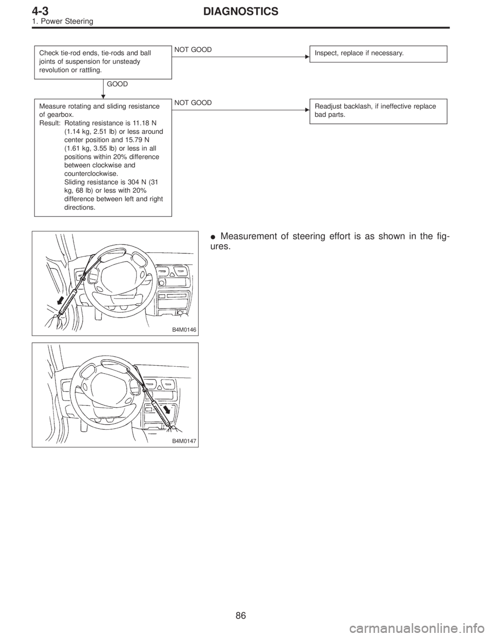
Check tie-rod ends, tie-rods and ball
joints of suspension for unsteady
revolution or rattling.
GOOD
�NOT GOOD
Inspect, replace if necessary.
Measure rotating and sliding resistance
of gearbox.
Result: Rotating resistance is 11.18 N
(1.14 kg, 2.51 lb) or less around
center position and 15.79 N
(1.61 kg, 3.55 lb) or less in all
positions within 20% difference
between clockwise and
counterclockwise.
Sliding resistance is 304 N (31
kg, 68 lb) or less with 20%
difference between left and right
directions.�NOT GOOD
Readjust backlash, if ineffective replace
bad parts.
B4M0146
�Measurement of steering effort is as shown in the fig-
ures.
B4M0147
�
86
4-3DIAGNOSTICS
1. Power Steering
 Disconnect battery minus terminal.
2) Loosen front wheel nut.
3) Lift vehicle and remove front wheels.
4) Remove front exhaust pipe assembly.
WARNING:
Be careful, exhaust pipe is hot.
G4")

A: REMOVAL
1. LHD MODEL
1) Disconnect battery minus terminal.
G4M0099
2) Lift vehicle and remove jack-up plate.
3) Remove one pipe joint at the center")