Page 374 of 3342
C: INSTALLATION
1. CAMSHAFT
B2M1304F
Tightening torque: N⋅m (kg-m, ft-lb)
T1: 5±0.5 (0.5±0.05, 3.6±0.4)
T2: 10±0.7 (1.0±0.07, 7.2±0.5)
T3: 20±2 (2.0±0.2, 14.5±1.4)
B2M1200A
1) Camshaft installation
Apply engine oil to cylinder head at camshaft bearing loca-
tion before installing camshaft. Install camshaft so that
rocker arm is close to or in contact with“base circle”of cam
lobe.
CAUTION:
�When camshafts are positioned as shown in figure,
camshafts need to be rotated at a minimum to align
with timing belt during installation.
�Right-hand camshaft need not be rotated when set
at position shown in figure.
Left-hand intake camshaft: Rotate 80°clockwise.
Left-hand exhaust camshaft: Rotate 45°counter-clock-
wise.
33
2-3bSERVICE PROCEDURE
3. Camshaft
Page 381 of 3342

G2M0762
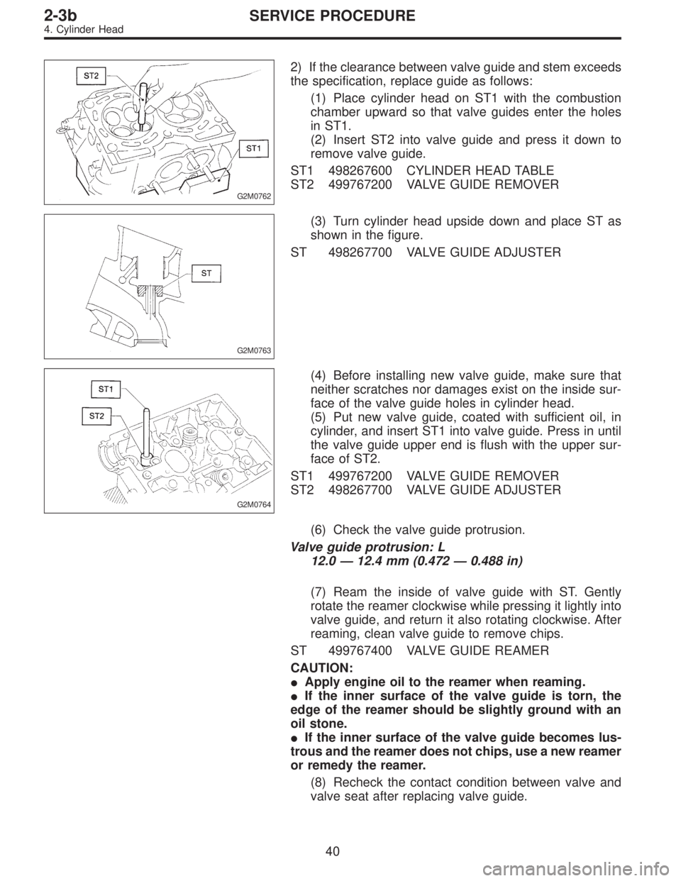
2) If the clearance between valve guide and stem exceeds
the specification, replace guide as follows:
(1) Place cylinder head on ST1 with the combustion
chamber upward so that valve guides enter the holes
in ST1.
(2) Insert ST2 into valve guide and press it down to
remove valve guide.
ST1 498267600 CYLINDER HEAD TABLE
ST2 499767200 VALVE GUIDE REMOVER
G2M0763
(3) Turn cylinder head upside down and place ST as
shown in the figure.
ST 498267700 VALVE GUIDE ADJUSTER
G2M0764
(4) Before installing new valve guide, make sure that
neither scratches nor damages exist on the inside sur-
face of the valve guide holes in cylinder head.
(5) Put new valve guide, coated with sufficient oil, in
cylinder, and insert ST1 into valve guide. Press in until
the valve guide upper end is flush with the upper sur-
face of ST2.
ST1 499767200 VALVE GUIDE REMOVER
ST2 498267700 VALVE GUIDE ADJUSTER
(6) Check the valve guide protrusion.
Valve guide protrusion: L
12.0—12.4 mm (0.472—0.488 in)
(7) Ream the inside of valve guide with ST. Gently
rotate the reamer clockwise while pressing it lightly into
valve guide, and return it also rotating clockwise. After
reaming, clean valve guide to remove chips.
ST 499767400 VALVE GUIDE REAMER
CAUTION:
�Apply engine oil to the reamer when reaming.
�If the inner surface of the valve guide is torn, the
edge of the reamer should be slightly ground with an
oil stone.
�If the inner surface of the valve guide becomes lus-
trous and the reamer does not chips, use a new reamer
or remedy the reamer.
(8) Recheck the contact condition between valve and
valve seat after replacing valve guide.
40
2-3bSERVICE PROCEDURE
4. Cylinder Head
Page 811 of 3342
G3M0484
9) Install the one-way clutch (1-2) and plate, and secure
with the snap ring.
NOTE:
Set the inner race. Make sure that the forward clutch is free
in the clockwise direction and locked in the counterclock-
wise direction, as viewed from the front of the vehicle.
G3M0911
12. One-way Clutch Outer Race
A: DISASSEMBLY
Remove the snap ring. Then remove the one-way clutch
(3-4).
B: INSPECTION
Check the sliding surface and one-way clutch (3-4) for any
harmful cuts, damage, or other faults.
G3M0486
C: ASSEMBLY
1) Assemble the one-way clutch (3-4), and secure with the
snap ring.
NOTE:
Pay attention to the orientation of the one-way clutch (3-4).
2) Assemble the rear internal gear, and secure the outer
race. Make sure that the internal gear is locked in the
clockwise direction, and free to rotate in the counterclock-
wise direction.
105
3-2SERVICE PROCEDURE
11. Forward Clutch Drum - 12. One-Way Clutch Outer Race
Page 911 of 3342
G3M0484
9) Install the one-way clutch (1-2) and plate, and secure
with the snap ring.
NOTE:
Set the inner race. Make sure that the forward clutch is free
in the clockwise direction and locked in the counterclock-
wise direction, as viewed from the front of the vehicle.
G3M0911
12. One-way Clutch Outer Race
A: DISASSEMBLY
Remove the snap ring. Then remove the one-way clutch
(3-4).
B: INSPECTION
Check the sliding surface and one-way clutch (3-4) for any
harmful cuts, damage, or other faults.
G3M0486
C: ASSEMBLY
1) Assemble the one-way clutch (3-4), and secure with the
snap ring.
NOTE:
Pay attention to the orientation of the one-way clutch (3-4).
2) Assemble the rear internal gear, and secure the outer
race. Make sure that the internal gear is locked in the
clockwise direction, and free to rotate in the counterclock-
wise direction.
105
3-2SERVICE PROCEDURE
11. Forward Clutch Drum - 12. One-Way Clutch Outer Race
Page 1013 of 3342
G3M0484
9) Install the one-way clutch (1-2) and plate, and secure
with the snap ring.
NOTE:
Set the inner race. Make sure that the forward clutch is free
in the clockwise direction and locked in the counterclock-
wise direction, as viewed from the front of the vehicle.
G3M0911
12. One-way Clutch Outer Race
A: DISASSEMBLY
Remove the snap ring. Then remove the one-way clutch
(3-4).
B: INSPECTION
Check the sliding surface and one-way clutch (3-4) for any
harmful cuts, damage, or other faults.
G3M0486
C: ASSEMBLY
1) Assemble the one-way clutch (3-4), and secure with the
snap ring.
NOTE:
Pay attention to the orientation of the one-way clutch (3-4).
2) Assemble the rear internal gear, and secure the outer
race. Make sure that the internal gear is locked in the
clockwise direction, and free to rotate in the counterclock-
wise direction.
105
3-2SERVICE PROCEDURE
11. Forward Clutch Drum - 12. One-Way Clutch Outer Race
Page 1014 of 3342
G3M0484
9) Install the one-way clutch (1-2) and plate, and secure
with the snap ring.
NOTE:
Set the inner race. Make sure that the forward clutch is free
in the clockwise direction and locked in the counterclock-
wise direction, as viewed from the front of the vehicle.
G3M0911
12. One-way Clutch Outer Race
A: DISASSEMBLY
Remove the snap ring. Then remove the one-way clutch
(3-4).
B: INSPECTION
Check the sliding surface and one-way clutch (3-4) for any
harmful cuts, damage, or other faults.
G3M0486
C: ASSEMBLY
1) Assemble the one-way clutch (3-4), and secure with the
snap ring.
NOTE:
Pay attention to the orientation of the one-way clutch (3-4).
2) Assemble the rear internal gear, and secure the outer
race. Make sure that the internal gear is locked in the
clockwise direction, and free to rotate in the counterclock-
wise direction.
105
3-2SERVICE PROCEDURE
11. Forward Clutch Drum - 12. One-Way Clutch Outer Race
Page 1089 of 3342
Left side Right side
Camber is increased.
B4M0190
Rotate
counterclockwise.
B4M0350
Rotate clockwise.
Camber is decreased.
B4M0350
Rotate clockwise.
B4M0190
Rotate
counterclockwise.
3) Tighten the two self-locking nuts.
Tightening torque:
152±20 N⋅m (15.5±2.0 kg-m, 112±14 ft-lb)
M4A0059
3. FRONT WHEEL TOE-IN
�Inspection
1) Using a toe gauge, measure front wheel toe-in.
Toe-in: 0±3 mm (0±0.12 in)
2) Mark rear sides of left and right tires at height corre-
sponding to center of spindles and measure distance“B”
between marks.
3) Move vehicle forward so that marks line up with front
sides at height corresponding to center of spindles.
4) Measure distance“A”between left and right marks.
Toe-in can then be obtained by the following equation:
B�A = Toe-in
10
4-1SERVICE PROCEDURE
1. On-car Services
Page 1090 of 3342

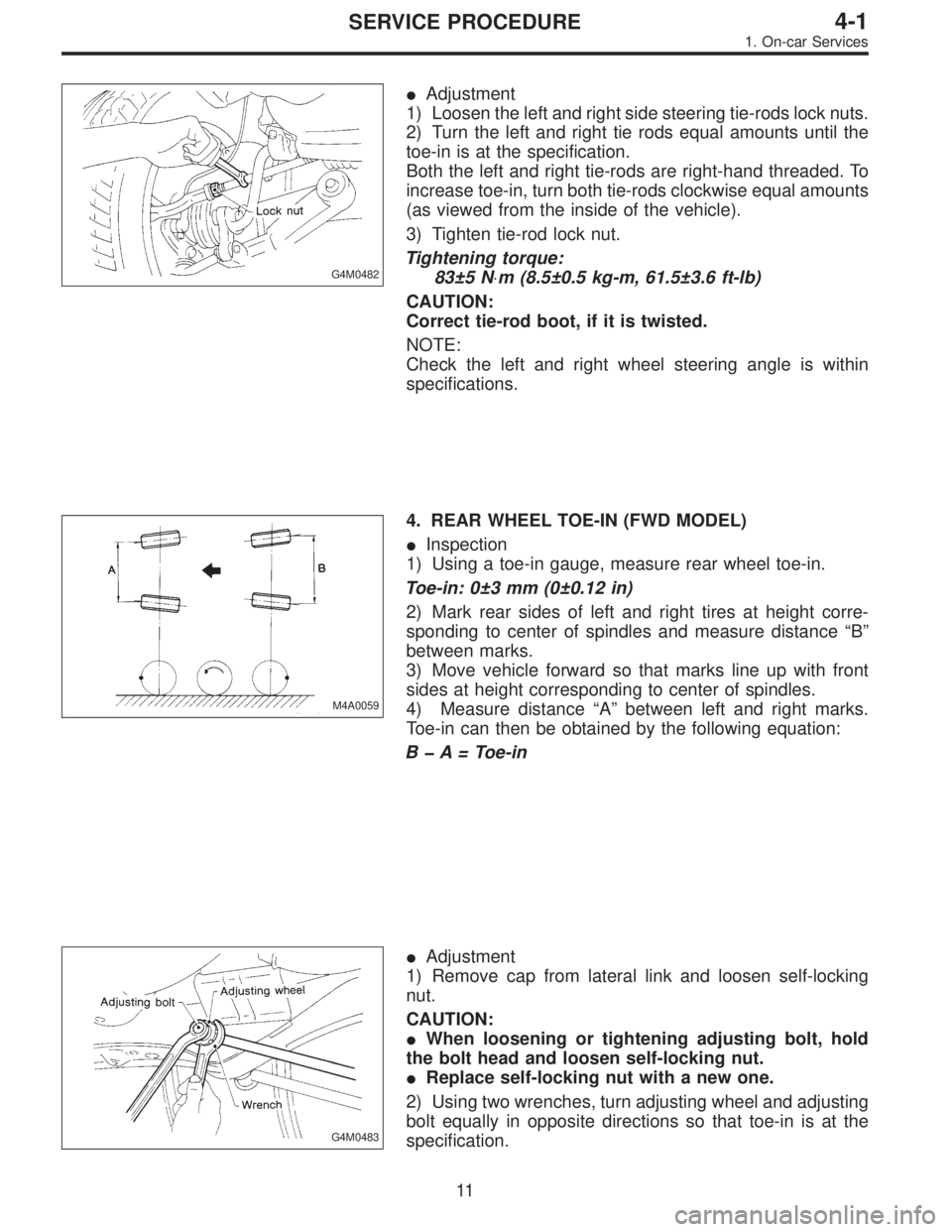
G4M0482
�Adjustment
1) Loosen the left and right side steering tie-rods lock nuts.
2) Turn the left and right tie rods equal amounts until the
toe-in is at the specification.
Both the left and right tie-rods are right-hand threaded. To
increase toe-in, turn both tie-rods clockwise equal amounts
(as viewed from the inside of the vehicle).
3) Tighten tie-rod lock nut.
Tightening torque:
83±5 N⋅m (8.5±0.5 kg-m, 61.5±3.6 ft-lb)
CAUTION:
Correct tie-rod boot, if it is twisted.
NOTE:
Check the left and right wheel steering angle is within
specifications.
M4A0059
4. REAR WHEEL TOE-IN (FWD MODEL)
�Inspection
1) Using a toe-in gauge, measure rear wheel toe-in.
Toe-in: 0±3 mm (0±0.12 in)
2) Mark rear sides of left and right tires at height corre-
sponding to center of spindles and measure distance“B”
between marks.
3) Move vehicle forward so that marks line up with front
sides at height corresponding to center of spindles.
4) Measure distance“A”between left and right marks.
Toe-in can then be obtained by the following equation:
B�A = Toe-in
G4M0483
�Adjustment
1) Remove cap from lateral link and loosen self-locking
nut.
CAUTION:
�When loosening or tightening adjusting bolt, hold
the bolt head and loosen self-locking nut.
�Replace self-locking nut with a new one.
2) Using two wrenches, turn adjusting wheel and adjusting
bolt equally in opposite directions so that toe-in is at the
specification.
11
4-1SERVICE PROCEDURE
1. On-car Services