Page 435 of 3342
Lower level
3.5�(3.7 US qt, 3.1 Imp qt)
G2M0088
3. Oil Pressure Switch
A: REMOVAL
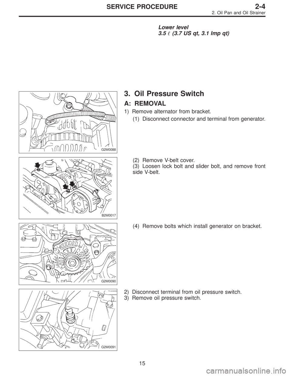
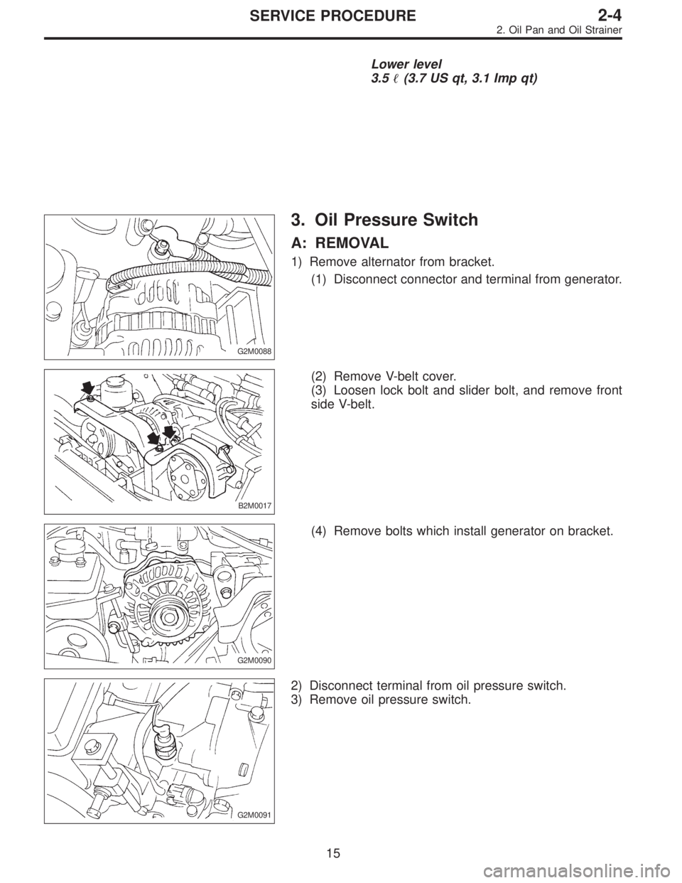
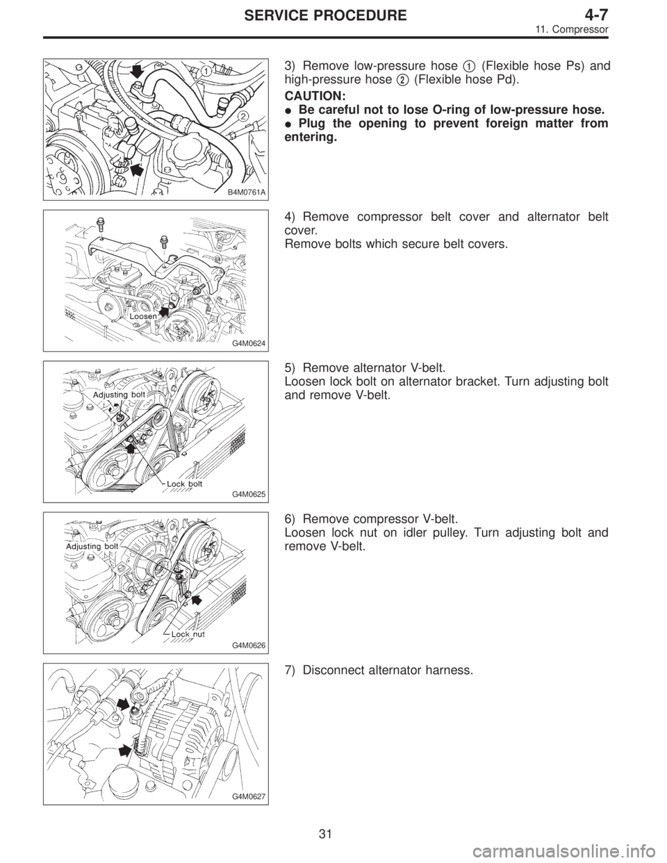
1) Remove alternator from bracket.
(1) Disconnect connector and terminal from generator.
B2M0017
(2) Remove V-belt cover.
(3) Loosen lock bolt and slider bolt, and remove front
side V-belt.
G2M0090
(4) Remove bolts which install generator on bracket.
G2M0091
2) Disconnect terminal from oil pressure switch.
3) Remove oil pressure switch.
15
2-4SERVICE PROCEDURE
2. Oil Pan and Oil Strainer
Page 436 of 3342
Lower level
3.5�(3.7 US qt, 3.1 Imp qt)
G2M0088
3. Oil Pressure Switch
A: REMOVAL
1) Remove alternator from bracket.
(1) Disconnect connector and terminal from generator.
B2M0017
(2) Remove V-belt cover.
(3) Loosen lock bolt and slider bolt, and remove front
side V-belt.
G2M0090
(4) Remove bolts which install generator on bracket.
G2M0091
2) Disconnect terminal from oil pressure switch.
3) Remove oil pressure switch.
15
2-4SERVICE PROCEDURE
2. Oil Pan and Oil Strainer
Page 1254 of 3342
B4M1160
8. Oil Pump (Power Steering System)
A: REMOVAL
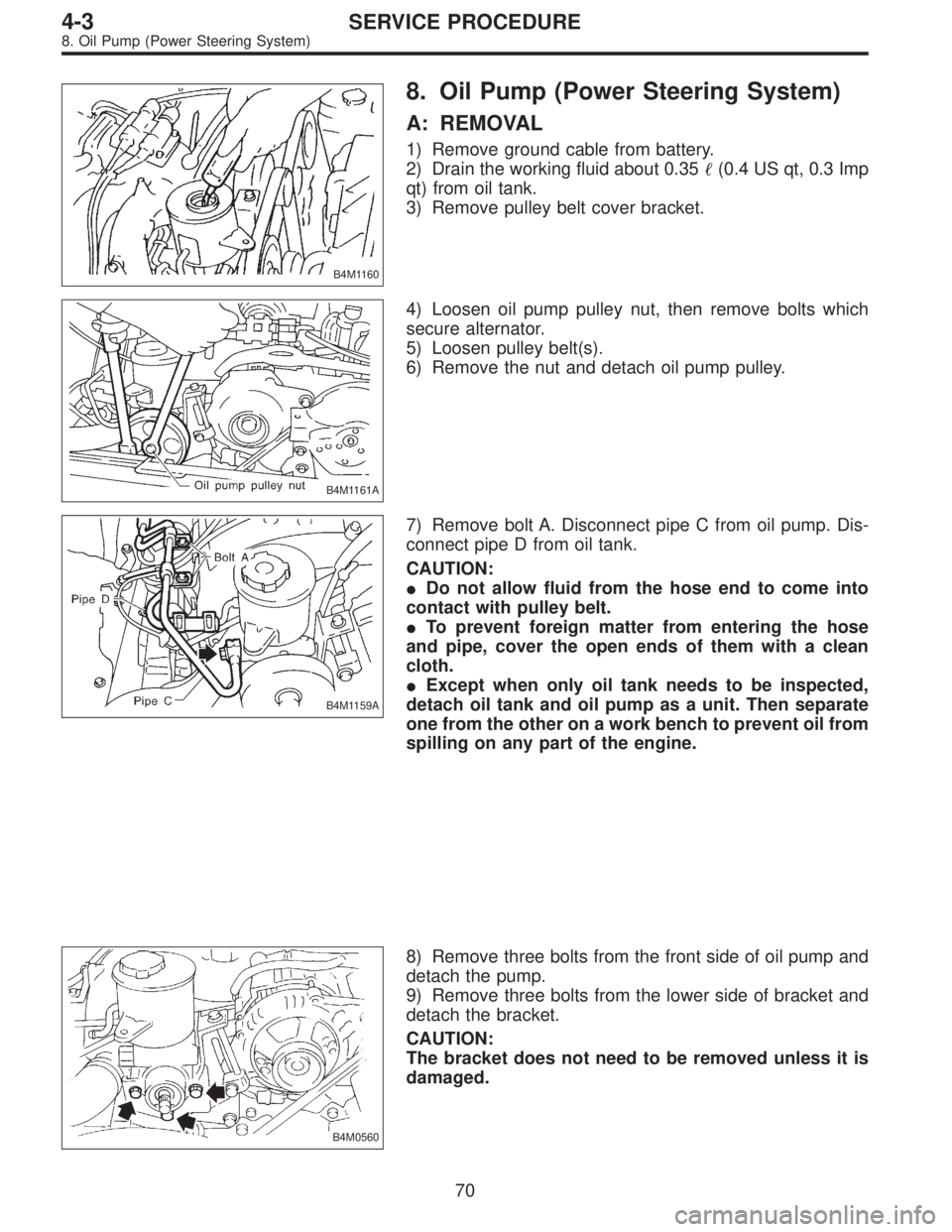
1) Remove ground cable from battery.
2) Drain the working fluid about 0.35�(0.4 US qt, 0.3 Imp
qt) from oil tank.
3) Remove pulley belt cover bracket.
B4M1161A
4) Loosen oil pump pulley nut, then remove bolts which
secure alternator.
5) Loosen pulley belt(s).
6) Remove the nut and detach oil pump pulley.
B4M1159A
7) Remove bolt A. Disconnect pipe C from oil pump. Dis-
connect pipe D from oil tank.
CAUTION:
�Do not allow fluid from the hose end to come into
contact with pulley belt.
�To prevent foreign matter from entering the hose
and pipe, cover the open ends of them with a clean
cloth.
�Except when only oil tank needs to be inspected,
detach oil tank and oil pump as a unit. Then separate
one from the other on a work bench to prevent oil from
spilling on any part of the engine.
B4M0560
8) Remove three bolts from the front side of oil pump and
detach the pump.
9) Remove three bolts from the lower side of bracket and
detach the bracket.
CAUTION:
The bracket does not need to be removed unless it is
damaged.
70
4-3SERVICE PROCEDURE
8. Oil Pump (Power Steering System)
Page 1485 of 3342
B4M0761A
3) Remove low-pressure hose�1(Flexible hose Ps) and
high-pressure hose�
2(Flexible hose Pd).
CAUTION:
�Be careful not to lose O-ring of low-pressure hose.
�Plug the opening to prevent foreign matter from
entering.
G4M0624
4) Remove compressor belt cover and alternator belt
cover.
Remove bolts which secure belt covers.
G4M0625
5) Remove alternator V-belt.
Loosen lock bolt on alternator bracket. Turn adjusting bolt
and remove V-belt.
G4M0626
6) Remove compressor V-belt.
Loosen lock nut on idler pulley. Turn adjusting bolt and
remove V-belt.
G4M0627
7) Disconnect alternator harness.
31
4-7SERVICE PROCEDURE
11. Compressor
Page 1486 of 3342
G4M0628
8) Disconnect compressor harness.
Disconnect compressor harness from body harness.
9) Lower bracket.
Remove bolts which secure lower compressor bracket.
G4M0629
10) Remove compressor.
Remove bolt which secure compressor. Remove compres-
sor from bracket.
G4M0630
C: INSTALLATION
1) Install compressor.
Install compressor on bracket.
2) Connect compressor harness.
3) Connect alternator harness.
4) Install compressor V-belt (Rear).
After adjusting belt tension, tighten tension pulley lock nut
securely.
G4M0632
5) Install alternator V-belt.
After adjusting V-belt tension, tighten alternator bracket
lock bolt securely.
6) Check drive belt tension and adjust it if necessary by
changing alternator position and/or idler pulley position.
32
4-7SERVICE PROCEDURE
11. Compressor
Page 1487 of 3342
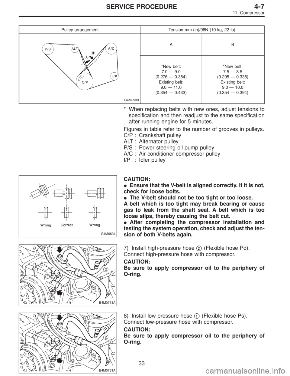
Pulley arrangement Tension mm (in)/98N (10 kg, 22 lb)
G4M0939
AB
*New belt:
7.0—9.0
(0.276—0.354)
Existing belt:
9.0—11.0
(0.354—0.433)*New belt:
7.5—8.5
(0.295—0.335)
Existing belt:
9.0—10.0
(0.354—0.394)
* When replacing belts with new ones, adjust tensions to
specification and then readjust to the same specification
after running engine for 5 minutes.
Figures in table refer to the number of grooves in pulleys.
C/P : Crankshaft pulley
ALT : Alternator pulley
P/S : Power steering oil pump pulley
A/C : Air conditioner compressor pulley
I/P : Idler pulley
G4M0634
CAUTION:
�Ensure that the V-belt is aligned correctly. If it is not,
check for loose bolts.
�The V-belt should not be too tight or too loose.
A belt which is too tight may break bearing or cause
gas to leak from the shaft seal. A belt which is too
loose slips, thereby causing the belt cut.
�After completing the compressor installation and
testing the system operation, check and adjust the ten-
sion of both V-belts again.
B4M0761A
7) Install high-pressure hose�2(Flexible hose Pd).
Connect high-pressure hose with compressor.
CAUTION:
Be sure to apply compressor oil to the periphery of
O-ring.
B4M0761A
8) Install low-pressure hose�1(Flexible hose Ps).
Connect low-pressure hose with compressor.
CAUTION:
Be sure to apply compressor oil to the periphery of
O-ring.
33
4-7SERVICE PROCEDURE
11. Compressor