Page 220 of 3342
Connector
Connecting
to
No
.
Pole
Color
Area
No
.
Name
i1
22
Black
C-4
B36
i2
22
G4
B37
i3
22
Brown
C-4
B38
Bulkhead
wiring
harness
i4
20
Blue
C-4
B39
i5
15
Gray
C-4F!B
i6
10
C-4
Remote
control
rearview
mirror
switch
i10
16
Light
gray
B-3
i11
5
Light
blueB-3
Combination
meter
i12
16
Light
gray
B-3
Combination
meter
04
13
B-3
Combination
meter
05
6B-2
Fan
switch
07
16
Black
B-2
Mode
control
panel
08
6B-3
Rear
defogger
switch
09
6
Brown
B-3Cruise
control
main
switch
i20
4
Blue
B-2
B80
Bulkhead
wiring
harness
i22
10
B-2
Hazard
switch
i23
2
Brown
B-2
Glove
box
illumination
light
i24
1
G2
i25
3C-2Front
accessory
power
supply
i26
14
B-2
Radio
i27
2B-2
CD
player
illumination
light
i28
1
Black
C-2
Ground
i29
1
Black
C-2
Ground
(Radio)
i30
4B-2
Rear
window
defogger
timer
'
:
Non-colored
5
.
INSTRUMENT
PANEL
WIRING
HARNESS
AND
GROUND
POINT
9
RHD
model
1
23
AI
B
C
DI
1
2
3
5
Page 221 of 3342
Connector
Connecting
to
ole
Color
Area
No
.
Name
22
Black
C-4
B36
22
C-4
B37
lkh
ii
h
?2
Brown
C-4
B38
ead
w
r
ng
arness
Bu
20
Blue
C-4
B39
15
Gray
C-4
FIB
10
C-4
Remote
control
rearview
mirrorswitch
16
Light
gray
B-3
ii
5
Light
blue
B-3
Comb
nat
on
meter
16
Light
gray
B-3
Combination
meter
13
B-3
Combination
meter
6
B-2
Fan
switch
16
Black
B-2
Mode
control
panel
6
B-3
Rear
defogger
switch
6
Brown
B-3
Cruise
control
main
switch
4
Blue
B-2
B80
Bulkhead
wiring
harness
10
B-2
Hazard
switch
2
Brown
B-2
Glove
box
illumination
light
1
G2
F3
G2
ront
accessory
power
supply
14
8-2
Radio
2B-2
CD
player
illumination
light
1
Black
C-2
Ground
1
Black
G2
Ground
(Radio)
4
B-2
Rear
window
defogger
timer
5
.
INSTRUMENT
PANEL
WIRING
HARNESS
AND
GROUND
POINT
e
RHD
model
1
I
2
I
3
A
B
C
D
1
2
3
4
4
[D805]
B6M0849A
A
B
C
C
5
Page 222 of 3342

Connector
Connecting
to
No
.
Pole
Color
Area
No
.
Name
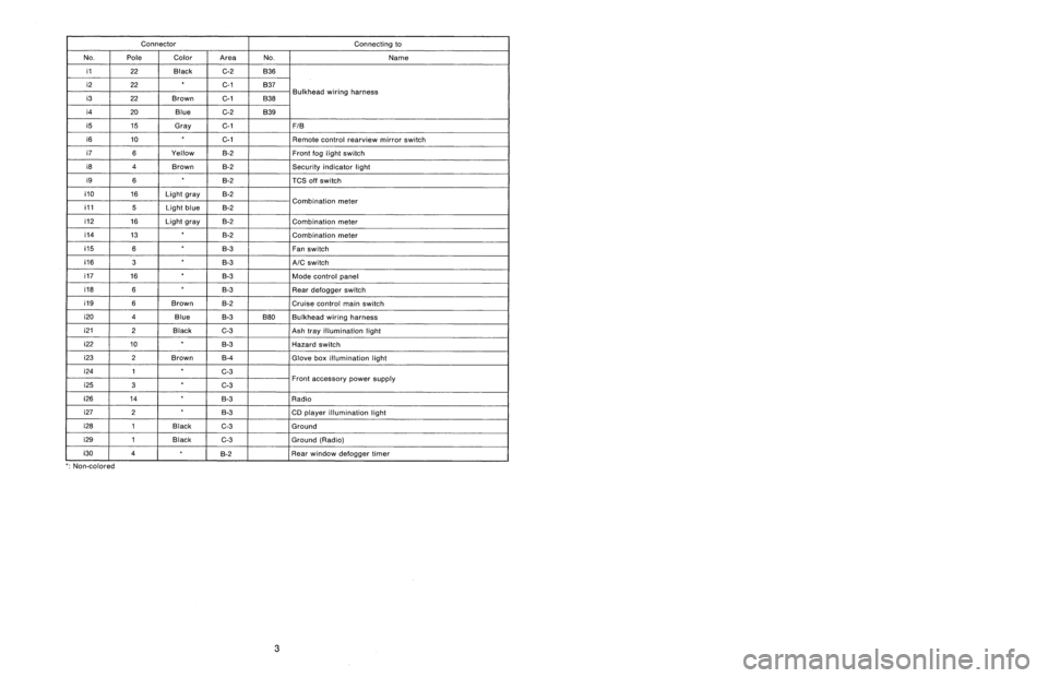
i1
22
Black
C-2
B36
i2
22C-1
B37
i3
22
Brown
C-1
B38
Bulkhead
wiring
harness
i4
20
Blue
C-2
B39
i5
15
Gray
C-1F1B
i6
10
C-1
Remote
control
rearview
mirrorswitch
i7
6
Yellow
B-2Front
fog
light
switch
i8
4
Brown
B-2Security
indicator
light
i9
6B-2
TCS
off
switch
i10
16
Light
gray
B-2
i11
5
Light
blueB-2
Combination
meter
i12
16
Light
gray
B-2
Combination
meter
i14
13
B-2
Combination
meter
05
6
B-3
Fan
switch
06
3
B-3
A/C
switch
07
16
B-3
Mode
control
panel
08
6B-3
Rear
defogger
switch
09
6
Brown
B-2
Cruise
control
main
switch
i20
4
Blue
B-3
B80
Bulkhead
wiring
harness
i212
Black
C-3
Ash
tray
illumination
light
i22
10
B-3
Hazard
switch
i23
2
Brown
B-4
Glove
box
illumination
light
i24
1
C-3
i25
3
C-3Front
accessory
power
supply
i26
14
B-3
Radio
i27
2B-3
CD
player
illumination
light
i28
1
Black
C-3
Ground
i29
1
Black
G3
Ground
(Radio)
i30
4
~
°
g-2
Rear
window
defogger
timer
'
:
Non-colored
8
.
Electrical
Wiring
Harness
and
Ground
Point
5
.
INSTRUMENT
PANEL
WIRING
HARNESS
AND
GROUND
POINT
9
LHD
model
1
23
A
B
CII
C
DI
3
1
23
Page 223 of 3342

Connector
Connecting
to
ole
Color
Area
No
.
Name
?2
Black
G2
B36
?2
C-1
B37
lkh
ii
h
?2
Brown
C-1
B38ead
w
r
ng
arness
Bu
?0
Blue
G-2
B39
15
Gray
C-1FIB
10
C-1
Remote
control
rearview
mirrorswitch
6
Yellow
B-2
Front
fog
light
switch
4
Brown
B-2Security
indicator
light
6B-2
TCS
off
switch
16
Light
gray
B-2
ii
5
Light
blueB-2
Comb
nat
on
meter
16
Light
gray
B-2
Combination
meter
13
~
B-2
Combination
meter
6B-3
Fan
switch
3B-3
A/C
switch
16
B-3
Mode
control
panel
6
B-3
Rear
defogger
switch
6
Brown
8-2Cruise
control
main
switch
4
Blue
B-3B80
Bulkhead
wiring
harness
?
Black
C-3
Ash
trayillumination
light
0
B-3
Hazard
switch
?
Brown
B-4
Glove
box
illumination
light
1
C-3
3
C-3Front
accessory
power
supply
4B-3
Radio
2
B-3
CD
player
illumination
light
I
Black
C-3
Ground
I
Black
C-3
Ground
(Radio)
B-2
~
~
Rear
window
defogger
timer
3
8
.
Electrical
Wiring
Harness
andGround
Point
5
.
INSTRUMENT
PANEL
WIRING
HARNESS
AND
GROUND
POINT
e
LHD
model
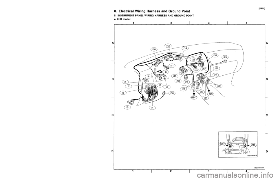
[D805]
1
I
2
I
3
A
B
C
1
2
3
4
4
B6M0848A
A
B
C
Page 1739 of 3342

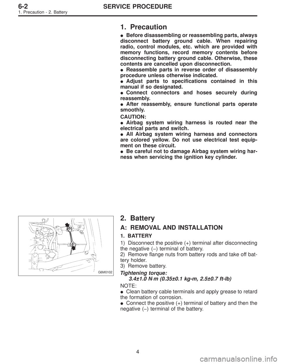
1. Precaution
�Before disassembling or reassembling parts, always
disconnect battery ground cable. When repairing
radio, control modules, etc. which are provided with
memory functions, record memory contents before
disconnecting battery ground cable. Otherwise, these
contents are cancelled upon disconnection.
�Reassemble parts in reverse order of disassembly
procedure unless otherwise indicated.
�Adjust parts to specifications contained in this
manual if so designated.
�Connect connectors and hoses securely during
reassembly.
�After reassembly, ensure functional parts operate
smoothly.
CAUTION:
�Airbag system wiring harness is routed near the
electrical parts and switch.
�All Airbag system wiring harness and connectors
are colored yellow. Do not use electrical test equip-
ment on these circuit.
�Be careful not to damage Airbag system wiring har-
ness when servicing the ignition key cylinder.
G6M0102
2. Battery
A: REMOVAL AND INSTALLATION
1. BATTERY
1) Disconnect the positive (+) terminal after disconnecting
the negative (�) terminal of battery.
2) Remove flange nuts from battery rods and take off bat-
tery holder.
3) Remove battery.
Tightening torque:
3.4±1.0 N⋅m (0.35±0.1 kg-m, 2.5±0.7 ft-lb)
NOTE:
�Clean battery cable terminals and apply grease to retard
the formation of corrosion.
�Connect the positive (+) terminal of battery and then the
negative (�) terminal of the battery.
4
6-2SERVICE PROCEDURE
1. Precaution - 2. Battery
Page 1740 of 3342

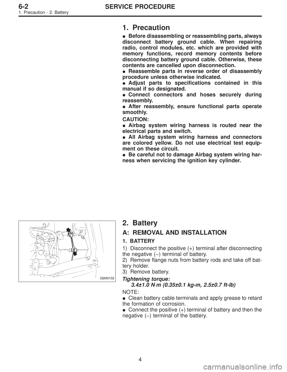
1. Precaution
�Before disassembling or reassembling parts, always
disconnect battery ground cable. When repairing
radio, control modules, etc. which are provided with
memory functions, record memory contents before
disconnecting battery ground cable. Otherwise, these
contents are cancelled upon disconnection.
�Reassemble parts in reverse order of disassembly
procedure unless otherwise indicated.
�Adjust parts to specifications contained in this
manual if so designated.
�Connect connectors and hoses securely during
reassembly.
�After reassembly, ensure functional parts operate
smoothly.
CAUTION:
�Airbag system wiring harness is routed near the
electrical parts and switch.
�All Airbag system wiring harness and connectors
are colored yellow. Do not use electrical test equip-
ment on these circuit.
�Be careful not to damage Airbag system wiring har-
ness when servicing the ignition key cylinder.
G6M0102
2. Battery
A: REMOVAL AND INSTALLATION
1. BATTERY
1) Disconnect the positive (+) terminal after disconnecting
the negative (�) terminal of battery.
2) Remove flange nuts from battery rods and take off bat-
tery holder.
3) Remove battery.
Tightening torque:
3.4±1.0 N⋅m (0.35±0.1 kg-m, 2.5±0.7 ft-lb)
NOTE:
�Clean battery cable terminals and apply grease to retard
the formation of corrosion.
�Connect the positive (+) terminal of battery and then the
negative (�) terminal of the battery.
4
6-2SERVICE PROCEDURE
1. Precaution - 2. Battery
Page 1790 of 3342
B6M0144A
3. SUNROOF RELAY
Check continuity between terminals as indicated in table
below, when battery voltage is applied between terminals
No. 1 and No. 3.
When current flows. Between terminals
No. 2 and No. 4Continuity exists.
When current does not flow. Between terminals
No. 2 and No. 4Continuity does not
exist.
Between terminals
No. 1 and No. 3Continuity exists.
B6M0354
20. Radio, Speaker and Antenna
A: REMOVAL AND INSTALLATION
1. RADIO BODY
1) Remove hand brake cover.
2) Remove console cover.
3) Remove screws which secure center panel. Remove
center panel.
B6M0355
4) Remove fitting screws, and slightly pull radio out of
instrument panel.
5) Disconnect connectors and antenna feeder cord.
B6M0146
2. FRONT SPEAKER
1) Remove gusset speaker from behind the rearview mir-
ror while disconnecting connector.
2) Remove door trim panel.
46
6-2SERVICE PROCEDURE
19. Sunroof - 20. Radio, Speaker and Antenna
Page 1791 of 3342
B6M0144A
3. SUNROOF RELAY
Check continuity between terminals as indicated in table
below, when battery voltage is applied between terminals
No. 1 and No. 3.
When current flows. Between terminals
No. 2 and No. 4Continuity exists.
When current does not flow. Between terminals
No. 2 and No. 4Continuity does not
exist.
Between terminals
No. 1 and No. 3Continuity exists.
B6M0354
20. Radio, Speaker and Antenna
A: REMOVAL AND INSTALLATION
1. RADIO BODY
1) Remove hand brake cover.
2) Remove console cover.
3) Remove screws which secure center panel. Remove
center panel.
B6M0355
4) Remove fitting screws, and slightly pull radio out of
instrument panel.
5) Disconnect connectors and antenna feeder cord.
B6M0146
2. FRONT SPEAKER
1) Remove gusset speaker from behind the rearview mir-
ror while disconnecting connector.
2) Remove door trim panel.
46
6-2SERVICE PROCEDURE
19. Sunroof - 20. Radio, Speaker and Antenna