Page 220 of 3342
Connector
Connecting
to
No
.
Pole
Color
Area
No
.
Name
i1
22
Black
C-4
B36
i2
22
G4
B37
i3
22
Brown
C-4
B38
Bulkhead
wiring
harness
i4
20
Blue
C-4
B39
i5
15
Gray
C-4F!B
i6
10
C-4
Remote
control
rearview
mirror
switch
i10
16
Light
gray
B-3
i11
5
Light
blueB-3
Combination
meter
i12
16
Light
gray
B-3
Combination
meter
04
13
B-3
Combination
meter
05
6B-2
Fan
switch
07
16
Black
B-2
Mode
control
panel
08
6B-3
Rear
defogger
switch
09
6
Brown
B-3Cruise
control
main
switch
i20
4
Blue
B-2
B80
Bulkhead
wiring
harness
i22
10
B-2
Hazard
switch
i23
2
Brown
B-2
Glove
box
illumination
light
i24
1
G2
i25
3C-2Front
accessory
power
supply
i26
14
B-2
Radio
i27
2B-2
CD
player
illumination
light
i28
1
Black
C-2
Ground
i29
1
Black
C-2
Ground
(Radio)
i30
4B-2
Rear
window
defogger
timer
'
:
Non-colored
5
.
INSTRUMENT
PANEL
WIRING
HARNESS
AND
GROUND
POINT
9
RHD
model
1
23
AI
B
C
DI
1
2
3
5
Page 221 of 3342
Connector
Connecting
to
ole
Color
Area
No
.
Name
22
Black
C-4
B36
22
C-4
B37
lkh
ii
h
?2
Brown
C-4
B38
ead
w
r
ng
arness
Bu
20
Blue
C-4
B39
15
Gray
C-4
FIB
10
C-4
Remote
control
rearview
mirrorswitch
16
Light
gray
B-3
ii
5
Light
blue
B-3
Comb
nat
on
meter
16
Light
gray
B-3
Combination
meter
13
B-3
Combination
meter
6
B-2
Fan
switch
16
Black
B-2
Mode
control
panel
6
B-3
Rear
defogger
switch
6
Brown
B-3
Cruise
control
main
switch
4
Blue
B-2
B80
Bulkhead
wiring
harness
10
B-2
Hazard
switch
2
Brown
B-2
Glove
box
illumination
light
1
G2
F3
G2
ront
accessory
power
supply
14
8-2
Radio
2B-2
CD
player
illumination
light
1
Black
C-2
Ground
1
Black
G2
Ground
(Radio)
4
B-2
Rear
window
defogger
timer
5
.
INSTRUMENT
PANEL
WIRING
HARNESS
AND
GROUND
POINT
e
RHD
model
1
I
2
I
3
A
B
C
D
1
2
3
4
4
[D805]
B6M0849A
A
B
C
C
5
Page 222 of 3342

Connector
Connecting
to
No
.
Pole
Color
Area
No
.
Name
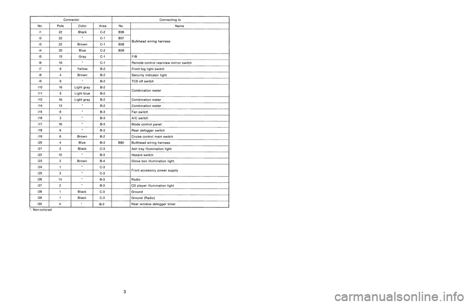
i1
22
Black
C-2
B36
i2
22C-1
B37
i3
22
Brown
C-1
B38
Bulkhead
wiring
harness
i4
20
Blue
C-2
B39
i5
15
Gray
C-1F1B
i6
10
C-1
Remote
control
rearview
mirrorswitch
i7
6
Yellow
B-2Front
fog
light
switch
i8
4
Brown
B-2Security
indicator
light
i9
6B-2
TCS
off
switch
i10
16
Light
gray
B-2
i11
5
Light
blueB-2
Combination
meter
i12
16
Light
gray
B-2
Combination
meter
i14
13
B-2
Combination
meter
05
6
B-3
Fan
switch
06
3
B-3
A/C
switch
07
16
B-3
Mode
control
panel
08
6B-3
Rear
defogger
switch
09
6
Brown
B-2
Cruise
control
main
switch
i20
4
Blue
B-3
B80
Bulkhead
wiring
harness
i212
Black
C-3
Ash
tray
illumination
light
i22
10
B-3
Hazard
switch
i23
2
Brown
B-4
Glove
box
illumination
light
i24
1
C-3
i25
3
C-3Front
accessory
power
supply
i26
14
B-3
Radio
i27
2B-3
CD
player
illumination
light
i28
1
Black
C-3
Ground
i29
1
Black
G3
Ground
(Radio)
i30
4
~
°
g-2
Rear
window
defogger
timer
'
:
Non-colored
8
.
Electrical
Wiring
Harness
and
Ground
Point
5
.
INSTRUMENT
PANEL
WIRING
HARNESS
AND
GROUND
POINT
9
LHD
model
1
23
A
B
CII
C
DI
3
1
23
Page 223 of 3342

Connector
Connecting
to
ole
Color
Area
No
.
Name
?2
Black
G2
B36
?2
C-1
B37
lkh
ii
h
?2
Brown
C-1
B38ead
w
r
ng
arness
Bu
?0
Blue
G-2
B39
15
Gray
C-1FIB
10
C-1
Remote
control
rearview
mirrorswitch
6
Yellow
B-2
Front
fog
light
switch
4
Brown
B-2Security
indicator
light
6B-2
TCS
off
switch
16
Light
gray
B-2
ii
5
Light
blueB-2
Comb
nat
on
meter
16
Light
gray
B-2
Combination
meter
13
~
B-2
Combination
meter
6B-3
Fan
switch
3B-3
A/C
switch
16
B-3
Mode
control
panel
6
B-3
Rear
defogger
switch
6
Brown
8-2Cruise
control
main
switch
4
Blue
B-3B80
Bulkhead
wiring
harness
?
Black
C-3
Ash
trayillumination
light
0
B-3
Hazard
switch
?
Brown
B-4
Glove
box
illumination
light
1
C-3
3
C-3Front
accessory
power
supply
4B-3
Radio
2
B-3
CD
player
illumination
light
I
Black
C-3
Ground
I
Black
C-3
Ground
(Radio)
B-2
~
~
Rear
window
defogger
timer
3
8
.
Electrical
Wiring
Harness
andGround
Point
5
.
INSTRUMENT
PANEL
WIRING
HARNESS
AND
GROUND
POINT
e
LHD
model
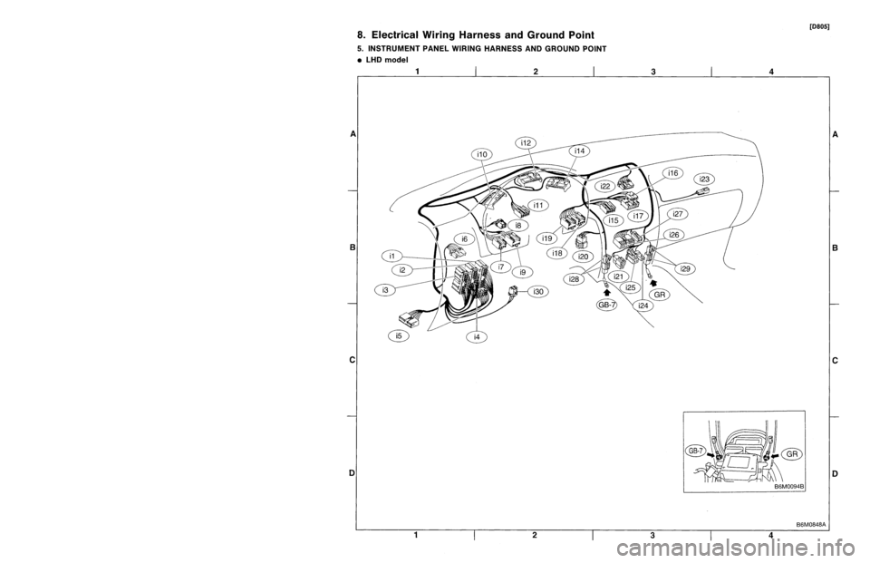
[D805]
1
I
2
I
3
A
B
C
1
2
3
4
4
B6M0848A
A
B
C
Page 1370 of 3342
B4M1031A
2) Secure relay box connector to connector bracket.
CAUTION:
Align connector wit mating receptacle.
3) Using cable clip, secure hydraulic unit harness to relay
box harness.
CAUTION:
Make sure hydraulic unit harness band is secured
beneath cable clip.
4) Connect connector to relay box.
5) Install canister.
6) Install air intake duct.
7) Connect ground cable to battery.
B4M1002
16. ABS Control Module (ABS 5.3 Type)
A: REMOVAL
1. LHD MODEL
1) Turn ignition switch to OFF.
2) Remove front pillar lower trim.
3) Remove glove box.
4) Remove glove box bracket.
B4M1003
5) Remove pocket back panel.
B4M1004
6) Remove bolt from bracket.
88
4-4SERVICE PROCEDURE
15. Hydraulic Unit for ABS System (ABS 5.3 Type) - 16. ABS Control Module (ABS 5.3 Type)
Page 1371 of 3342
B4M1031A
2) Secure relay box connector to connector bracket.
CAUTION:
Align connector wit mating receptacle.
3) Using cable clip, secure hydraulic unit harness to relay
box harness.
CAUTION:
Make sure hydraulic unit harness band is secured
beneath cable clip.
4) Connect connector to relay box.
5) Install canister.
6) Install air intake duct.
7) Connect ground cable to battery.
B4M1002
16. ABS Control Module (ABS 5.3 Type)
A: REMOVAL
1. LHD MODEL
1) Turn ignition switch to OFF.
2) Remove front pillar lower trim.
3) Remove glove box.
4) Remove glove box bracket.
B4M1003
5) Remove pocket back panel.
B4M1004
6) Remove bolt from bracket.
88
4-4SERVICE PROCEDURE
15. Hydraulic Unit for ABS System (ABS 5.3 Type) - 16. ABS Control Module (ABS 5.3 Type)
Page 1448 of 3342
7) Installation is in the reverse order of removal.
Fitted length of heater hose over pipe:
25 — 30 mm (0.98 — 1.18 in)
8) Pour coolant.
B5M0025
3. Blower Motor Assembly
A: REMOVAL AND INSTALLATION
1) Disconnect GND cable from battery.
2) Remove glove box and pocket back panel.
[W1A0].>
3) Disconnect blower motor harness connector.
G4M0555
4) Disconnect aspirator pipe�1.
5) Remove blower motor mounting screw.
6) Remove blower motor assembly.
7) Installation is in the reverse order of removal.
8
4-6SERVICE PROCEDURE
2. Heater Unit - 3. Blower Motor Assembly
Page 1449 of 3342
7) Installation is in the reverse order of removal.
Fitted length of heater hose over pipe:
25 — 30 mm (0.98 — 1.18 in)
8) Pour coolant.
B5M0025
3. Blower Motor Assembly
A: REMOVAL AND INSTALLATION
1) Disconnect GND cable from battery.
2) Remove glove box and pocket back panel.
[W1A0].>
3) Disconnect blower motor harness connector.
G4M0555
4) Disconnect aspirator pipe�1.
5) Remove blower motor mounting screw.
6) Remove blower motor assembly.
7) Installation is in the reverse order of removal.
8
4-6SERVICE PROCEDURE
2. Heater Unit - 3. Blower Motor Assembly