Page 1452 of 3342
B5M0025
5. Intake Door Motor
A: REMOVAL
1) Disconnect GND cable from battery.
2) Remove glove box and pocket back panel.
[W1A0].>
3) Remove heater duct or evaporator. (With A/C model).
G4M0561
4) Remove intake unit from the vehicle.
B4M1428A
5) Remove screws which secure intake door motor to
intake unit.
NOTE:
Ensure that RECIRC switch is set to“ON”.
B4M1429A
11
4-6SERVICE PROCEDURE
5. Intake Door Motor
Page 1491 of 3342
![SUBARU LEGACY 1997 Service Repair Manual G4M0640
13. Receiver Drier
A: REMOVAL AND INSTALLATION
1) Disconnect battery negative terminal.
2) Discharge refrigerant using refrigerant recovery system.
<Ref. to 4-7 [W601].>
3) Disconnect pressure](/manual-img/17/57434/w960_57434-1490.png "SUBARU LEGACY 1997 Service Repair Manual G4M0640
13. Receiver Drier
A: REMOVAL AND INSTALLATION
1) Disconnect battery negative terminal.
2) Discharge refrigerant using refrigerant recovery system.
<Ref. to 4-7 [W601].>
3) Disconnect pressure")
G4M0640
13. Receiver Drier
A: REMOVAL AND INSTALLATION
1) Disconnect battery negative terminal.
2) Discharge refrigerant using refrigerant recovery system.
3) Disconnect pressure switch harness�
1.
4) Disconnect pipes�
2.
5) Remove mounting bolt�
3and remove receiver drier.
CAUTION:
The receiver drier contains a desiccant. Be sure to put
a blind plug in the detached receiver drier to protect it
from moisture.
6) Install the receiver drier in the reverse order of removal.
7) Charge refrigerant.
G4M0641
14. Evaporator Unit
A: REMOVAL AND INSTALLATION
1) Disconnect battery negative terminal.
2) Discharge refrigerant using refrigerant recovery system.
3) Disconnect discharge pipe, suction pipe and grommets.
B5M0025
4) Remove glove box and pocket back panel.
[W1A0].>
G4M0642
5) Disconnect the harness connector from evaporator.
6) Disconnect drain hose.
7) Remove evaporator mounting bolt and nut.
8) Install the evaporator in the reverse order of removal.
9) Charge refrigerant.
36
4-7SERVICE PROCEDURE
13. Receiver Drier - 14. Evaporator Unit
Page 1492 of 3342
![SUBARU LEGACY 1997 Service Repair Manual G4M0640
13. Receiver Drier
A: REMOVAL AND INSTALLATION
1) Disconnect battery negative terminal.
2) Discharge refrigerant using refrigerant recovery system.
<Ref. to 4-7 [W601].>
3) Disconnect pressure](/manual-img/17/57434/w960_57434-1491.png "SUBARU LEGACY 1997 Service Repair Manual G4M0640
13. Receiver Drier
A: REMOVAL AND INSTALLATION
1) Disconnect battery negative terminal.
2) Discharge refrigerant using refrigerant recovery system.
<Ref. to 4-7 [W601].>
3) Disconnect pressure")
G4M0640
13. Receiver Drier
A: REMOVAL AND INSTALLATION
1) Disconnect battery negative terminal.
2) Discharge refrigerant using refrigerant recovery system.
3) Disconnect pressure switch harness�
1.
4) Disconnect pipes�
2.
5) Remove mounting bolt�
3and remove receiver drier.
CAUTION:
The receiver drier contains a desiccant. Be sure to put
a blind plug in the detached receiver drier to protect it
from moisture.
6) Install the receiver drier in the reverse order of removal.
7) Charge refrigerant.
G4M0641
14. Evaporator Unit
A: REMOVAL AND INSTALLATION
1) Disconnect battery negative terminal.
2) Discharge refrigerant using refrigerant recovery system.
3) Disconnect discharge pipe, suction pipe and grommets.
B5M0025
4) Remove glove box and pocket back panel.
[W1A0].>
G4M0642
5) Disconnect the harness connector from evaporator.
6) Disconnect drain hose.
7) Remove evaporator mounting bolt and nut.
8) Install the evaporator in the reverse order of removal.
9) Charge refrigerant.
36
4-7SERVICE PROCEDURE
13. Receiver Drier - 14. Evaporator Unit
Page 1648 of 3342
1. Instrument Panel
Airbag system wiring harness is routed near combination
meter.
CAUTION:
�All Airbag system wiring harness and connectors
are colored yellow. Do not use electrical test equip-
ment on these circuits.
�Be careful not to damage Airbag system wiring har-
ness when servicing the combination meter.
B5M0022A
A: REMOVAL
1) Disconnect GND cable from battery.
2) Remove shift knob (MT model).
3) Remove console cover�
1and front cover�2.
B5M0023
4) Remove console box.
B5M0024A
5) Remove lower cover and then disconnect connector.
B5M0025
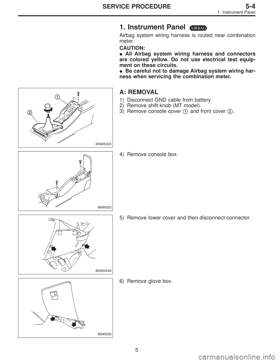
6) Remove glove box.
5
5-4SERVICE PROCEDURE
1. Instrument Panel
Page 1737 of 3342
, 100 minutes (AT)
Cold cranking ampere 430 amperes (MT), 490 amperes (AT)
Fuse10 A, 15 A, 20 A
Combination
meterSpeedometer")
1. Body Electrical
A: SPECIFICATIONS
BatteryReserve capacity 82 minutes (MT), 100 minutes (AT)
Cold cranking ampere 430 amperes (MT), 490 amperes (AT)
Fuse10 A, 15 A, 20 A
Combination
meterSpeedometer Electric pulse type
Tachometer Electric impulse type
Water temperature gauge Thermistor cross coil type
Fuel gauge Resistance cross coil type
Charge indicator light 12 V—1.4 W
Brake fluid level warning/parking brake indicator light 12 V—1.4 W
AT oil temperature warning light (AWD only) 12 V—1.4 W
ABS warning light 12 V—1.4 W
CHECK ENGINE warning light
(Malfunction indicator lamp)12 V—1.4 W
Oil pressure warning light 12 V—1.4 W
AIRBAG system warning light 12 V—1.4 W
Low fuel warning light 12 V—3W
FWD indicator light 12 V—1.4 W
TCS warning light 12 V—1.4 W
TCS indicator light 12 V—1.4 W
Turn signal indicator light 12 V—1.4 W (2 pieces)
Seat belt warning light 12 V—1.4 W
Door open warning light 12 V—1.4 W (5 pieces)
Headlight beam indicator light 12 V—1.4 W
Meter illumination light12 V—3 W (2 pieces)
12 V—3.4 W (4 pieces)
Headlight 12 V—60/55 W (Halogen)
Front clearance light 12 V—5W
Turn signal lightFront 12 V—21 W
Rear 12 V—21 W
Tail/Stop light 12 V—5/21 W
Back-up light 12 V—21 W
High-mount stop light12 V—18 W (SEDAN), 12 V—13 W
(WAGON)
License plate light 12 V—5W
Room light 12 V—8W
Trunk room light (SEDAN) 12 V—5W
Luggage room light (WAGON) 12 V—5W
Spot light 12 V—8 W (2 pieces)
Glove box light 12 V—3.4 W
Ash tray illumination light 12 V—1.7 W
Selector lever illumination light (AT model) 12 V—1.7 W
2
6-2SPECIFICATIONS
1. Body Electrical
Page 3311 of 3342

Connector Connecting to
No. Pole Color Area No. Name
i1 22 Black C-2 B36
Bulkhead wiring harness i2 22 * C-1 B37
i3 22 Brown C-1 B38
i4 20 Blue C-2 B39
i5 15 Gray C-1 F/B
i6 10 * C-1 Remote control rearview mirror switch
i7 6 Yellow B-2 Front fog light switch
i8 4 Brown B-2 Security indicator light
i9 6 * B-2 TCS off switch
i10 16 Light gray B-2
Combination meter
i11 5 Light blue B-2
i12 16 Light gray B-2 Combination meter
i14 13 * B-2 Combination meter
i15 6 * B-3 Fan switch
i16 3 * B-3 A/C switch
i17 16 * B-3 Mode control panel
i18 6 * B-3 Rear defogger switch
i19 6 Brown B-2 Cruise control main switch
i20 4 Blue B-3 B80 Bulkhead wiring harness
i21 2 Black C-3 Ash tray illumination light
i22 10 * B-3 Hazard switch
i23 2 Brown B-4 Glove box illumination light
i24 1 * C-3
Front accessory power supply
i25 3 * C-3
i26 14 * B-3 Radio
i27 2 * B-3 CD player illumination light
i28 1 Black C-3 Ground
i29 1 Black C-3 Ground (Radio)
i30 4 * B-2 Rear window defogger timer
*: Non-colored
132
6-3WIRING DIAGRAM
8. Electrical Wiring Harness and Ground Point
Page 3313 of 3342
Connector Connecting to
No. Pole Color Area No. Name
i1 22 Black C-4 B36
Bulkhead wiring harness i2 22 * C-4 B37
i3 22 Brown C-4 B38
i4 20 Blue C-4 B39
i5 15 Gray C-4 F/B
i6 10 * C-4 Remote control rearview mirror switch
i10 16 Light gray B-3
Combination meter
i11 5 Light blue B-3
i12 16 Light gray B-3 Combination meter
i14 13 * B-3 Combination meter
i15 6 * B-2 Fan switch
i17 16 Black B-2 Mode control panel
i18 6 * B-3 Rear defogger switch
i19 6 Brown B-3 Cruise control main switch
i20 4 Blue B-2 B80 Bulkhead wiring harness
i22 10 * B-2 Hazard switch
i23 2 Brown B-2 Glove box illumination light
i24 1 * C-2
Front accessory power supply
i25 3 * C-2
i26 14 * B-2 Radio
i27 2 * B-2 CD player illumination light
i28 1 Black C-2 Ground
i29 1 Black C-2 Ground (Radio)
i30 4 * B-2 Rear window defogger timer
*: Non-colored
134
6-3WIRING DIAGRAM
8. Electrical Wiring Harness and Ground Point
![SUBARU LEGACY 1997 Service Repair Manual B5M0025
5. Intake Door Motor
A: REMOVAL
1) Disconnect GND cable from battery.
2) Remove glove box and pocket back panel. <Ref. to 5-4
[W1A0].>
3) Remove heater duct or evaporator. (With A/C model).
<R](/manual-img/17/57434/w960_57434-1451.png "SUBARU LEGACY 1997 Service Repair Manual B5M0025
5. Intake Door Motor
A: REMOVAL
1) Disconnect GND cable from battery.
2) Remove glove box and pocket back panel. <Ref. to 5-4
[W1A0].>
3) Remove heater duct or evaporator. (With A/C model).
<R")