Page 241 of 3342
G6M0095
11. Vent Control Solenoid Valve (2200
cc AWD Model)
A: REMOVAL
1) Disconnect battery ground cable.
B2M0964
2) Lift-up the vehicle.
3) Remove canister.
4) Disconnect two hoses from air filter.
5) Disconnect connector from vent control solenoid valve.
H2M1469
6) Remove one bolt fixing bracket on the body.
B2M0965A
7) Remove two vacuum hoses from vent control solenoid
valve.
B2M0966
8) Remove one bolt fixing vent control solenoid valve on
bracket.
9) Remove vent control solenoid valve.
13
2-1SERVICE PROCEDURE
11. Vent Control Solenoid Valve (2200 cc AWD Model)
Page 242 of 3342
B2M0966
B: INSTALLATION
1) Install the bolt fixing vent control solenoid valve on
bracket.
B2M0965A
2) Install two vacuum hoses to vent control solenoid valve.
H2M1469
3) Install the bolt fixing bracket on the body.
Tightening torque:
25±7 N⋅m (2.5±0.7 kg-m, 18.1±5.1 ft-lb)
B2M0964
4) Connect connector to vent control solenoid valve.
5) Connect two hoses to air filter.
6) Install canister.
7) Let down the vehicle.
G6M0095
8) Connect battery ground cable.
14
2-1SERVICE PROCEDURE
11. Vent Control Solenoid Valve (2200 cc AWD Model)
Page 244 of 3342
 Remove two screws fixing bracket on fuel pump assem-
bly.
H2M1461A
8) Remove one screw fixing fuel level sensor on bracket.
9) Remove fuel level sensor from fuel pump assembly.
B2M0955A
B:")
H2M1460
7) Remove two screws fixing bracket on fuel pump assem-
bly.
H2M1461A
8) Remove one screw fixing fuel level sensor on bracket.
9) Remove fuel level sensor from fuel pump assembly.
B2M0955A
B: INSTALLATION
CAUTION:
Leave fuel filler cap open when tightening nuts, to pre-
vent fuel from flowing out through fuel delivery and
return pipes. Close fuel filler cap after tightening nuts.
Installation is in the reverse order of removal. Do the fol-
lowing:
(1) Always use new gaskets.
(2) Ensure sealing portion is free from fuel or foreign
particles before installation.
(3) Tighten nuts in numerical sequence shown in Fig-
ure to specified torque.
Tightening torque:
4.4±1.5 N⋅m (0.45±0.15 kg-m, 3.3±1.1 ft-lb)
B2M0968
13. Air Filter (2200 cc AWD Model)
A: REMOVAL AND INSTALLATION
1) Remove canister.
2) Remove two hoses from air filter.
3) Remove flange nut from bracket.
4) Installation is in the reverse order of removal.
16
2-1SERVICE PROCEDURE
12. Fuel Level Sensor (2200 cc AWD Model) - 13. Air Filter (2200 cc AWD Model)
Page 245 of 3342
 Remove two screws fixing bracket on fuel pump assem-
bly.
H2M1461A
8) Remove one screw fixing fuel level sensor on bracket.
9) Remove fuel level sensor from fuel pump assembly.
B2M0955A
B:")
H2M1460
7) Remove two screws fixing bracket on fuel pump assem-
bly.
H2M1461A
8) Remove one screw fixing fuel level sensor on bracket.
9) Remove fuel level sensor from fuel pump assembly.
B2M0955A
B: INSTALLATION
CAUTION:
Leave fuel filler cap open when tightening nuts, to pre-
vent fuel from flowing out through fuel delivery and
return pipes. Close fuel filler cap after tightening nuts.
Installation is in the reverse order of removal. Do the fol-
lowing:
(1) Always use new gaskets.
(2) Ensure sealing portion is free from fuel or foreign
particles before installation.
(3) Tighten nuts in numerical sequence shown in Fig-
ure to specified torque.
Tightening torque:
4.4±1.5 N⋅m (0.45±0.15 kg-m, 3.3±1.1 ft-lb)
B2M0968
13. Air Filter (2200 cc AWD Model)
A: REMOVAL AND INSTALLATION
1) Remove canister.
2) Remove two hoses from air filter.
3) Remove flange nut from bracket.
4) Installation is in the reverse order of removal.
16
2-1SERVICE PROCEDURE
12. Fuel Level Sensor (2200 cc AWD Model) - 13. Air Filter (2200 cc AWD Model)
Page 438 of 3342
 O")
1. Engine Lubrication System
Before troubleshooting, make sure that the engine oil level
is correct and no oil leakage exists.
Trouble Possible cause Corrective action
1. Warning light remains
on.1) Oil pressure switch
failureCracked diaphragm or oil leakage within switch Replace.
Broken spring or seized contacts Replace.
2) Low oil pressureClogged oil filter Replace.
Malfunction of oil by-pass valve of oil filter Clean or replace.
Malfunction of oil relief valve of oil pump Clean or replace.
Clogged oil passage Clean.
Excessive tip clearance and side clearance of oil
pump rotor and gearReplace.
Clogged oil strainer or broken pipe Clean or replace.
3) No oil pressureInsufficient engine oil Replenish.
Broken pipe of oil strainer Replace.
Stuck oil pump rotor Replace.
2. Warning light does not
go on.1) Burn-out bulb Replace.
2) Poor contact of switch contact points Replace.
3) Disconnection of wiring Repair.
3. Warning light flickers
momentarily.1) Poor contact at terminals Repair.
2) Defective wiring harness Repair.
3) Low oil pressureCheck for the same pos-
sible causes as listed in
1.—2)
17
2-4DIAGNOSTICS
1. Engine Lubrication System
Page 527 of 3342
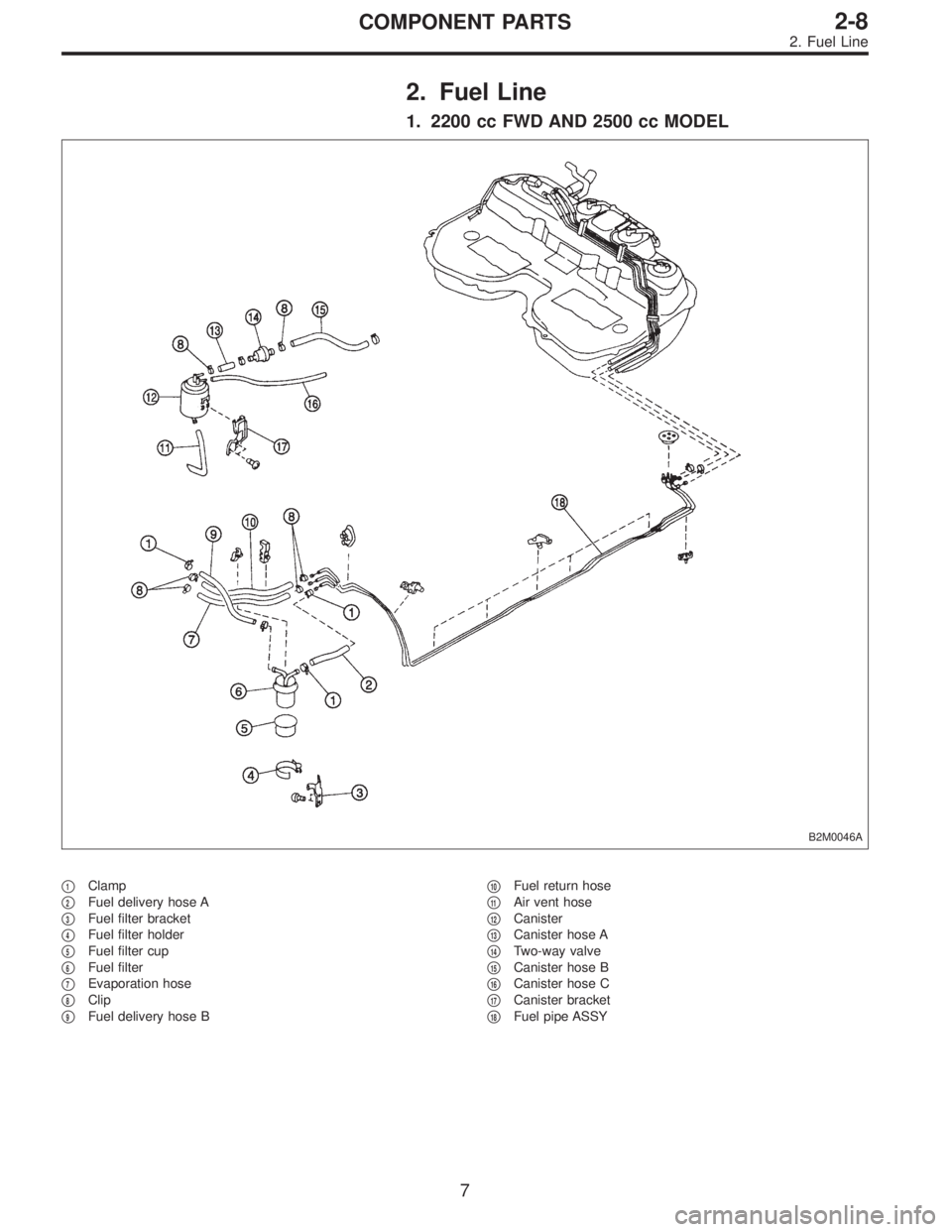
2. Fuel Line
1. 2200 cc FWD AND 2500 cc MODEL
B2M0046A
�1Clamp
�
2Fuel delivery hose A
�
3Fuel filter bracket
�
4Fuel filter holder
�
5Fuel filter cup
�
6Fuel filter
�
7Evaporation hose
�
8Clip
�
9Fuel delivery hose B�
10Fuel return hose
�
11Air vent hose
�
12Canister
�
13Canister hose A
�
14Two-way valve
�
15Canister hose B
�
16Canister hose C
�
17Canister bracket
�
18Fuel pipe ASSY
7
2-8COMPONENT PARTS
2. Fuel Line
Page 529 of 3342

�1Clamp
�
2Fuel delivery hose A
�
3Fuel filter bracket
�
4Fuel filter holder
�
5Fuel filter cup
�
6Fuel filter
�
7Evaporation hose
�
8Clip
�
9Fuel delivery hose B
�
10Fuel return hose
�
11Roll over valve
�
12Roll over valve bracket
�
13Evaporation hose H
�
14Evaporation hose I
�
15Evaporation pipe B
�
16Canister hose A
�
17Canister hose B
�
18Canister holder
�
19Canister upper bracket
�
20Cushion rubber
�
21Canister lower bracket
�
22Canister
�
23Fuel pipe ASSY
�
24Fuel filler valve
�
25Fuel filler pipe
�
26Packing�
27Ring A
�
28Ring B
�
29Fuel filler cap
�
30Fuel filler pipe protector
�
31Fuel tank pressure sensor
�
32Fuel tank pressure sensor hose A
�
33Fuel tank pressure sensor bracket
�
34Grommet
�
35Fuel tank pressure sensor hose B
�
36Air ventilator hose A
�
37Air ventilator pipe A
�
38Air ventilator hose B
�
39Air ventilator pipe B
�
40Air ventilator pipe protector
�
41Vent control solenoid valve
�
42Vent control solenoid valve hose
�
43Air filter hose A
�
44Air filter hose B
�
45Air filter
�
46Tapping screw
Tightening torque: N⋅m (kg-m, ft-lb)
T1: 23±7 (2.3±0.7, 17±5.1)
T2: 25±7 (2.5±0.7, 18±5.1)
9
2-8COMPONENT PARTS
2. Fuel Line
Page 540 of 3342
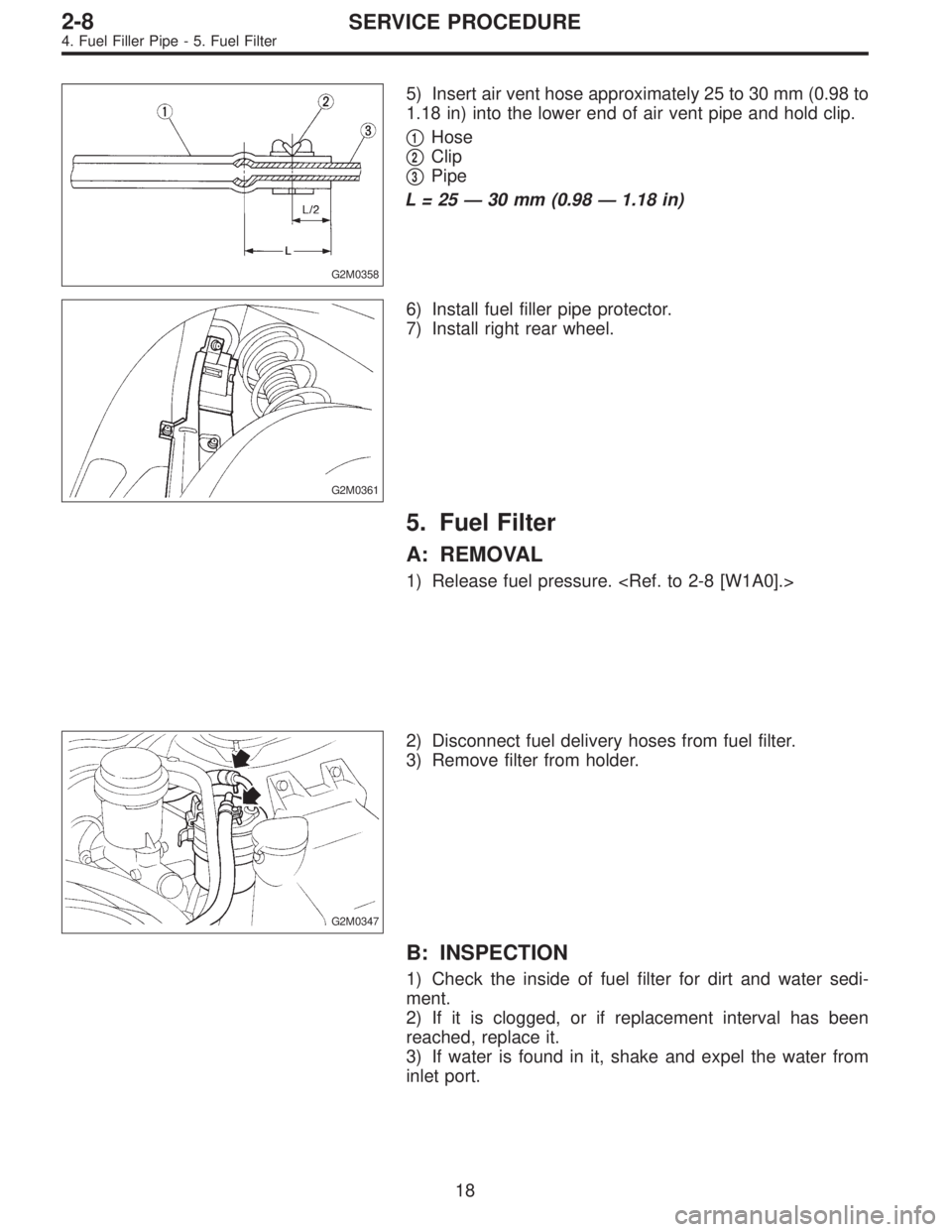
G2M0358
5) Insert air vent hose approximately 25 to 30 mm (0.98 to
1.18 in) into the lower end of air vent pipe and hold clip.
�
1Hose
�
2Clip
�
3Pipe
L=25—30 mm (0.98—1.18 in)
G2M0361
6) Install fuel filler pipe protector.
7) Install right rear wheel.
5. Fuel Filter
A: REMOVAL
1) Release fuel pressure.
G2M0347
2) Disconnect fuel delivery hoses from fuel filter.
3) Remove filter from holder.
B: INSPECTION
1) Check the inside of fuel filter for dirt and water sedi-
ment.
2) If it is clogged, or if replacement interval has been
reached, replace it.
3) If water is found in it, shake and expel the water from
inlet port.
18
2-8SERVICE PROCEDURE
4. Fuel Filler Pipe - 5. Fuel Filter
![SUBARU LEGACY 1997 Service Repair Manual G6M0095
11. Vent Control Solenoid Valve (2200
cc AWD Model)
A: REMOVAL
1) Disconnect battery ground cable.
B2M0964
2) Lift-up the vehicle.
3) Remove canister. <Ref. to 2-1 [W3A2].>
4) Disconnect two h](/manual-img/17/57434/w960_57434-240.png "SUBARU LEGACY 1997 Service Repair Manual G6M0095
11. Vent Control Solenoid Valve (2200
cc AWD Model)
A: REMOVAL
1) Disconnect battery ground cable.
B2M0964
2) Lift-up the vehicle.
3) Remove canister. <Ref. to 2-1 [W3A2].>
4) Disconnect two h")
 Install the bolt fixing vent control solenoid valve on
bracket.
B2M0965A
2) Install two vacuum hoses to vent control solenoid valve.
H2M1469
3) Install the bolt fixing brack")