Page 100 of 3342
4-4d
[Taxo1
BRAKES
[ABS
5
.3i
TYPE]
8
.
Diagnostics
Chart
with
Trouble
Code
by
ABS
Warning
Light
X
:
TROUBLE
CODE
54
-
ABNORMAL
STOP
LIGHT
SWITCH
-
DIAGNOSIS
:
Faulty
stop
light
switch
TROUBLE
SYMPTOM
:
e
ABS
does
notoperate
.
WIRING
DIAGRAM
:
Fuse
S8F-3
FL1
.258
No
.
12
F49
F2
8100
°
Stop
light
switch
172E
I
w
m
OV
LL
3~
E
ABS
control
B64
(Without
cruise
control)
module
and
865
(With
cruise
control)
hydraulic
control
unit
B64
865
8100
F49
123456789101112131415
M1
'
21
1
34
~
34
111
1
141
111
1920
16171819
20
2122
2324
25
26
27
1
28
1
29
1
3
013
11
B4M1258
82
Page 191 of 3342
4-4d
[r1oaFa1
BRAKES
[ABS
5
.31
TYPE]
10
.
Diagnostics
Chart
withSelect
Monitor
B4M0972
AF
:
TROUBLE
CODE
54
BLS
-
ABNORMAL
STOP
LIGHT
SWITCH
-
DIAGNOSIS
:
e
Faulty
stop
light
switch
TROUBLE
SYMPTOM
:
9
ABS
does
not
operate
.
WIRING
DIAGRAM
:
f49
F2
8100
ABS
control
module
and
hydraulic
control
unit
Fuse
SBF-3
FL1
.25B
No
.12
Stop
I
fight
switch
w
U
OV
tt
31311
(
E
B64
(Without
cruise
control)
865
(With
cruise
control)
B64
865
8100
F49
123456789101112131415
1
14
617
1
16
1
17
1
18
1
19
1
20
1
21
1
22
L
3
181
9
1
10
1
4
2526
1
2
4
1
1
11121131
14
1
1
51
161
11
1
81
1
91
20
1
q2
7
1281
29
13013
1
1
B4M1258
182
Page 216 of 3342
6-3
[113soa1
WIRING
DIAGRAM
6
.
Wiring
Diagram
6
.
Wiring
Diagram
4
.
ANTI-LOCK
BRAKE
SYSTEM
CombinationStop
light
To
Power
Supply
Routing
meter
switch
FB-5
SBF-6FB-35FB-22FB-30FB-20
ABS
indicator
FUSE
No
.19
SBF
HOLDER
FUSE
No
.18
FUSE
No
.15
FUSE
k12
FUSE
No
.15
c
:
i14
*
:
With
cruise
control
D
T1
+
:
B65
~~'
B64
i1
B37
w
----------------
r----------
--
--
-----------
F73
(Black)
B65
(Black)
F49
B64
12
456789107112131415
1
4
1
16
1
17
1
118
1
1
21
20
1
21
1
22
[
23242526
U7
1
28
1
29
1
30
13
11
1
i14
i2
1
4
M_
8510
1
456
89
1
10
1
111
1
1
21
1
~
111
1
1415161
119202122
BU82-04A
2
ABS
control
module
and
hydraulic
control
module
Page 220 of 3342
Connector
Connecting
to
No
.
Pole
Color
Area
No
.
Name
i1
22
Black
C-4
B36
i2
22
G4
B37
i3
22
Brown
C-4
B38
Bulkhead
wiring
harness
i4
20
Blue
C-4
B39
i5
15
Gray
C-4F!B
i6
10
C-4
Remote
control
rearview
mirror
switch
i10
16
Light
gray
B-3
i11
5
Light
blueB-3
Combination
meter
i12
16
Light
gray
B-3
Combination
meter
04
13
B-3
Combination
meter
05
6B-2
Fan
switch
07
16
Black
B-2
Mode
control
panel
08
6B-3
Rear
defogger
switch
09
6
Brown
B-3Cruise
control
main
switch
i20
4
Blue
B-2
B80
Bulkhead
wiring
harness
i22
10
B-2
Hazard
switch
i23
2
Brown
B-2
Glove
box
illumination
light
i24
1
G2
i25
3C-2Front
accessory
power
supply
i26
14
B-2
Radio
i27
2B-2
CD
player
illumination
light
i28
1
Black
C-2
Ground
i29
1
Black
C-2
Ground
(Radio)
i30
4B-2
Rear
window
defogger
timer
'
:
Non-colored
5
.
INSTRUMENT
PANEL
WIRING
HARNESS
AND
GROUND
POINT
9
RHD
model
1
23
AI
B
C
DI
1
2
3
5
Page 221 of 3342
Connector
Connecting
to
ole
Color
Area
No
.
Name
22
Black
C-4
B36
22
C-4
B37
lkh
ii
h
?2
Brown
C-4
B38
ead
w
r
ng
arness
Bu
20
Blue
C-4
B39
15
Gray
C-4
FIB
10
C-4
Remote
control
rearview
mirrorswitch
16
Light
gray
B-3
ii
5
Light
blue
B-3
Comb
nat
on
meter
16
Light
gray
B-3
Combination
meter
13
B-3
Combination
meter
6
B-2
Fan
switch
16
Black
B-2
Mode
control
panel
6
B-3
Rear
defogger
switch
6
Brown
B-3
Cruise
control
main
switch
4
Blue
B-2
B80
Bulkhead
wiring
harness
10
B-2
Hazard
switch
2
Brown
B-2
Glove
box
illumination
light
1
G2
F3
G2
ront
accessory
power
supply
14
8-2
Radio
2B-2
CD
player
illumination
light
1
Black
C-2
Ground
1
Black
G2
Ground
(Radio)
4
B-2
Rear
window
defogger
timer
5
.
INSTRUMENT
PANEL
WIRING
HARNESS
AND
GROUND
POINT
e
RHD
model
1
I
2
I
3
A
B
C
D
1
2
3
4
4
[D805]
B6M0849A
A
B
C
C
5
Page 222 of 3342

Connector
Connecting
to
No
.
Pole
Color
Area
No
.
Name
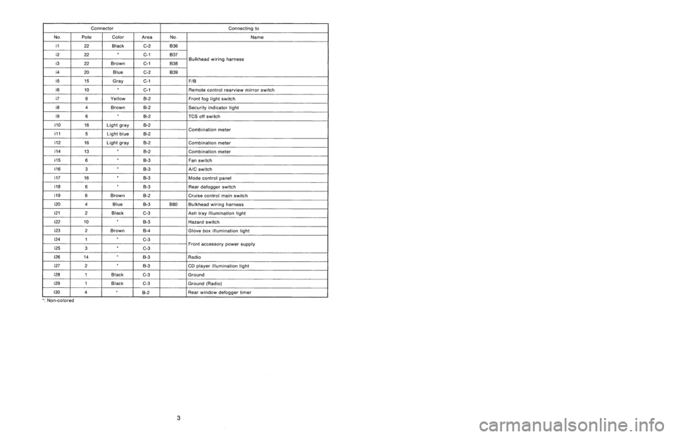
i1
22
Black
C-2
B36
i2
22C-1
B37
i3
22
Brown
C-1
B38
Bulkhead
wiring
harness
i4
20
Blue
C-2
B39
i5
15
Gray
C-1F1B
i6
10
C-1
Remote
control
rearview
mirrorswitch
i7
6
Yellow
B-2Front
fog
light
switch
i8
4
Brown
B-2Security
indicator
light
i9
6B-2
TCS
off
switch
i10
16
Light
gray
B-2
i11
5
Light
blueB-2
Combination
meter
i12
16
Light
gray
B-2
Combination
meter
i14
13
B-2
Combination
meter
05
6
B-3
Fan
switch
06
3
B-3
A/C
switch
07
16
B-3
Mode
control
panel
08
6B-3
Rear
defogger
switch
09
6
Brown
B-2
Cruise
control
main
switch
i20
4
Blue
B-3
B80
Bulkhead
wiring
harness
i212
Black
C-3
Ash
tray
illumination
light
i22
10
B-3
Hazard
switch
i23
2
Brown
B-4
Glove
box
illumination
light
i24
1
C-3
i25
3
C-3Front
accessory
power
supply
i26
14
B-3
Radio
i27
2B-3
CD
player
illumination
light
i28
1
Black
C-3
Ground
i29
1
Black
G3
Ground
(Radio)
i30
4
~
°
g-2
Rear
window
defogger
timer
'
:
Non-colored
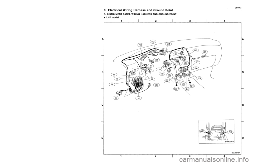
8
.
Electrical
Wiring
Harness
and
Ground
Point
5
.
INSTRUMENT
PANEL
WIRING
HARNESS
AND
GROUND
POINT
9
LHD
model
1
23
A
B
CII
C
DI
3
1
23
Page 223 of 3342

Connector
Connecting
to
ole
Color
Area
No
.
Name
?2
Black
G2
B36
?2
C-1
B37
lkh
ii
h
?2
Brown
C-1
B38ead
w
r
ng
arness
Bu
?0
Blue
G-2
B39
15
Gray
C-1FIB
10
C-1
Remote
control
rearview
mirrorswitch
6
Yellow
B-2
Front
fog
light
switch
4
Brown
B-2Security
indicator
light
6B-2
TCS
off
switch
16
Light
gray
B-2
ii
5
Light
blueB-2
Comb
nat
on
meter
16
Light
gray
B-2
Combination
meter
13
~
B-2
Combination
meter
6B-3
Fan
switch
3B-3
A/C
switch
16
B-3
Mode
control
panel
6
B-3
Rear
defogger
switch
6
Brown
8-2Cruise
control
main
switch
4
Blue
B-3B80
Bulkhead
wiring
harness
?
Black
C-3
Ash
trayillumination
light
0
B-3
Hazard
switch
?
Brown
B-4
Glove
box
illumination
light
1
C-3
3
C-3Front
accessory
power
supply
4B-3
Radio
2
B-3
CD
player
illumination
light
I
Black
C-3
Ground
I
Black
C-3
Ground
(Radio)
B-2
~
~
Rear
window
defogger
timer
3
8
.
Electrical
Wiring
Harness
andGround
Point
5
.
INSTRUMENT
PANEL
WIRING
HARNESS
AND
GROUND
POINT
e
LHD
model
[D805]
1
I
2
I
3
A
B
C
1
2
3
4
4
B6M0848A
A
B
C
Page 477 of 3342
B2M1214A
3. Throttle Body
A: REMOVAL AND INSTALLATION
1) Loosen clamps which connect air intake duct to air
intake chamber and mass air flow sensor.
2) Disconnect blow-by hose from air intake duct.
3) Remove air intake duct.
B2M1218
4) Loosen clamp which connects air intake chamber to
throttle body.
5) Disconnect air hoses, and remove air intake chamber.
G2M0280
6) Disconnect accelerator cable�1.
7) Disconnect cruise control cable�
2. (With cruise control
model)
B2M1247
8) Disconnect connector from throttle position sensor.
B2M1248
9) Disconnect engine coolant hoses from throttle body.
9
2-7SERVICE PROCEDURE
3. Throttle Body