Page 634 of 3342
1. Manual Transmission and
Differential
A: SPECIFICATIONS
ItemModel
2200 cc 2500 cc OUTBACK
Type 5-forward speeds with synchromesh and 1-reverse
Transmission gear ratio1st 3.545
2nd 2.111
3rd 1.448
4th 1.088
5th 0.780 0.871
Reverse 3.416
Front
reduction
gearFinalType of gear Hypoid
Gear ratio 3.900 4.111
Rear
reduction
gearTransferType of gear Helical
Gear ratio 1.000
FinalType of gear Hypoid
Gear ratio 3.900 4.111
Front
differentialType and number of gear Straight bevel gear (Bevel pinion: 2, Bevel gear: 2)
Center
differentialType and number of gear Straight bevel gear (Bevel pinion: 2, Bevel gear: 2 and viscous coupling)
Transmission gear oil GL-5
Transmission oil capacity 3.5�(3.7 US qt, 3.1 Imp qt)
2
3-1SPECIFICATIONS AND SERVICE DATA
1. Manual Transmission and Differential
Page 645 of 3342
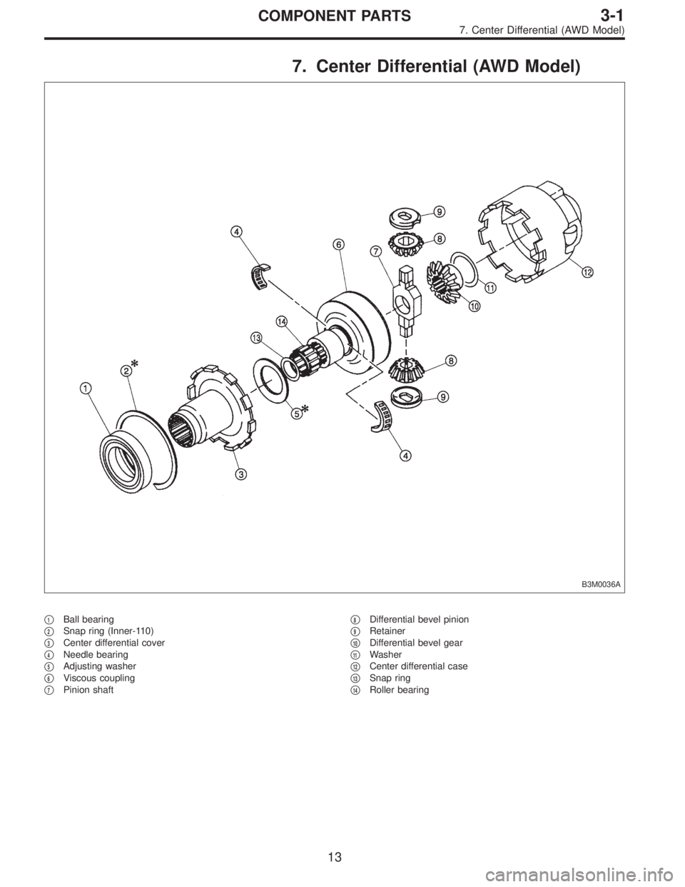
7. Center Differential (AWD Model)
B3M0036A
�1Ball bearing
�
2Snap ring (Inner-110)
�
3Center differential cover
�
4Needle bearing
�
5Adjusting washer
�
6Viscous coupling
�
7Pinion shaft�
8Differential bevel pinion
�
9Retainer
�
10Differential bevel gear
�
11Washer
�
12Center differential case
�
13Snap ring
�
14Roller bearing
13
3-1COMPONENT PARTS
7. Center Differential (AWD Model)
Page 700 of 3342
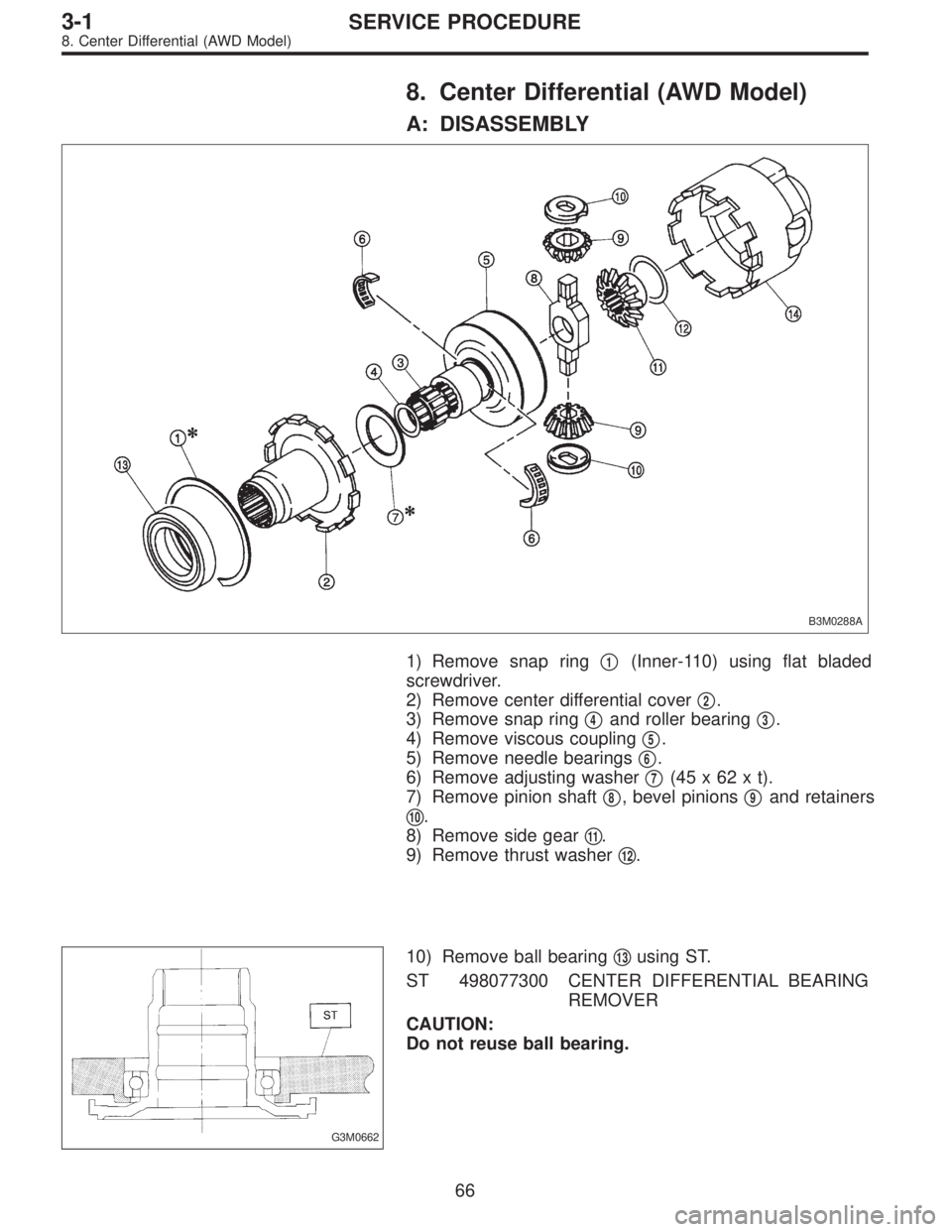
8. Center Differential (AWD Model)
A: DISASSEMBLY
B3M0288A
1) Remove snap ring�1(Inner-110) using flat bladed
screwdriver.
2) Remove center differential cover�
2.
3) Remove snap ring�
4and roller bearing�3.
4) Remove viscous coupling�
5.
5) Remove needle bearings�
6.
6) Remove adjusting washer�
7(45x62xt).
7) Remove pinion shaft�
8, bevel pinions�9and retainers
�
10.
8) Remove side gear�
11.
9) Remove thrust washer�
12.
G3M0662
10) Remove ball bearing�13using ST.
ST 498077300 CENTER DIFFERENTIAL BEARING
REMOVER
CAUTION:
Do not reuse ball bearing.
66
3-1SERVICE PROCEDURE
8. Center Differential (AWD Model)
Page 701 of 3342

B3M0337
B: ASSEMBLY
Assembly is in the reverse order of disassembly.
Do the following:
�Install thrust washer with chamfered side of inner perim-
eter facing the side gear.
�Install adjusting washer with chamfered side of inner
perimeter facing the viscous coupling using ST.
ST 499547300 INSTALLER SET
B3M0095A
1) Selection of snap ring (Inner-110)
(1) After assembling, using a thickness gauge mea-
sure clearance between snap ring�
1and center differ-
ential case.
Clearance:
0—0.15 mm (0—0.0059 in)
(2) If the measurement is not within the specification,
select suitable snap ring.
Snap ring (Inner-110)
Part No. Thickness mm (in)
805100061 2.10 (0.0827)
805100062 2.21 (0.0870)
805100063 2.32 (0.0913)
B3M0096A
2) Selection of adjusting washer (Backlash adjustment)
(1) After assembling, set up a ST1 and ST2 to end of
viscous coupling shaft. Move viscous coupling up and
down, and measure backlash in the axial direction.
ST1 498247001 MAGNET BASE
ST2 498247100 DIAL GAUGE
Backlash:
0.62—0.86 mm (0.0244—0.0339 in)
(2) If the measurement is not within the specification,
select suitable washer.
Adjusting washer (45 x 62 x t)
Part No. Thickness mm (in)
803045041 1.60 (0.0630)
803045042 1.80 (0.0709)
803045043 2.00 (0.0787)
803045044 2.20 (0.0866)
803045045 2.40 (0.0945)
67
3-1SERVICE PROCEDURE
8. Center Differential (AWD Model)