Page 26 of 3342
![SUBARU LEGACY 1997 Service Repair Manual
SERVICE
PROCEDURE
[W25D21
4-4
25
.
ABS
Control
Module
and
Hydraulic
Control
Unit
(ABSCM&H/U)
[ABS
5
.3i
Type]
Diagnosis
connector
--J
1
I`
--~
~
-
Diagnosis
terminals
3
terminal
6
terminal
-](/manual-img/17/57434/w960_57434-25.png "SUBARU LEGACY 1997 Service Repair Manual
SERVICE
PROCEDURE
[W25D21
4-4
25
.
ABS
Control
Module
and
Hydraulic
Control
Unit
(ABSCM&H/U)
[ABS
5
.3i
Type]
Diagnosis
connector
--J
1
I`
--~
~
-
Diagnosis
terminals
3
terminal
6
terminal
-")
SERVICE
PROCEDURE
[W25D21
4-4
25
.
ABS
Control
Module
and
Hydraulic
Control
Unit
(ABSCM&H/U)
[ABS
5
.3i
Type]
Diagnosis
connector
--J
1
I`
--~
~
''-
Diagnosis
terminals
3
terminal
6
terminal
-
/
B4M0082D
D
:
ABS
SEQUENCE
CONTROL
1)
Under
the
ABS
sequence
control,
after
thehydraulic
unit
solenoid
valve
is
driven,
theoperation
of
thehydrau-
lic
unit
can
be
checked
by
means
of
the
brake
tester
or
pressure
gauge
.
2)
ABS
sequence
control
can
be
started
by
diagnosis
connector
or
select
monitor
.
1
.
OPERATIONAL
GUIDELINES
OF
THE
ABS
SEQUENCE
CONTROL
WITH
DIAGNOSIS
CONNECTOR
1)
Connect
diagnosis
terminals
to
terminals
No
.
3
andNo
.
6
of
the
diagnosis
connector
beside
driver's
seat
heater
unit
.
2)
Setthe
speed
of
all
wheels
at
4
km/h
(2
MPH)
or
less
.
3)
Turn
ignition
switch
OFF
.
4)
Within
0
.5
seconds
after
the
ABS
warning
light
goes
out,
depress
the
brake
pedal
and
hold
it
immediately
after
ignition
switch
is
turned
to
ON
.
CAUTION
:
Do
not
depress
the
clutch
pedal
.
NOTE
:
*
When
the
ignition
switch
is
setto
on,the
brake
pedal
must
not
be
depressed
.
Engine
must
not
operate
.
5)
After
completion
of
ABS
sequence
control,
turn
ignition
switch
OFF
.
2
.
OPERATIONAL
GUIDELINES
OF
THE
ABS
SEQUENCE
CONTROL
WITH
SELECT
MONITOR
NOTE
:
In
the
event
of
any
trouble,
the
sequence
control
may
not
be
operative
.
In
such
a
case,
activate
the
sequence
control,
referring
to
"OPERATIONAL
GUIDELINES
OF
THE
ABS
SEQUENCE
CONTROL
WITHDIAGNOSIS
CONNEC-
TOR
"
.
<
Ref
.
to
4-4
[W25D1],*10>
1)
Connect
select
monitor
to
data
link
connector
beside
driver's
seat
heater
unit
.
2)
Turn
ignition
switch
ON
.
3)
Put
select
monitor
to
ABS
mode
.
11
Page 44 of 3342
![SUBARU LEGACY 1997 Service Repair Manual
BRAKES
[ABS
5
.31
TYPE]
[T6D1]4-4d
6
.
Diagnostics
Chart
for
On-board
Diagnosis
System
Diagnosisconnector
--J
-\
o
o
Diagnosis
terminals
3
terminal
6
terminal
/
B4M0082D
C
:
INSPECTION
MODE
R](/manual-img/17/57434/w960_57434-43.png "SUBARU LEGACY 1997 Service Repair Manual
BRAKES
[ABS
5
.31
TYPE]
[T6D1]4-4d
6
.
Diagnostics
Chart
for
On-board
Diagnosis
System
Diagnosisconnector
--J
-\
o
o
Diagnosis
terminals
3
terminal
6
terminal
/
B4M0082D
C
:
INSPECTION
MODE
R")
BRAKES
[ABS
5
.31
TYPE]
[T6D1]4-4d
6
.
Diagnostics
Chart
for
On-board
Diagnosis
System
Diagnosisconnector
--J
-\
o
o
Diagnosis
terminals
3
terminal
6
terminal
/
B4M0082D
C
:
INSPECTION
MODE
Reproduce
thecondition
underwhich
the
problem
has
occurred
as
much
as
possible
.
Drive
the
vehicle
at
a
speed
more
than40
km/h
(25
MPH)
forat
least
one
minute
.
D
:
TROUBLE
CODES
When
on-board
diagnosis
of
the
ABS
control
module
detects
a
problem,
the
information
(up
to
a
maximum
of
three)
will
be
stored
in
the
EEP
ROM
asa
trouble
code
.
When
there
are
more
than
three,
the
most
recent
three
will
be
stored
.
(Stored
codes
will
stay
in
memory
until
they
are
cleared
.)
1
.
CALLING
UP
A
TROUBLE
CODE
1)
Take
out
diagnosis
connector
from
side
ofdriver's
seat
heater
unit
.
2)
Turn
ignition
switch
OFF
.
3)
Connect
diagnosis
connector
terminal
6
to
diagnosis
terminal
.
4)
Turn
ignition
switch
ON
.
5)
ABS
warning
light
is
set
in
the
diagnostic
mode
and
blinks
toidentify
trouble
code
.
6)
After
the
start
code
(11)
is
shown,
the
trouble
codes
will
be
shown
in
order
of
the
last
information
first
.
These
repeat
for
a
maximum
of
5
minutes
.
NOTE
:
When
there
are
no
trouble
codes
in
memory,
only
the
start
code
(11)
is
shown
.
Example
of
code
indication
Trouble
code
:
21
ON
111
1
2
1
1
2
OFF
~'2
sec
1
.0s
ec
1
.2
sec
1.2
sec
1
.0
sec
U
~~
U
U
L
.-J
0
.3
sec
0
.3
sec
0
.3
sec
Start
code
Trouble
code
21
Start
code
Trouble
code
21
Trouble
code
:
22,
31
ON
1
1
22
3
1
11
OFF
Start
code
Trouble
code
22
Trouble
code
31Start
code
B4M0232A
15
Page 248 of 3342
 Before checking idle speed, check the following:
(1) Ensure that air cleaner element is free from
clogging, ignition timing is correct, spark plugs are in
good c")
3. Engine Idle Speed
A: MEASUREMENT
1) Before checking idle speed, check the following:
(1) Ensure that air cleaner element is free from
clogging, ignition timing is correct, spark plugs are in
good condition, and that hoses are connected properly.
(2) Ensure that malfunction indicator light (CHECK
ENGINE light) does not illuminate.
2) Warm-up the engine.
G2M0096
3) Connect Subaru Select Monitor or the OBD-II general
scan tool to data link connector.
CAUTION:
When connecting Subaru Select Monitor, turn ignition
switch to OFF.
4) Start the engine and measure engine speed.
NOTE:
Engine speed is indicated on Subaru Select Monitor by
selecting “MODE F04”.
G2M0097
NOTE:
�When using the OBD-II general scan tool, carefully read
its operation manual.
�When Subaru Select Monitor is not used, attach the
pickup sensor on tachometer (Secondary pickup type) to
#1 cylinder spark plug cord.
�This ignition system provides simultaneous ignition for
#1 and #2 plugs. It must be noted that some tachometers
may register twice that of actual engine speed.
5) Check idle speed when unloaded. (With headlights,
heater fan, rear defroster, radiator fan, air conditioning, etc.
OFF)
Idle speed (No load and gears in neutral (MT) or N or
P (AT) position):
700±100 rpm
6) Check idle speed when loaded. (Turn air conditioning
switch to “ON” and operate compressor for at least one
minute before measurement.)
Idle speed [A/C“ON”, no load and gears in neutral
(MT) or N or P (AT) position]:
850±50 rpm
CAUTION:
Never rotate idle adjusting screw. If idle speed is out
of specifications, refer to General On-board Diagnosis
Table under “2-7 On-Board Diagnostics II System”.
3
2-2
3. Engine Idle Speed
Page 441 of 3342
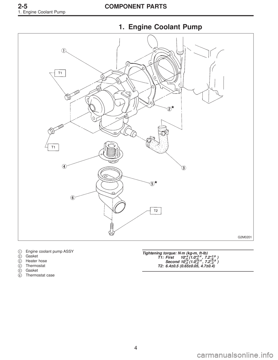
1. Engine Coolant Pump
G2M0201
�1Engine coolant pump ASSY
�
2Gasket
�
3Heater hose
�
4Thermostat
�
5Gasket
�
6Thermostat case
Tightening torque: N⋅m (kg-m, ft-lb)
T1: First 10+4
�0(1.0+0.4
�0, 7.2+2.9
�0)
Second 10+4
�0(1.0+0.4
�0, 7.2+2.9
�0)
T2: 6.4±0.5 (0.65±0.05, 4.7±0.4)
4
2-5COMPONENT PARTS
1. Engine Coolant Pump
Page 448 of 3342
G2M0210
12) Remove tensioner bracket.
13) Disconnect heater hose from engine coolant pump.
14) Remove engine coolant pump.
B: INSPECTION
1) Check engine coolant pump bearing for smooth rota-
tion.
2) Check engine coolant pump pulley for abnormalities.
G2M0211
3) Using a dial gauge, measure impeller runout in thrust
direction while rotating the pulley.
“Thrust”runout limit:
0.5 mm (0.020 in)
G2M0212
4) Check clearance between impeller and pump case.
Clearance between impeller and pump case:
Standard
0.5—0.7 mm (0.020—0.028 in)
Limit
1.0 mm (0.039 in)
5) After engine coolant pump installation, check pulley
shaft for engine coolant leaks. If leaks are noted, replace
engine coolant pump assembly.
11
2-5SERVICE PROCEDURE
2. Engine Coolant Pump
Page 458 of 3342
B2M0138
5) Disconnect heater inlet hose.
B2M0139
6) Disconnect radiator inlet hose from engine coolant pipe.
B2M0141
7) Remove bolts which install engine coolant pipe on cyl-
inder block.
B2M0141
B: INSTALLATION
1) Install engine coolant pipe on cylinder block.
Tightening torque:
6.4±0.5 N⋅m (0.65±0.05 kg-m, 4.7±0.4 ft-lb)
CAUTION:
Use a new O-ring.
B2M0139
2) Connect radiator inlet hose.
18
2-5SERVICE PROCEDURE
7. Engine Coolant Pipe
Page 459 of 3342
B2M0138
3) Connect heater inlet hose.
B2M0160
4) Install intake manifold.
G6M0095
5) Connect ground cable to battery terminal.
19
2-5SERVICE PROCEDURE
7. Engine Coolant Pipe
Page 603 of 3342
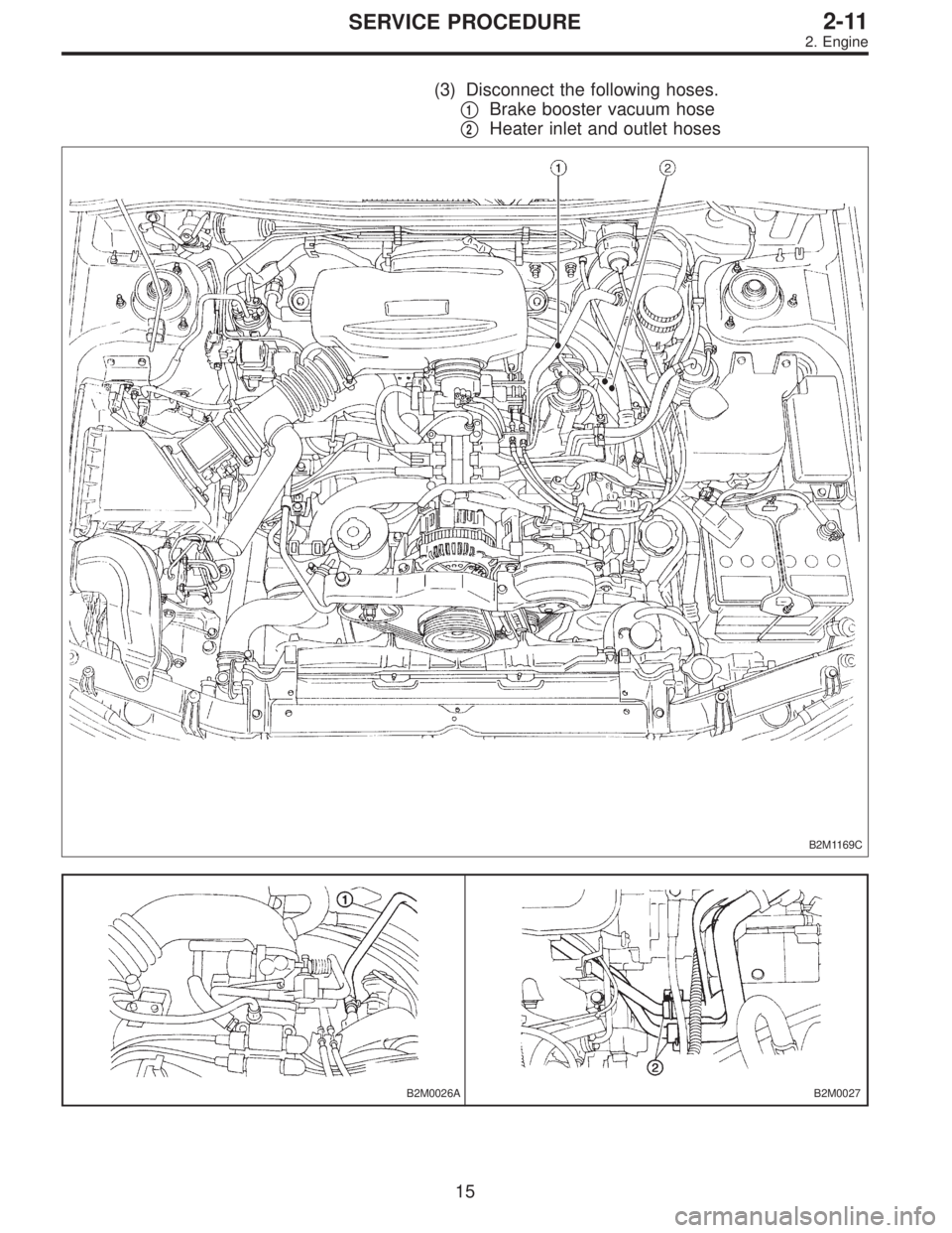
(3) Disconnect the following hoses.
�
1Brake booster vacuum hose
�
2Heater inlet and outlet hoses
B2M1169C
B2M0026AB2M0027
15
2-11SERVICE PROCEDURE
2. Engine
 Remove tensioner bracket.
13) Disconnect heater hose from engine coolant pump.
14) Remove engine coolant pump.
B: INSPECTION
1) Check engine coolant pump bearing for smooth rota-
tion.
2)")
 Disconnect heater inlet hose.
B2M0139
6) Disconnect radiator inlet hose from engine coolant pipe.
B2M0141
7) Remove bolts which install engine coolant pipe on cyl-
inder block.
B2M0141
B: I")
![SUBARU LEGACY 1997 Service Repair Manual B2M0138
3) Connect heater inlet hose.
B2M0160
4) Install intake manifold.
<Ref. to 2-7 [W4D0].>
G6M0095
5) Connect ground cable to battery terminal.
19
2-5SERVICE PROCEDURE
7. Engine Coolant Pipe](/manual-img/17/57434/w960_57434-458.png "SUBARU LEGACY 1997 Service Repair Manual B2M0138
3) Connect heater inlet hose.
B2M0160
4) Install intake manifold.
<Ref. to 2-7 [W4D0].>
G6M0095
5) Connect ground cable to battery terminal.
19
2-5SERVICE PROCEDURE
7. Engine Coolant Pipe")