Page 1893 of 3342

6. READ DATA FUNCTION KEY LIST FOR ENGINE
Function mode Contents Abbreviation Unit of measure
F00 ROM ID number YEAR—
F01 Battery voltage VB V
F02 Vehicle speed signal VSP km/h, MPH
F03 Engine speed signal EREV rpm
F04 Engine coolant temperature signal TW°C,°F
F05 Ignition signal ADVS deg
F06 Mass air flow signal QA g/s, V
F07 Throttle position signal THV %, V
F08 Injector pulse width TIM mS
F09 Idle air control signal ISC %
F10 Load data LOAD %
F11 Front oxygen sensor output signal O2 V
F12 Front oxygen sensor maximum and minimum output signal O2max - min V, V
F13 Rear oxygen sensor output signal RO2 V
F14 Rear oxygen sensor maximum and minimum output signal RO2max - min V, V
F17 Short term fuel trim ALPHA %
F19 Knock sensor signal KNOCK deg
F20 Atmospheric absolute pressure signal BARO. P kPa, mmHg
F21 Intake manifold absolute pressure signal MANI. P kPa, mmHg
F29A/F correction coefficient [short term trim] by rear oxygen sen-
sorPHOS %
F30 Long term fuel trim [A/F learning correction coefficient] KBLRC %
F31 Long term fuel trim whole [A/F learning control coefficient] K0 %
F32 Front oxygen sensor heater current FO2H A
F33 Rear oxygen sensor heater current RO2H A
F35 Purge control solenoid valve duty ratio CPCD %
F36Maximum value of cylinder #1 misfire times during 100 rota-
tionsMF1 %
F37Maximum value of cylinder #2 misfire times during 100 rota-
tionsMF2 %
F38Maximum value of cylinder #3 misfire times during 100 rota-
tionsMF3 %
F39Maximum value of cylinder #4 misfire times during 100 rota-
tionsMF4 %
F42Maximum and minimum EGR system pressure value (AT
vehicles)EGRmax - min kPa
F43 Fuel tank pressure signal TNKP kPa, mmHg
F44 Fuel temperature signal TNKT°C,°F
F45 Fuel level signal FLEVEL V
FA 0 O N)OFF signal——
FA 1 O N)OFF signal——
FA 2 O N)OFF signal——
FA 3 O N)OFF signal——
FA 4 O N)OFF signal——
FA 5 O N)OFF signal——
FB0 Diagnostic trouble code (DTC) INSPECT—
FB1 Diagnostic trouble code (DTC) OBD—
42
2-7ON-BOARD DIAGNOSTICS II SYSTEM
3. Diagnosis System
Page 1900 of 3342
B2M0497
29. FUNCTION MODE: F32
—FRONT OXYGEN SENSOR HEATER CURRENT
(FO2H)—
B2M0498
30. FUNCTION MODE: F33
—REAR OXYGEN SENSOR HEATER CURRENT
(RO2H)—
H2M1325
31. FUNCTION MODE: F35
—PURGE CONTROL SOLENOID VALVE DUTY RATIO
(CPCD)—
B2M0499
32. FUNCTION MODE: F36
—MAXIMUM VALUE OF CYLINDER #1 MISFIRE RATE
DURING 100 ROTATIONS (MF1)—
B2M0500
33. FUNCTION MODE: F37
—MAXIMUM VALUE OF CYLINDER #2 MISFIRE RATE
DURING 100 ROTATIONS (MF2)—
49
2-7ON-BOARD DIAGNOSTICS II SYSTEM
3. Diagnosis System
Page 1931 of 3342

Note
Ignition SW ON
(Engine OFF)Engine ON (Idling)
Knock
sensorSignal B84 3 2.8 2.8—
Shield B84 56 0 0—
AT/MT identification B84 81(AT) 5
(MT) 0(AT) 5
(M")
ContentConnector
No.Terminal
No.Signal (V)
Note
Ignition SW ON
(Engine OFF)Engine ON (Idling)
Knock
sensorSignal B84 3 2.8 2.8—
Shield B84 56 0 0—
AT/MT identification B84 81(AT) 5
(MT) 0(AT) 5
(MT) 0When measuring voltage between
ECM and body.
Back-up power supply B84 39 10—13 13—14 Ignition switch“OFF”:10—13
Control unit power supply B841
10—13 13—14—
2
Ignition
control#1,#2 B84 41 0 1—3.4—
#3,#4 B84 40 0 1—3.4—
Fuel
injector# 1 B84 96 10—13 1—14 Waveform
# 2 B84 70 10—13 1—14 Waveform
# 3 B84 44 10—13 1—14 Waveform
# 4 B84 16 10—13 1—14 Waveform
Idle air
control
solenoid
valveOPEN end B84 14—1—13 Waveform
CLOSE end B84 13—13—1 Waveform
Fuel pump relay control B84 32ON: 0.5, or less
OFF: 10—130.5, or less—
A/C relay control B84 31ON: 0.5, or less
OFF: 10—13ON: 0.5, or less
OFF: 13—14—
Radiator fan relay 1
controlB84 74ON: 0.5, or less
OFF: 10—13ON: 0.5, or less
OFF: 13—14—
Radiator fan relay 2
controlB84 73ON: 0.5, or less
OFF: 10—13ON: 0.5, or less
OFF: 13—14With A/C vehicles only
Self-shutoff control B84 63 10—13 13—14—
Malfunction indicator lamp B84 58——Light“ON”:1,orless
Light“OFF”:10—14
Engine speed output B84 64—0—13, or more Waveform
Torque control signal B84 79 5 5—
Mass air flow signal for
ATB84 47 0—0.3 0.8—1.2—
Purge control solenoid
valveB84 72ON: 1, or less
OFF: 10—13ON: 1, or less
OFF: 13—14—
Atmospheric pressure
sensorB84 26 3.9—4.1 2.0—2.3—
Pressure sources
switching solenoid valveB84 15ON: 1, or less
OFF: 10—13ON: 1, or less
OFF: 13—14—
EGR solenoid valve B84 71ON: 1, or less
OFF: 10—13ON: 1, or less
OFF: 13—14—
Front oxygen sensor
heater signalB84 38 0—1.0 0—1.0—
Rear oxygen sensor
heater signalB84 37 0—1.0 0—1.0—
Fuel temperature sensor B84 25 2.5—3.8 2.5—3.8�2200 cc AWD except Taiwan
spec. vehicles
�Ambient temperature: 25°C
(77°F)
Fuel level sensor B84 27 0.12—4.75 0.12—4.75 2200 cc AWD except Taiwan model
Fuel tank
pressure
sensorSignal B84 4 2.3—2.7 2.3—2.7�2200 cc AWD except Taiwan
spec. vehicles
�The value obtained after the fuel
filler cap was removed once and
recapped.
Power
supplyB84 21 5 5—
GND B84 20 0 0—
Fuel tank pressure control
solenoid valveB84 10ON: 1, or less
OFF: 10—13ON: 1, or less
OFF: 13—142200 cc AWD except Taiwan spec.
vehicles
Vent control solenoid
valveB84 35ON: 1, or less
OFF: 10—13ON: 1, or less
OFF: 13—142200 cc AWD except Taiwan spec.
vehicles
TCS signal B84 61 0—70—7 Waveform
80
2-7ON-BOARD DIAGNOSTICS II SYSTEM
5. Specified Data
Page 1932 of 3342
ContentConnector
No.Terminal
No.Signal (V)
Note
Ignition SW ON
(Engine OFF)Engine ON (Idling)
AT diagnosis input signal B84 80Less than 1)More
than 4Less than 1)More
than 4Waveform
GND (sensors) B84 20 0 0—
GND (injectors) B8469
00—
95
GND (ignition system) B84 94 0 0—
GND (power supply) B8419
00—
46
GND (control systems) B8417
00—
18
GND (oxygen sensor
heater)B84 42 0 0—
2. ENGINE CONDITION DATA
Content Model Specified data
Mass air flow2200 cc1.7—3.3 (g/sec): Idling
7.1—14.2 (g/sec): 2,500 rpm racing
2500 cc2.2—4.2 (g/sec): Idling
8.6—14.5 (g/sec): 2,500 rpm racing
Engine load2200 cc1.6—2.9 (%): Idling
6.4—12.8 (%): 2,500 rpm racing
2500 cc1.9—3.5 (%): Idling
7.2—12.1 (%): 2,500 rpm racing
Measuring condition:
�After warm-up the engine.
�Gear position is in“N”or“P”position.
�A/C is turned OFF.
�All accessory switches are turned OFF.
81
2-7ON-BOARD DIAGNOSTICS II SYSTEM
5. Specified Data
Page 1980 of 3342
 LIST
DTC
No.Abbreviation
(Subaru Select Monitor)Item Page
P0101 QA
—RLOW Mass air flow sensor circuit range/p")
10. Diagnostic Chart with Trouble Code
for LHD Vehicles
A: DIAGNOSTIC TROUBLE CODE (DTC) LIST
DTC
No.Abbreviation
(Subaru Select Monitor)Item Page
P0101 QA
—RLOW Mass air flow sensor circuit range/performance problem (low input) 132
P0102 QA
—LOW Mass air flow sensor circuit low input 134
P0103 QA
—HI Mass air flow sensor circuit high input 138
P0106 PS
—R2 Pressure sensor circuit range/performance problem 141
P0107 P
—SLOW Pressure sensor circuit low input 145
P0108 P
—SHI Pressure sensor circuit high input 149
P0116 TW
—LOW Engine coolant temperature sensor circuit low input 154
P0117 TW
—HI Engine coolant temperature sensor circuit high input 157
P0121 TH
—RHI Throttle position sensor circuit range/performance problem (high input) 160
P0122 THV
—LOW Throttle position sensor circuit low input 162
P0123 THV
—HI Throttle position sensor circuit high input 167
P0125 TW
—CL Insufficient coolant temperature for closed loop fuel control 170
P0130 FO2
—V Front oxygen sensor circuit malfunction 172
P0133 FO2
—R Front oxygen sensor circuit slow response 175
P0135 FO2H Front oxygen sensor heater circuit malfunction 177
P0136 RO2
—V Rear oxygen sensor circuit malfunction 181
P0139 RO2
—R Rear oxygen sensor circuit slow response 184
P0141 RO2H Rear oxygen sensor heater circuit malfunction 186
P0170 FUEL Fuel trim malfunction 190
P0181 TNKT
—F Fuel temperature sensor A circuit range/performance problem 195
P0182 TNKT
—LOW Fuel temperature sensor A circuit low input 197
P0183 TNKT
—HI Fuel temperature sensor A circuit high input 200
P0261 INJ1 Fuel injector circuit low input - #1 203
P0262 INJ1
—HI Fuel injector circuit high input - #1 207
P0264 INJ2 Fuel injector circuit low input - #2 203
P0265 INJ2
—HI Fuel injector circuit high input - #2 207
P0267 INJ3 Fuel injector circuit low input - #3 203
P0268 INJ3
—HI Fuel injector circuit high input - #3 207
P0270 INJ4 Fuel injector circuit low input - #4 203
P0271 INJ4
—HI Fuel injector circuit high input - #4 207
P0301 MIS
—1 Cylinder 1 misfire detected 211
P0302 MIS
—2 Cylinder 2 misfire detected 211
P0303 MIS
—3 Cylinder 3 misfire detected 211
P0304 MIS
—4 Cylinder 4 misfire detected 211
P0325 KNOCK Knock sensor circuit malfunction 219
P0335 CRANK Crankshaft position sensor circuit malfunction 222
P0336 CRANK
—R Crankshaft position sensor circuit range/performance problem 225
P0340 CAM Camshaft position sensor circuit malfunction 227
129
2-7ON-BOARD DIAGNOSTICS II SYSTEM
10. Diagnostic Chart with Trouble Code for LHD Vehicles
Page 2028 of 3342
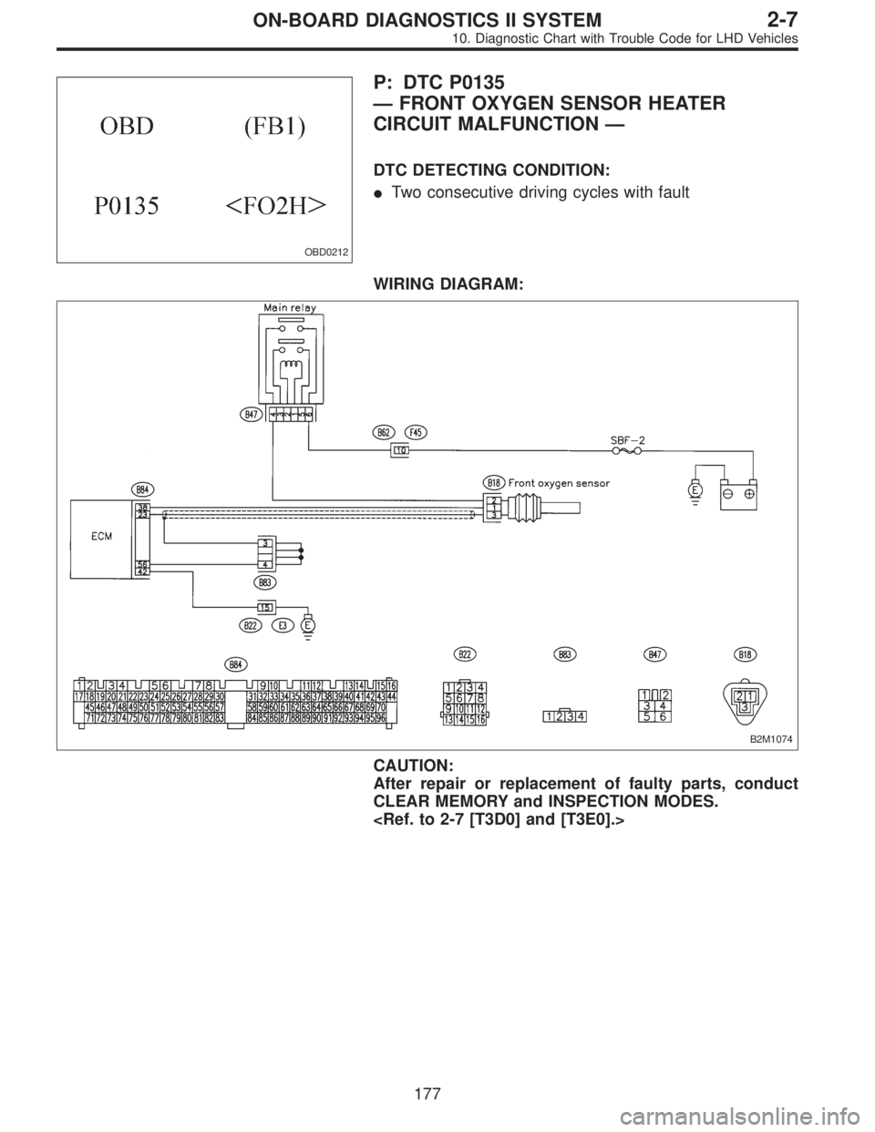
OBD0212
P: DTC P0135
—FRONT OXYGEN SENSOR HEATER
CIRCUIT MALFUNCTION—
DTC DETECTING CONDITION:
�Two consecutive driving cycles with fault
WIRING DIAGRAM:
B2M1074
CAUTION:
After repair or replacement of faulty parts, conduct
CLEAR MEMORY and INSPECTION MODES.
177
2-7ON-BOARD DIAGNOSTICS II SYSTEM
10. Diagnostic Chart with Trouble Code for LHD Vehicles
Page 2029 of 3342
.
: Go to step10P2.
B2M0547A
1) Turn ig")
10P1
CHECK DTC P0141 ON DISPLAY.
: Does the Subaru select monitor or OBD-II
general scan tool indicate DTC P0135 and
P0141 at the same time?
: Go to next step 1).
: Go to step10P2.
B2M0547A
1) Turn ignition switch to OFF.
2) Disconnect connector from ECM.
3) Measure resistance of harness between ECM connec-
tor and chassis ground.
: Connector & terminal
(B84) No. 42—Chassis ground:
Is the resistance less than 5Ω?
: Repair poor contact in ECM connector.
: Repair harness and connector.
NOTE:
In this case, repair the following:
�Open circuit in harness between ECM and coupling con-
nector (B22)
�Open circuit in harness between coupling connector
(B22) and engine grounding terminal
�Poor contact in front oxygen sensor connector
�Poor contact in coupling connector (B22)
OBD0145A
10P2CONNECT SUBARU SELECT MONITOR
OR THE OBD-II GENERAL SCAN TOOL,
AND READ DATA.
1) Turn ignition switch to OFF.
2) Connect Subaru Select Monitor or the OBD-II general
scan tool to data link connector.
3) Turn ignition switch to ON and Subaru Select Monitor or
OBD-II general scan tool switch to ON.
4) Start engine.
B2M0497
5) Read data on Subaru Select Monitor or OBD-II general
scan tool.
�Subaru Select Monitor
Designate mode using function key.
Function mode: F32
�F32: Front oxygen sensor heater current is indicated.
: Is the value more than 0.2 A in function
mode F32?
: Repair connector.
178
2-7ON-BOARD DIAGNOSTICS II SYSTEM
10. Diagnostic Chart with Trouble Code for LHD Vehicles
Page 2037 of 3342
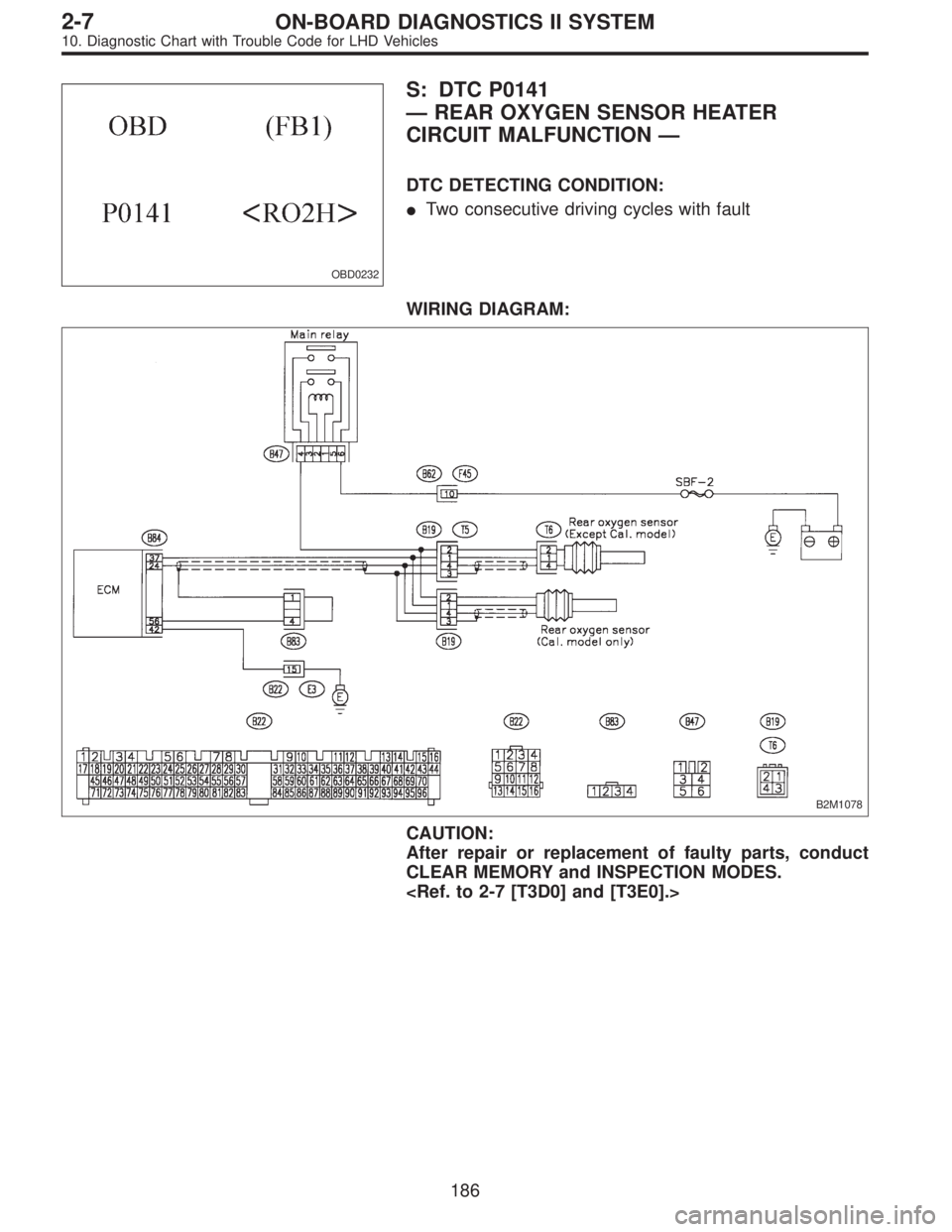
OBD0232
S: DTC P0141
—REAR OXYGEN SENSOR HEATER
CIRCUIT MALFUNCTION—
DTC DETECTING CONDITION:
�Two consecutive driving cycles with fault
WIRING DIAGRAM:
B2M1078
CAUTION:
After repair or replacement of faulty parts, conduct
CLEAR MEMORY and INSPECTION MODES.
186
2-7ON-BOARD DIAGNOSTICS II SYSTEM
10. Diagnostic Chart with Trouble Code for LHD Vehicles
—
B2M0498
30. FUNCTION MODE: F33
—REAR OXYGEN SENSOR HEATER CURRENT
(RO2H)—
H2M1325
31. FUNCTION MODE: F35
—PURGE CON")

Note
Ignition SW ON
(Engine OFF)Engine ON (Idling)
AT diagnosis input signal B84 80Less than 1)More
than 4Less than 1)More
than 4Waveform
GND (sensors) B84 2")