Page 1442 of 3342
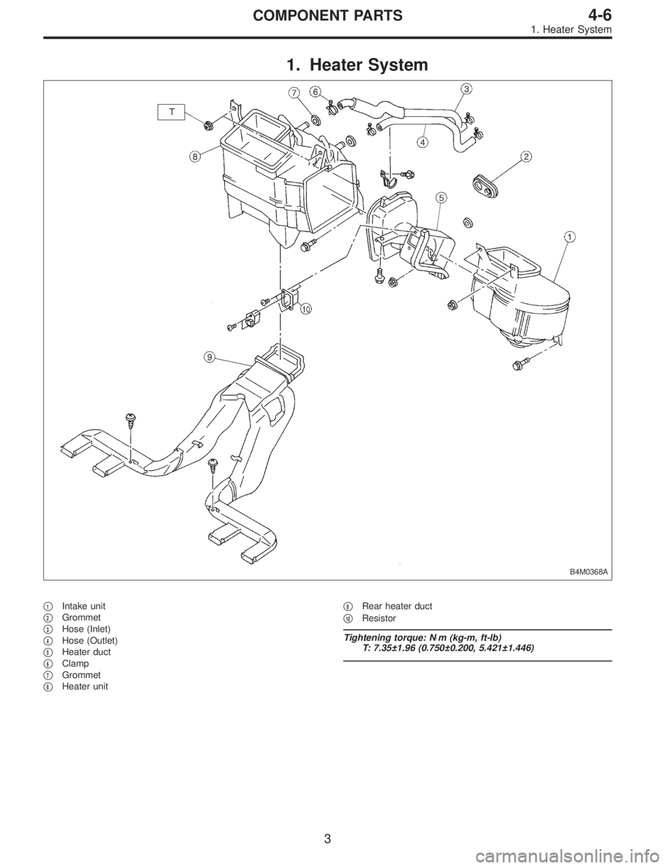
1. Heater System
B4M0368A
�1Intake unit
�
2Grommet
�
3Hose (Inlet)
�
4Hose (Outlet)
�
5Heater duct
�
6Clamp
�
7Grommet
�
8Heater unit�
9Rear heater duct
�
10Resistor
Tightening torque: N⋅m (kg-m, ft-lb)
T: 7.35±1.96 (0.750±0.200, 5.421±1.446)
3
4-6COMPONENT PARTS
1. Heater System
Page 1443 of 3342
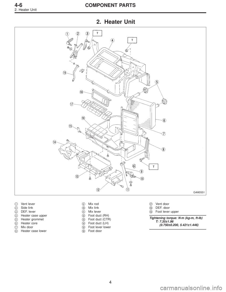
2. Heater Unit
G4M0551
�1Vent lever
�
2Side link
�
3DEF. lever
�
4Heater case upper
�
5Heater grommet
�
6Heater core
�
7Mix door
�
8Heater case lower�
9Mix rod
�
10Mix link
�
11Mix lever
�
12Foot duct (RH)
�
13Foot duct (CTR)
�
14Foot duct (LH)
�
15Foot lever lower
�
16Foot door�
17Vent door
�
18DEF. door
�
19Foot lever upper
Tightening torque: N⋅m (kg-m, ft-lb)
T: 7.35±1.96
(0.750±0.200, 5.421±1.446)
4
4-6COMPONENT PARTS
2. Heater Unit
Page 1446 of 3342
1. Supplemental Restraint System
“Airbag”
Airbag system wiring harness is routed near the instrument
panel, heater unit, blower motor and control unit.
CAUTION:
�All Airbag system wiring harness and connectors
are colored yellow. Do not use electrical test equip-
ment on these circuit.
�Be careful not to damage Airbag system wiring har-
ness when servicing the instrument panel, heater unit,
blower motor and control unit.
2. Heater Unit
A: REMOVAL AND INSTALLATION
1) Disconnect GND cable from battery.
2) Remove heater hoses (inlet, outlet) in engine compart-
ment.
NOTE:
Drain as much coolant from heater unit as possible, and
plug disconnected hose with cloth.
3) Remove instrument panel.
4) Remove steering support beam.
5) Remove evaporator. (With A/C model)
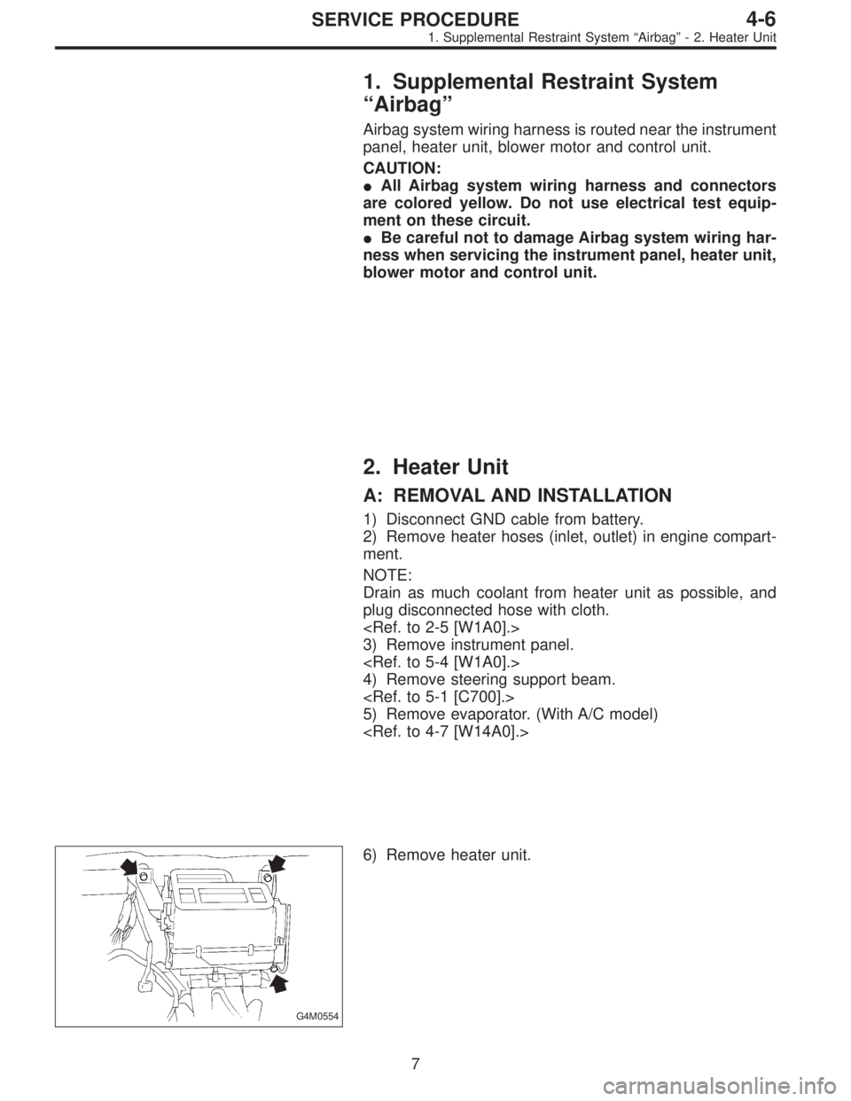
G4M0554
6) Remove heater unit.
7
4-6SERVICE PROCEDURE
1. Supplemental Restraint System“Airbag”- 2. Heater Unit
Page 1447 of 3342
1. Supplemental Restraint System
“Airbag”
Airbag system wiring harness is routed near the instrument
panel, heater unit, blower motor and control unit.
CAUTION:
�All Airbag system wiring harness and connectors
are colored yellow. Do not use electrical test equip-
ment on these circuit.
�Be careful not to damage Airbag system wiring har-
ness when servicing the instrument panel, heater unit,
blower motor and control unit.
2. Heater Unit
A: REMOVAL AND INSTALLATION
1) Disconnect GND cable from battery.
2) Remove heater hoses (inlet, outlet) in engine compart-
ment.
NOTE:
Drain as much coolant from heater unit as possible, and
plug disconnected hose with cloth.
3) Remove instrument panel.
4) Remove steering support beam.
5) Remove evaporator. (With A/C model)
G4M0554
6) Remove heater unit.
7
4-6SERVICE PROCEDURE
1. Supplemental Restraint System“Airbag”- 2. Heater Unit
Page 1448 of 3342
7) Installation is in the reverse order of removal.
Fitted length of heater hose over pipe:
25 — 30 mm (0.98 — 1.18 in)
8) Pour coolant.
B5M0025
3. Blower Motor Assembly
A: REMOVAL AND INSTALLATION
1) Disconnect GND cable from battery.
2) Remove glove box and pocket back panel.
[W1A0].>
3) Disconnect blower motor harness connector.
G4M0555
4) Disconnect aspirator pipe�1.
5) Remove blower motor mounting screw.
6) Remove blower motor assembly.
7) Installation is in the reverse order of removal.
8
4-6SERVICE PROCEDURE
2. Heater Unit - 3. Blower Motor Assembly
Page 1449 of 3342
7) Installation is in the reverse order of removal.
Fitted length of heater hose over pipe:
25 — 30 mm (0.98 — 1.18 in)
8) Pour coolant.
B5M0025
3. Blower Motor Assembly
A: REMOVAL AND INSTALLATION
1) Disconnect GND cable from battery.
2) Remove glove box and pocket back panel.
[W1A0].>
3) Disconnect blower motor harness connector.
G4M0555
4) Disconnect aspirator pipe�1.
5) Remove blower motor mounting screw.
6) Remove blower motor assembly.
7) Installation is in the reverse order of removal.
8
4-6SERVICE PROCEDURE
2. Heater Unit - 3. Blower Motor Assembly
Page 1450 of 3342
B5M0027
4. Control Unit
A: REMOVAL
1) Disconnect GND cable from battery.
2) Set temperature control lever to“FULL COLD”position.
3) Remove temperature control cable from heater unit.
NOTE:
Do not attempt to move link of heater unit during installa-
tion.
B4M0370
4) Remove cup holder.
5) Remove center panel and then disconnect connector.
B4M0059
6) Remove control unit assembly and disconnect connec-
tor.
B4M0060A
B: INSPECTION
1. FAN SWITCH
Check continuity between terminals at each switch posi-
tion.
Switch
positionTerminals
123456
1��
�
2���
3���
4���
GND IGN
9
4-6SERVICE PROCEDURE
4. Control Unit
Page 1452 of 3342
B5M0025
5. Intake Door Motor
A: REMOVAL
1) Disconnect GND cable from battery.
2) Remove glove box and pocket back panel.
[W1A0].>
3) Remove heater duct or evaporator. (With A/C model).
G4M0561
4) Remove intake unit from the vehicle.
B4M1428A
5) Remove screws which secure intake door motor to
intake unit.
NOTE:
Ensure that RECIRC switch is set to“ON”.
B4M1429A
11
4-6SERVICE PROCEDURE
5. Intake Door Motor

![SUBARU LEGACY 1997 Service Repair Manual 7) Installation is in the reverse order of removal.
Fitted length of heater hose over pipe:
25 — 30 mm (0.98 — 1.18 in)
8) Pour coolant. <Ref. to 2-5 [W1B0].>
B5M0025
3. Blower Motor Assembly
A: R](/manual-img/17/57434/w960_57434-1447.png "SUBARU LEGACY 1997 Service Repair Manual 7) Installation is in the reverse order of removal.
Fitted length of heater hose over pipe:
25 — 30 mm (0.98 — 1.18 in)
8) Pour coolant. <Ref. to 2-5 [W1B0].>
B5M0025
3. Blower Motor Assembly
A: R")
![SUBARU LEGACY 1997 Service Repair Manual 7) Installation is in the reverse order of removal.
Fitted length of heater hose over pipe:
25 — 30 mm (0.98 — 1.18 in)
8) Pour coolant. <Ref. to 2-5 [W1B0].>
B5M0025
3. Blower Motor Assembly
A: R](/manual-img/17/57434/w960_57434-1448.png "SUBARU LEGACY 1997 Service Repair Manual 7) Installation is in the reverse order of removal.
Fitted length of heater hose over pipe:
25 — 30 mm (0.98 — 1.18 in)
8) Pour coolant. <Ref. to 2-5 [W1B0].>
B5M0025
3. Blower Motor Assembly
A: R")
 Disconnect GND cable from battery.
2) Set temperature control lever to“FULL COLD”position.
3) Remove temperature control cable from heater unit.
NOTE:
Do not")
![SUBARU LEGACY 1997 Service Repair Manual B5M0025
5. Intake Door Motor
A: REMOVAL
1) Disconnect GND cable from battery.
2) Remove glove box and pocket back panel. <Ref. to 5-4
[W1A0].>
3) Remove heater duct or evaporator. (With A/C model).
<R](/manual-img/17/57434/w960_57434-1451.png "SUBARU LEGACY 1997 Service Repair Manual B5M0025
5. Intake Door Motor
A: REMOVAL
1) Disconnect GND cable from battery.
2) Remove glove box and pocket back panel. <Ref. to 5-4
[W1A0].>
3) Remove heater duct or evaporator. (With A/C model).
<R")