Page 2148 of 3342

10BH1
CHECK OPERATION OF BRAKE LIGHT.
: Does brake light come on when depressing
the brake pedal?
: Go to step10BH2.
: Repair or replace brake light circuit.
OBD0589A
10BH2CHECK HARNESS BETWEEN TCM AND
BRAKE LIGHT SWITCH CONNECTOR.
1) Disconnect connectors from TCM and brake light
switch.
2) Measure resistance of harness between TCM and
brake light switch connector.
: Connector & terminal
(B56) No. 7—(B64) No. 2:
(B56) No. 7—(B65) No. 3 (With cruise con-
trol):
(B56) No. 7—(B67) No. 2 (With traction
control):
Is the resistance less than 1Ω?
: Go to next step 3).
: Repair or replace harness and connector.
NOTE:
In this case, repair the following:
�Open circuit in harness between TCM and brake light
switch connector
�Poor contact in TCM connector
�Poor contact in brake light switch connector
OBD0590A
3) Measure resistance of harness between TCM and
chassis ground.
: Connector & terminal
(B56) No. 7—Chassis ground:
Is the resistance more than 1 MΩ?
: Go to step10BH3.
: Repair ground short circuit in harness between
TCM and brake light switch connector.
297
2-7ON-BOARD DIAGNOSTICS II SYSTEM
10. Diagnostic Chart with Trouble Code for LHD Vehicles
Page 2262 of 3342
B2M0669
CZ: DTC P1701
—CRUISE CONTROL SET SIGNAL CIRCUIT
MALFUNCTION FOR AUTOMATIC
TRANSMISSION—
DTC DETECTING CONDITION:
�Two consecutive driving cycles with fault
WIRING DIAGRAM:
OBD0512
CAUTION:
After repair or replacement of faulty parts, conduct
CLEAR MEMORY and INSPECTION MODES.
OBD0514A
10CZ1CHECK HARNESS BETWEEN TCM AND
CCM CONNECTOR.
1) Turn ignition switch to OFF.
2) Disconnect connectors from TCM and CCM.
3) Measure resistance of harness between TCM and CCM
connector.
411
2-7ON-BOARD DIAGNOSTICS II SYSTEM
10. Diagnostic Chart with Trouble Code for LHD Vehicles
Page 2263 of 3342
 No. 3—(B94) No. 3:
Is the resistance less than 1Ω?
: Go to next step 4).
: Repair open circuit in harness between TCM and
CCM connector.
OBD0515A
4) Measure resistance")
: Connector & terminal
(B56) No. 3—(B94) No. 3:
Is the resistance less than 1Ω?
: Go to next step 4).
: Repair open circuit in harness between TCM and
CCM connector.
OBD0515A
4) Measure resistance of harness between TCM and
chassis ground.
: Connector & terminal
(B56) No. 3—Chassis ground:
Is the resistance less than 10Ω?
: Repair short circuit in harness between TCM and
CCM connector.
: Go to step10CZ2.
OBD0513A
10CZ2
CHECK INPUT SIGNAL FOR TCM.
1) Connect connector to TCM and CCM.
2) Lift-up the vehicle or set the vehicle on free rollers.
CAUTION:
On AWD models, raise all wheels off ground.
3) Start the engine.
4) Cruise control main switch to ON.
5) TCS OFF switch to ON. (with TCS models only)
6) Move selector lever to“D”and slowly increase vehicle
speed to 50 km/h (31 MPH).
7) Cruise control set switch to ON.
8) Measure voltage between TCM and chassis ground.
: Connector & terminal
(B56) No. 3 (+)—Chassis ground (�):
Is the resistance less than 1 V?
: Go to next.
: Check cruise control set circuit.
[T7A0].>
: Is there poor contact in TCM connector?
: Repair poor contact in TCM connector.
: Replace TCM.
412
2-7ON-BOARD DIAGNOSTICS II SYSTEM
10. Diagnostic Chart with Trouble Code for LHD Vehicles
Page 2276 of 3342
Item Page
P1122 BR
—HI Pressure sources switching solenoid valve circuit high input 523
P1141 QA
—RHI Mass air flow sensor circuit range/performance prob")
DTC
No.Abbreviation
(Subaru Select Monitor)Item Page
P1122 BR
—HI Pressure sources switching solenoid valve circuit high input 523
P1141 QA
—RHI Mass air flow sensor circuit range/performance problem (high input) 524
P1142 TH
—RLOW Throttle position sensor circuit range/performance problem (low input) 525
P1143 PS
—RLOW Pressure sensor circuit range/performance problem (low input) 526
P1144 PS
—RHI Pressure sensor circuit range/performance problem (high input) 527
P1400 PCVSOL
—LO Fuel tank pressure control solenoid valve circuit low input 528
P1420 PCVSOL
—HI Fuel tank pressure control solenoid valve circuit high input 532
P1421 EGRSOL
—HI Exhaust gas recirculation circuit high input 535
P1422 CPC
—HI Evaporative emission control system purge control valve circuit high input 536
P1423 VCMSOL
—HI Evaporative emission control system vent control high input 537
P1440 PCV
—FLOW Fuel tank pressure control system function problem (low input) 540
P1441 PCV
—FHI Fuel tank pressure control system function problem (high input) 541
P1442 FLVL
—R2 Fuel level sensor circuit range/performance problem 2 542
P1500 FAN
—1 Radiator fan relay 1 circuit low input 544
P1502 FAN
—F Radiator fan function problem 545
P1507 ISC
—SHI Idle control system malfunction (fail-safe) 546
P1520 FAN
—1HI Radiator fan relay 1 circuit high input 547
P1540 VSP
—S Vehicle speed sensor malfunction 2 548
P1700 ATTH Throttle position sensor circuit malfunction for automatic transmission 549
P1701 ATCRS Cruise control set signal circuit malfunction for automatic transmission 550
P1702 ATDIAG
—LO Automatic transmission diagnosis input signal circuit low input 551
P1722 ATDIAG
—HI Automatic transmission diagnosis input signal circuit high input 552
P1742 ATDIAG
—2 Automatic transmission diagnosis input signal circuit malfunction 553
425
2-7ON-BOARD DIAGNOSTICS II SYSTEM
11. Diagnostic Chart with Trouble Code for RHD Vehicles
Page 2401 of 3342
B2M0669
CW: DTC P1701
—CRUISE CONTROL SET SIGNAL CIRCUIT
MALFUNCTION—
WIRING DIAGRAM:
OBD0512
NOTE:
Check cruise control set signal circuit.
550
2-7ON-BOARD DIAGNOSTICS II SYSTEM
11. Diagnostic Chart with Trouble Code for RHD Vehicles
Page 2412 of 3342
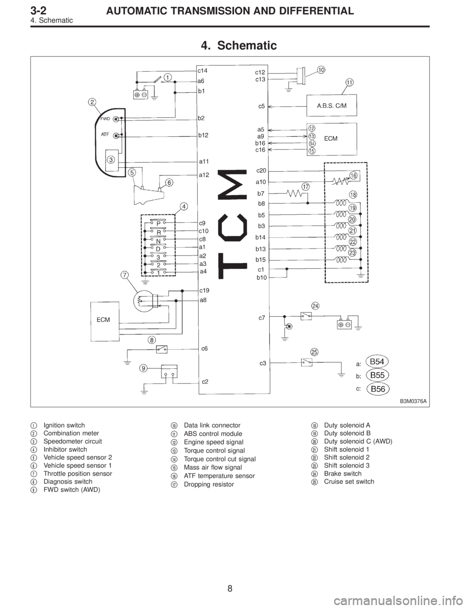
4. Schematic
B3M0376A
�1Ignition switch
�
2Combination meter
�
3Speedometer circuit
�
4Inhibitor switch
�
5Vehicle speed sensor 2
�
6Vehicle speed sensor 1
�
7Throttle position sensor
�
8Diagnosis switch
�
9FWD switch (AWD)�
10Data link connector
�
11ABS control module
�
12Engine speed signal
�
13Torque control signal
�
14Torque control cut signal
�
15Mass air flow signal
�
16ATF temperature sensor
�
17Dropping resistor�
18Duty solenoid A
�
19Duty solenoid B
�
20Duty solenoid C (AWD)
�
21Shift solenoid 1
�
22Shift solenoid 2
�
23Shift solenoid 3
�
24Brake switch
�
25Cruise set switch
8
3-2AUTOMATIC TRANSMISSION AND DIFFERENTIAL
4. Schematic
Page 2414 of 3342
Resistance to
body
(ohms)
Throttle position
sensorB54 8Throttle fully closed. 0.5±0.2
—
Throttle fully open. 4.6±0.3
Throttle positio")
ContentConnector
No.Terminal
No.Measuring conditionsVoltage
(V)Resistance to
body
(ohms)
Throttle position
sensorB54 8Throttle fully closed. 0.5±0.2
—
Throttle fully open. 4.6±0.3
Throttle position
sensor power
supplyB56 19Ignition switch ON
(With engine OFF)5.05±0.25—
ATF temperature
sensorB54 10ATF temperature 20°C(68°F) 3.45±0.55 2.1—2.9 k
ATF temperature 80°C (176°F) 1.2±0.2 275—375
Vehicle speed
sensor 1B54 12Vehicle stopped. 0
450—720
Vehicle speed at least 20 km/h (12
MPH)More than 1 (AC range)
Vehicle speed
sensor 2B56 11When vehicle is slowly moved at
least 2 meters (7ft).Less than 1)More than 9—
Engine speed
signalB54 5Ignition switch ON (with engine
OFF).More than 10.5
—
Ignition switch ON (with engine ON). 8—11
Cruise set signal B56 3When cruise control is set (SET
lamp ON).Less than 1
—
When cruise control is not set (SET
lamp OFF).More than 6.5
Torque control
signalB55 16 Ignition switch ON 5±1—
Torque control cut
signalB56 16 Ignition switch ON 6—9—
Mass air flow
signalB54 9 Engine idling after warm-up 0.5—1.2—
Shift solenoid 1 B55 141st or 4th gear More than 9
20—32
2nd or 3rd gear Less than 1
Shift solenoid 2 B55 131st or 2nd gear More than 9
20—32
3rd or 4th gear Less than 1
Shift solenoid 3 B55 15Select lever in“N”range (with
throttle fully closed).Less than 1
20—32
Select lever in“D”range (with
throttle fully closed).More than 9
Duty solenoid A B55 8Throttle fully closed (with engine
OFF) after warm-up.1.5—4.0
2.0—4.5
Throttle fully open (with engine
OFF) after warm-up.Less than 1
Dropping resistor B55 7Throttle fully closed (with engine
OFF) after warm-up.More than 8.5
12—18
Throttle fully open (with engine
OFF) after warm-up.Less than 1
Duty solenoid B B55 5When lock up occurs. More than 8.5
9—17
When lock up is released. Less than 0.5
Duty solenoid C
(AWD model only)B55 3Fuse on FWD switch More than 8.5
9—17 Fuse removed from FWD switch
(with throttle fully open and with
select lever in 1st gear).Less than 0.5
Sensor ground
line 1B54 7—0 Less than 1
Sensor ground
line 2B56 20—0 Less than 1
System ground
lineB56 1—0 Less than 1
Power system
ground lineB55 10—0 Less than 1
FWD switch
(AWD model only)B56 2Fuse removed. 6—9.1
—
Fuse installed. Less than 1
10
3-2AUTOMATIC TRANSMISSION AND DIFFERENTIAL
5. Transmission Control Module (TCM) I/O Signal
Page 2460 of 3342

2. ON←→OFF SIGNAL LIST
Mode LED No. Signal name Display LED“ON”requirements Page
FA 01 FWD switch FF When fuse is installed in FWD switch.—
2 Kick-down switch KD—
3—— —
4—— —
5 Brake switch BR When brake switch is turned ON.—
6 ABS switch AB When ABS signal is entered.—
7 Cruise control set CR When cruise control is set.—
8 Power switch PW—
9—— —
10—— —
FA 11 P/N range switch NP When P or N range is selected.—
2 R range switch RR When R range is selected.—
3 D range switch RD When D range is selected.—
4 3 range switch R3 When 3 range is selected.—
5 2 range switch R2 When 2 range is selected.—
6 1 range switch R1 When 1 range is selected.—
7 Diagnosis switch SS When diagnosis switch is turned ON. 66
8—— —
9—— —
10—— —
NOTE; LED Nos. 2 and 8 cannot be turned on.
3. DIAGNOSIS MODE
Mode Contents Abbr. Contents of display
FB0On-board
diagnosticsDIAG.U Current trouble code determined by on-board diagnostics.
FB1On-board
diagnosticsDIAG.MPrevious trouble code stored in memory by on-board
diagnostics.
FC0 Back-up clear—Function of clearing trouble code stored in memory.
56
3-2AUTOMATIC TRANSMISSION AND DIFFERENTIAL
8. Diagnostic Chart with Select Monitor
![SUBARU LEGACY 1997 Service Repair Manual B2M0669
CW: DTC P1701
—CRUISE CONTROL SET SIGNAL CIRCUIT
MALFUNCTION—
WIRING DIAGRAM:
OBD0512
NOTE:
Check cruise control set signal circuit.
<Ref. to 2-7 [T10CZ0].>
550
2-7ON-BOARD DIAGNOSTICS II](/manual-img/17/57434/w960_57434-2400.png "SUBARU LEGACY 1997 Service Repair Manual B2M0669
CW: DTC P1701
—CRUISE CONTROL SET SIGNAL CIRCUIT
MALFUNCTION—
WIRING DIAGRAM:
OBD0512
NOTE:
Check cruise control set signal circuit.
<Ref. to 2-7 [T10CZ0].>
550
2-7ON-BOARD DIAGNOSTICS II")