Page 1795 of 3342
B6M0358
3) Remove nuts which secure actuator.
4) Remove actuator while disconnecting vacuum hose.
Tightening torque:
7.4±1.5 N⋅m (0.75±0.15 kg-m, 5.4±1.1 ft-lb)
B6M0359A
4. VACUUM PUMP AND VALVES
1) Disconnect connector from vacuum pump.
2) Remove bolts which secure vacuum pump.
3) Remove A/C receiver/drier bracket.
4) Remove vacuum pump while disconnecting vacuum
hose.
Tightening torque:
7.4±1.5 N⋅m (0.75±0.15 kg-m, 5.4±1.1 ft-lb)
5. STOP AND BRAKE SWITCH
Refer to 4-5 [C101] (MT) or 4-5 [C201] (AT) as for removal
and installation of stop and brake switch.
6. CLUTCH SWITCH (MT)
Refer to 4-5 [C101] as for removal and installation of clutch
switch.
7. INHIBITOR SWITCH (AT)
Refer to 3-2 [W4A3] as for removal and installation of
inhibitor switch.
G6M0095
8. CRUISE CONTROL MODULE
1) Disconnect battery ground cable.
B3M0377A
2) Remove lower cover and then disconnect connector.
50
6-2SERVICE PROCEDURE
21. Cruise Control
Page 1796 of 3342
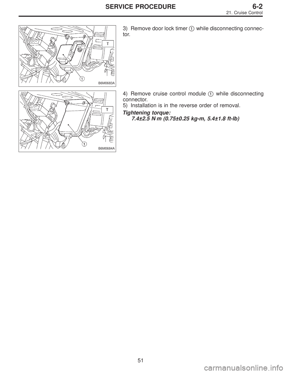
B6M0683A
3) Remove door lock timer�1while disconnecting connec-
tor.
B6M0684A
4) Remove cruise control module�1while disconnecting
connector.
5) Installation is in the reverse order of removal.
Tightening torque:
7.4±2.5 N⋅m (0.75±0.25 kg-m, 5.4±1.8 ft-lb)
51
6-2SERVICE PROCEDURE
21. Cruise Control
Page 1797 of 3342
 Turn ignition switch ON.
2) Check that indicator light comes on when")
C: DRIVING TESTS
Conduct road tests by selecting a smooth, flat road or use
free rollers as road test simulation.
1. MAIN SWITCH
1) Turn ignition switch ON.
2) Check that indicator light comes on when main switch
is pressed (ON).
3) Check that indicator light goes out when main switch is
pressed again (OFF).
4) Turn ignition switch OFF with main switch ON (which is
indicated by illumination.).
5) Turn ignition switch ON again to ensure that indicator
light remains OFF.
2. COMMAND SWITCH
1) Check that command switch is properly set in“SET/
COAST”,“RESUME/ACCEL”or“CANCEL”mode.
2) Also check that command switch returns to the original
position when released.
3. CONSTANT SPEED TEST
1) Turn main switch ON.
2) Drive vehicle at speed greater than 40 km/h (25 MPH).
3) Press command switch to set in“SET/COAST”mode.
4) Ensure that vehicle is maintained at the speed set when
command switch was pressed.
4. ACCELERATION TEST
1) Set vehicle speed at speed greater than 40 km/h (25
MPH).
2) Ensure that vehicle continues to accelerate while hold-
ing command switch in RESUME/ACCEL mode, and that
vehicle maintains that optional speed when command
switch is released.
5. DECELERATION TEST
1) Set vehicle speed at optional speed greater than 40
km/h (25 MPH).
2) Ensure that vehicle continues to decelerate while hold-
ing command switch in SET/COAST mode, and that it
maintains that optional speed when command switch is
released.
NOTE:
When vehicle speed reaches the lower speed limit of 30
km/h (19 MPH) during deceleration, cruise control will be
released.
52
6-2SERVICE PROCEDURE
21. Cruise Control
Page 1914 of 3342

LED No. Signal name Display
1 FWD switch FF
2 Kick-down switch KD
3——
4——
5 Brake switch BR
6 ABS switch AB
7 Cruise control set CR
8 Power switch PW
9——
10——
FF KD——BR
AB CR PW——
1
2345
678910
65. FUNCTION MODE: FA0
—ON↔OFF SIGNAL—
Requirement for LED“ON”.
LED No. 1 Fuse is installed in FWD switch.
LED No. 2 Kick-down switch is turned ON. (Europe and
General models only)
LED No. 5 Brake pedal is depressed.
LED No. 6 ABS signal is entered.
LED No. 7 Cruise control is set.
LED No. 8 Power switch is turned ON. (Europe and
General models only)
LED No. Signal name Display
1 N/P range switch NP
2 R range switch RR
3 D range switch RD
4 3 range switch R3
5 2 range switch R2
6 1 range switch R1
7 Diagnosis switch SS
8——
9——
10——
NP RR RD R3 R2
R1 SS———
1
2345
678910
66. FUNCTION MODE: FA1
—ON↔OFF SIGNAL—
Requirement for LED“ON”.
LED No. 1“N”or“P”range is selected.
LED No. 2“R”range is selected.
LED No. 3“D”range is selected.
LED No. 4“3”range is selected.
LED No. 5“2”range is selected.
LED No. 6“1”range is selected.
LED No. 7 Diagnosis connector is connected.
63
2-7ON-BOARD DIAGNOSTICS II SYSTEM
3. Diagnosis System
Page 1934 of 3342
Resistance to
body
(ohms)
Throttle position
sensorB54 8Throttle fully closed. 0.3—0.7
—
Throttle fully open. 4.3—4.9
Throttle posit")
ContentConnector
No.Terminal
No.Measuring conditionsVoltage
(V)Resistance to
body
(ohms)
Throttle position
sensorB54 8Throttle fully closed. 0.3—0.7
—
Throttle fully open. 4.3—4.9
Throttle position
sensor power
supplyB56 19Ignition switch ON (with engine
OFF)4.8—5.3—
ATF temperature
sensorB54 10ATF temperature 20°C(68°F) 2.9—4.0 2.1 k—2.9 k
ATF temperature 80°C (176°F) 1.0—1.4 275—375
Vehicle speed
sensor 1B54 12Vehicle stopped. 0
450—720
Vehicle speed at least 20 km/h (12
MPH)More than 1 (AC range)
Vehicle speed
sensor 2B56 11When vehicle is slowly moved at
least 2 meters (7ft).Less than 1)More than 9—
Engine speed
signalB54 5Ignition switch ON (with engine
OFF).More than 10.5
—
Ignition switch ON (with engine ON). 8—11
Cruise set signal B56 3When cruise control is set (SET
lamp ON).Less than 1
—
When cruise control is not set (SET
lamp OFF).More than 6.5
Torque control
signalB55 16 Ignition switch ON 4—6—
Mass air flow
signalB54 9 Engine idling after warm-up 0.5—1.2—
Shift solenoid 1 B55 141st or 4th gear More than 9
20—32
2nd or 3rd gear Less than 1
Shift solenoid 2 B55 131st or 2nd gear More than 9
20—32
3rd or 4th gear Less than 1
Shift solenoid 3 B55 15Selector lever in“N”range (with
throttle fully closed).Less than 1
20—32
Selector lever in“D”range (with
throttle fully closed).More than 9
Duty solenoid A B55 8Throttle fully closed (with engine
OFF) after warm-up.2.0—4.0
2.0—4.5
Throttle fully open (with engine
OFF) after warm-up.Less than 1
Dropping resistor B55 7Throttle fully closed (with engine
OFF) after warm-up.More than 8.5
12—18
Throttle fully open (with engine
OFF) after warm-up.Less than 1
Duty solenoid B B55 5When lock up occurs. More than 8.5
9—17
When lock up is released. Less than 0.5
Duty solenoid C
(AWD model only)B55 3Fuse on FWD switch More than 8.5
9—17 Fuse removed from FWD switch
(with throttle fully open and with
select lever in 1st gear).Less than 0.5
Sensor ground
line 1B54 7—0 Less than 1
Sensor ground
line 2B56 20—0 Less than 1
System ground
lineB56 1—0 Less than 1
Power system
ground lineB55 10—0 Less than 1
FWD switch
(AWD model only)B56 2Fuse removed. 6—9.1
—
Fuse installed. Less than 1
Data link signal
(Subaru select
monitor)B5612——
—
13——
AT diagnosis
signalB56 11 Ignition switch ON Less than 1)More than 4—
83
2-7ON-BOARD DIAGNOSTICS II SYSTEM
5. Specified Data
Page 1952 of 3342
B2M1279A
8B8
CHECK INHIBITOR SWITCH.
1) Turn ignition switch to OFF.
2) Place the selector lever in the“P”or“N”position.
3) Disconnect connector from transmission harness con-
nector.
4) Measure resistance between transmission harness
connector receptacle’s terminals.
: Connector & terminal
(T3) No. 11—No. 12:
Is the resistance less than 1Ω?
: Repair open circuit in harness between starter
motor and ignition switch connector.
: Replace inhibitor switch.
B2M0517A
8B9
CHECK STARTER INTERLOCK CIRCUIT.
1) Turn ignition switch to“ST”.
2) Measure voltage between clutch switch connector and
chassis ground.
: Connector & terminal
�With cruise control
(B107) No. 2 (+)—Chassis ground (�):
�Without cruise control
(B106) No. 2 (+)—Chassis ground (�):
Is the voltage more than 10 V?
: Replace starter interlock relay.
: Go to next step 3).
101
2-7ON-BOARD DIAGNOSTICS II SYSTEM
8. Diagnostics for Engine Starting Failure
Page 1953 of 3342
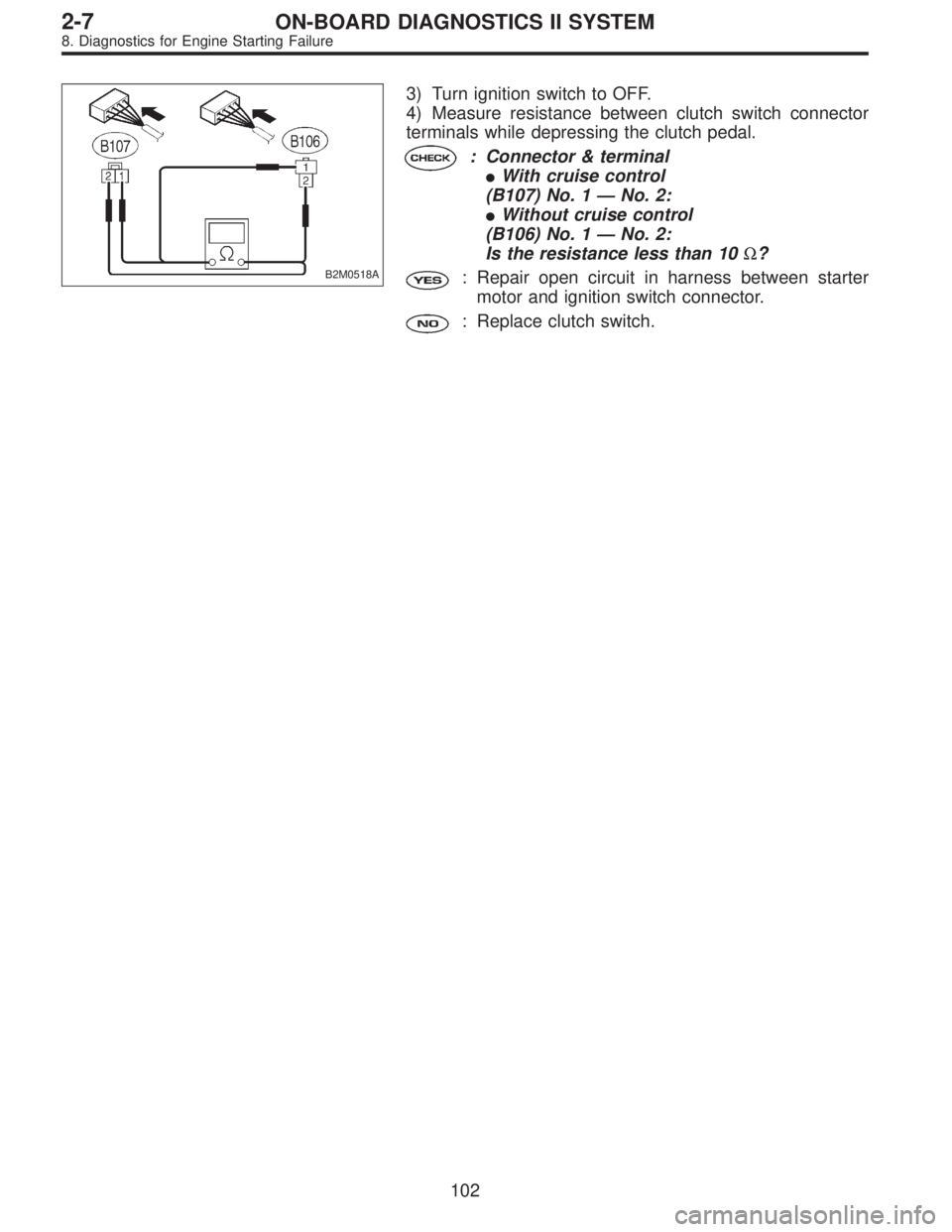
B2M0518A
3) Turn ignition switch to OFF.
4) Measure resistance between clutch switch connector
terminals while depressing the clutch pedal.
: Connector & terminal
�With cruise control
(B107) No. 1—No. 2:
�Without cruise control
(B106) No. 1—No. 2:
Is the resistance less than 10Ω?
: Repair open circuit in harness between starter
motor and ignition switch connector.
: Replace clutch switch.
102
2-7ON-BOARD DIAGNOSTICS II SYSTEM
8. Diagnostics for Engine Starting Failure
Page 1982 of 3342
![SUBARU LEGACY 1997 Service Repair Manual DTC
No.Abbreviation
(Subaru Select Monitor)Item Page
P1120 ST
—SWON Starter switch circuit high input 348
P1121 N
—SWON Neutral position switch circuit low input [AT vehicles] 350
P1122 BR
—HI P](/manual-img/17/57434/w960_57434-1981.png "SUBARU LEGACY 1997 Service Repair Manual DTC
No.Abbreviation
(Subaru Select Monitor)Item Page
P1120 ST
—SWON Starter switch circuit high input 348
P1121 N
—SWON Neutral position switch circuit low input [AT vehicles] 350
P1122 BR
—HI P")
DTC
No.Abbreviation
(Subaru Select Monitor)Item Page
P1120 ST
—SWON Starter switch circuit high input 348
P1121 N
—SWON Neutral position switch circuit low input [AT vehicles] 350
P1122 BR
—HI Pressure sources switching solenoid valve circuit high input 354
P1124 TCS
—HI TCS signal circuit high input 357
P1141 QA
—RHI Mass air flow sensor circuit range/performance problem (high input) 360
P1142 TH
—RLOW Throttle position sensor circuit range/performance problem (low input) 362
P1143 PS
—RLOW Pressure sensor circuit range/performance problem (low input) 364
P1144 PS
—RHI Pressure sensor circuit range/performance problem (high input) 368
P1400 PCVSOL
—LO Fuel tank pressure control solenoid valve circuit low input 370
P1420 PCVSOL
—HI Fuel tank pressure control solenoid valve circuit high input 374
P1421 EGRSOL
—HI Exhaust gas recirculation circuit high input 377
P1422 CPC
—HI Evaporative emission control system purge control valve circuit high input 380
P1423 VCMSOL
—HI Evaporative emission control system vent control high input 383
P1440 PCV
—FLOW Fuel tank pressure control system function problem (low input) 386
P1441 PCV
—FHI Fuel tank pressure control system function problem (high input) 390
P1442 FLVL
—R2 Fuel level sensor circuit range/performance problem 2 393
P1500 FAN
—1 Radiator fan relay 1 circuit low input 395
P1502 FAN
—F Radiator fan function problem 401
P1507 ISC
—SHI Idle control system malfunction (fail-safe) 403
P1520 FAN
—1HI Radiator fan relay 1 circuit high input 405
P1540 VSP
—S Vehicle speed sensor malfunction 2 407
P1700 ATTH Throttle position sensor circuit malfunction for automatic transmission 409
P1701 ATCRS Cruise control set signal circuit malfunction for automatic transmission 411
P1702 ATDIAG
—LO Automatic transmission diagnosis input signal circuit low input 413
P1722 ATDIAG
—HI Automatic transmission diagnosis input signal circuit high input 416
P1742 ATDIAG
—2 Automatic transmission diagnosis input signal circuit malfunction 419
131
2-7ON-BOARD DIAGNOSTICS II SYSTEM
10. Diagnostic Chart with Trouble Code for LHD Vehicles
 Remove nuts which secure actuator.
4) Remove actuator while disconnecting vacuum hose.
Tightening torque:
7.4±1.5 N⋅m (0.75±0.15 kg-m, 5.4±1.1 ft-lb)
B6M0359A
4. VACUUM PUMP AND VALVES")
 Turn ignition switch to OFF.
2) Place the selector lever in the“P”or“N”position.
3) Disconnect connector from transmission harness con-
nector.
4) Measu")