Page 480 of 3342
B2M1218
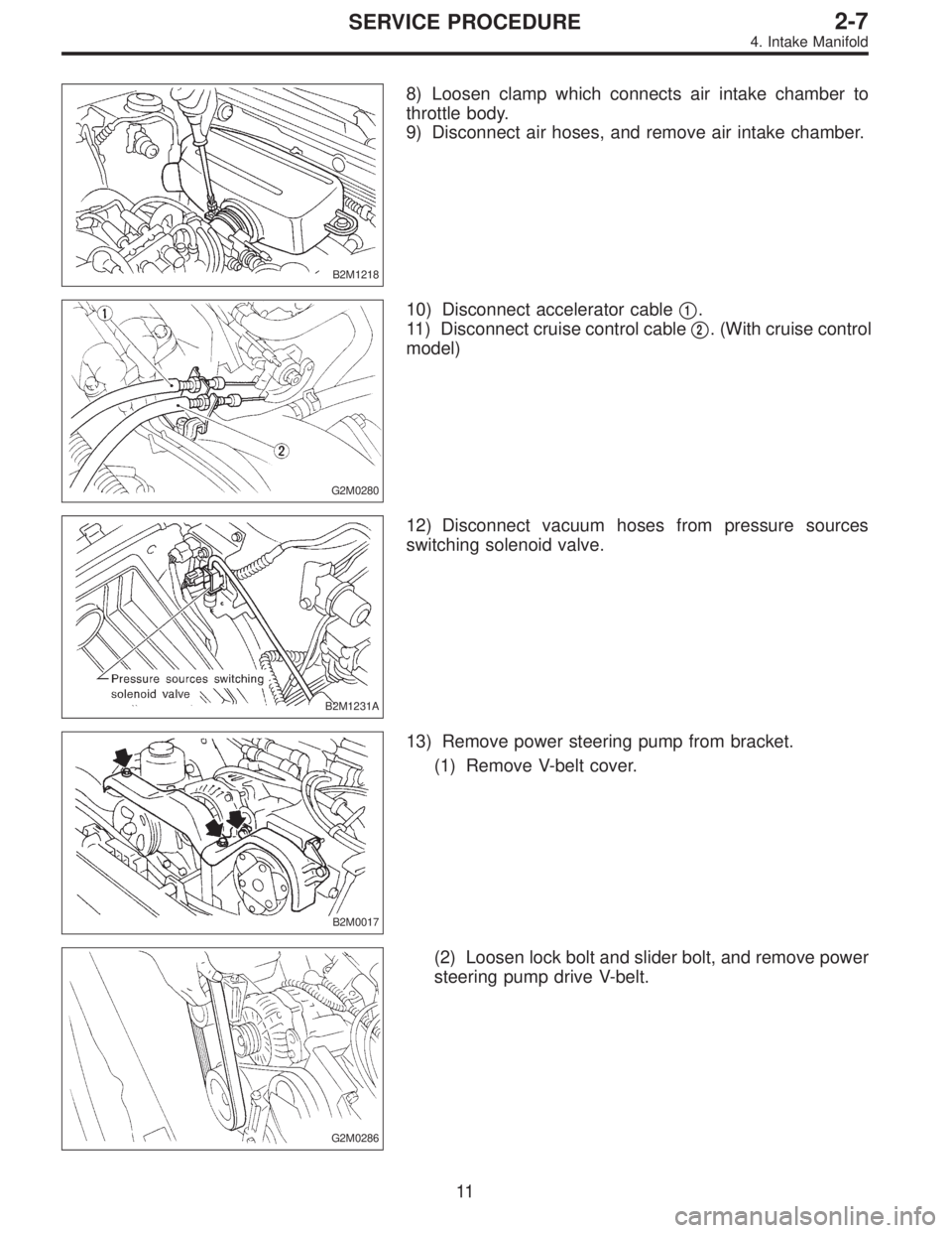
8) Loosen clamp which connects air intake chamber to
throttle body.
9) Disconnect air hoses, and remove air intake chamber.
G2M0280
10) Disconnect accelerator cable�1.
11) Disconnect cruise control cable�
2. (With cruise control
model)
B2M1231A
12) Disconnect vacuum hoses from pressure sources
switching solenoid valve.
B2M0017
13) Remove power steering pump from bracket.
(1) Remove V-belt cover.
G2M0286
(2) Loosen lock bolt and slider bolt, and remove power
steering pump drive V-belt.
11
2-7SERVICE PROCEDURE
4. Intake Manifold
Page 490 of 3342
B2M0340
(2) Install power steering pipe brackets on right side
intake manifold.
G2M0286
(3) Install power steering pump drive V-belt.
(4) Adjust V-belt.
B2M0017
(5) Install V-belt cover.
B2M1231A
18) Connect vacuum hoses to pressure sources switching
solenoid valve.
G2M0280
19) Connect accelerator cable�1.
20) Connect cruise control cable�
2. (With cruise control
model)
21
2-7SERVICE PROCEDURE
4. Intake Manifold
Page 602 of 3342
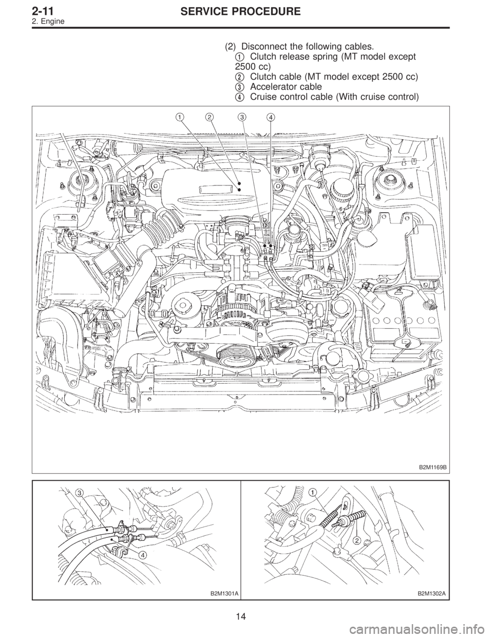
(2) Disconnect the following cables.
�
1Clutch release spring (MT model except
2500 cc)
�
2Clutch cable (MT model except 2500 cc)
�
3Accelerator cable
�
4Cruise control cable (With cruise control)
B2M1169B
B2M1301AB2M1302A
14
2-11SERVICE PROCEDURE
2. Engine
Page 612 of 3342
 Install front exhaust pipe and center exhaust pipe.
12) Connect hoses, connectors and cables.
(1) Connect the following hoses.
�Fuel delivery hose, return hose and evaporation
hose
�Heater inlet a")
11) Install front exhaust pipe and center exhaust pipe.
12) Connect hoses, connectors and cables.
(1) Connect the following hoses.
�Fuel delivery hose, return hose and evaporation
hose
�Heater inlet and outlet hoses
�Brake booster vacuum hose
(2) Connect the following connectors.
�Engine ground terminal
�Engine harness connectors
�Front oxygen sensor connector
�Rear oxygen sensor connector
�Alternator connector and terminal
�A/C compressor connectors (With A/C)
(3) Connect the following cables.
�Accelerator cable
�Cruise control cables (With cruise control)
�Clutch cable
�Clutch release spring
CAUTION:
After connecting each cable, adjust them.
B2M1168
13) Install air intake system.
(1) Install air cleaner element.
(2) Install air intake duct with air cleaner upper cover.
B2M0030
(3) Connect connector to mass air flow sensor.
G2M0270
14) Install A/C pressure hoses. (With A/C)
CAUTION:
Use new O-rings.
Tightening torque:
25±7 N⋅m (2.5±0.7 kg-m, 18.1±5.1 ft-lb)
24
2-11SERVICE PROCEDURE
2. Engine
Page 633 of 3342
20) Connect connectors and cables.
(1) Connect the following connectors.
�Transmission harness connectors
�Transmission ground terminal
�Front oxygen sensor connector
�Vehicle speed sensor 2
�Neutral position switch connector (MT model)
�Back-up light switch connector (MT model)
(2) Connect the following cables.
�Cruise control cable
(With cruise control model)
�Clutch cable
G2M0309
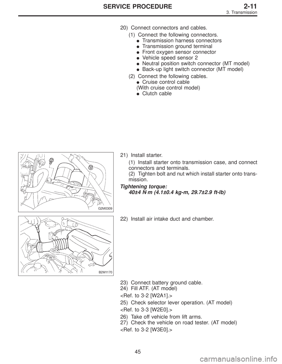
21) Install starter.
(1) Install starter onto transmission case, and connect
connectors and terminals.
(2) Tighten bolt and nut which install starter onto trans-
mission.
Tightening torque:
40±4 N⋅m (4.1±0.4 kg-m, 29.7±2.9 ft-lb)
B2M1170
22) Install air intake duct and chamber.
23) Connect battery ground cable.
24) Fill ATF. (AT model)
25) Check selector lever operation. (AT model)
26) Take off vehicle from lift arms.
27) Check the vehicle on road tester. (AT model)
45
2-11SERVICE PROCEDURE
3. Transmission
Page 1023 of 3342
G6M0095
17. Transmission Control Module
A: REMOVAL
1. LHD MODEL
1) Disconnect battery ground cable.
B3M0377A
2) Remove lower cover and then disconnect connector.
B3M0443A
3) Remove transmission control module.
�
1Transmission control module
�
2Cruise control module
�
3Pedal bracket
4) Disconnect connectors from transmission control mod-
ule.
G6M0095
2. RHD MODEL
1) Disconnect battery ground cable.
2) Remove lower cover and then disconnect connector.
B3M0445A
3) Remove transmission control module.
�
1Transmission control module
�
2Column shaft
4) Disconnect connectors from transmission control mod-
ule.
11 3
3-2SERVICE PROCEDURE
17. Transmission Control Module
Page 1024 of 3342
B3M0443A
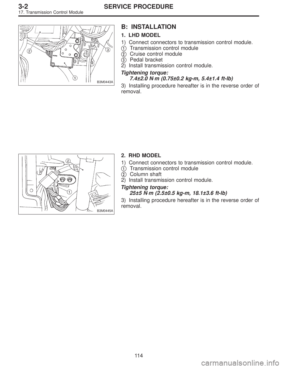
B: INSTALLATION
1. LHD MODEL
1) Connect connectors to transmission control module.
�
1Transmission control module
�
2Cruise control module
�
3Pedal bracket
2) Install transmission control module.
Tightening torque:
7.4±2.0 N⋅m (0.75±0.2 kg-m, 5.4±1.4 ft-lb)
3) Installing procedure hereafter is in the reverse order of
removal.
B3M0445A
2. RHD MODEL
1) Connect connectors to transmission control module.
�
1Transmission control module
�
2Column shaft
2) Install transmission control module.
Tightening torque:
25±5 N⋅m (2.5±0.5 kg-m, 18.1±3.6 ft-lb)
3) Installing procedure hereafter is in the reverse order of
removal.
11 4
3-2SERVICE PROCEDURE
17. Transmission Control Module
Page 1198 of 3342
G5M0328
6) Align center of roll connector. (with airbag model)
CAUTION:
Ensure that front wheels are set in straight-forward
direction.
7) Set steering wheel to neutral and install it onto steering
shaft.
Tightening torque:
34±5 N⋅m (3.5±0.5 kg-m, 25.3±3.6 ft-lb)
Column cover-to-steering wheel clearance:
2 — 4 mm (0.08 — 0.16 in)
CAUTION:
Insert roll connector guide pin into guide hole on lower
end of surface of steering wheel to prevent damage.
Draw out airbag system connector, horn connector
and cruise control connectors from guide hole of
steering wheel lower end. (with airbag model)
8) Install airbag module to steering wheel. (with airbag
model)
WARNING:
Always refer to 5-5 [W7B1] before performing the ser-
vice operation.
14
4-3SERVICE PROCEDURE
2. Tilt Steering Column
![SUBARU LEGACY 1997 Service Repair Manual B2M0340
(2) Install power steering pipe brackets on right side
intake manifold.
G2M0286
(3) Install power steering pump drive V-belt.
(4) Adjust V-belt. <Ref. to 1-5 [01A0].>
B2M0017
(5) Install V-bel](/manual-img/17/57434/w960_57434-489.png "SUBARU LEGACY 1997 Service Repair Manual B2M0340
(2) Install power steering pipe brackets on right side
intake manifold.
G2M0286
(3) Install power steering pump drive V-belt.
(4) Adjust V-belt. <Ref. to 1-5 [01A0].>
B2M0017
(5) Install V-bel")
 Disconnect battery ground cable.
B3M0377A
2) Remove lower cover and then disconnect connector.
B3M0443A
3) Remove transmission contro")
![SUBARU LEGACY 1997 Service Repair Manual G5M0328
6) Align center of roll connector. (with airbag model)
<Ref. to 5-5 [W7B1].>
CAUTION:
Ensure that front wheels are set in straight-forward
direction.
7) Set steering wheel to neutral and insta](/manual-img/17/57434/w960_57434-1197.png "SUBARU LEGACY 1997 Service Repair Manual G5M0328
6) Align center of roll connector. (with airbag model)
<Ref. to 5-5 [W7B1].>
CAUTION:
Ensure that front wheels are set in straight-forward
direction.
7) Set steering wheel to neutral and insta")